Qlogic SANbox2-64 User Manual
Switch management
Hide thumbs
Also See for SANbox2-64:
- Supplementary manual (2 pages) ,
- Brochure (2 pages) ,
- Supplementary manual (2 pages)
Table of Contents
Advertisement
Quick Links
Advertisement
Table of Contents

Related Manuals for Qlogic SANbox2-64


Summary of Contents for Qlogic SANbox2-64
- Page 1 S i m p l i f y SANbox2-64 Switch Management User’s Guide 59048-01 A Page i...
-
Page 2: Document Revision History
QLogic Corporation reserves the right to change product specifications at any time without notice. Applications described in this document for any of these products are for illustrative purposes only. QLogic Corporation makes no representation nor warranty that such applications are suitable for the specified use without further testing or modification. -
Page 3: Table Of Contents
Table of Contents Section 1 Introduction Intended Audience ..................... 1-1 Related Materials ....................1-1 Technical Support....................1-2 1.3.1 Availability....................1-2 1.3.2 Training...................... 1-2 1.3.3 Contact Information ................... 1-2 Section 2 Using SANbox Manager Installing SANbox Manager................2-1 2.1.1 SANsurfer Management Suite Disk - Windows Installation....... 2-2 2.1.2 SANsurfer Management Suite Disk - Linux Installation...... - Page 4 SANbox2-64 Switch Management User’s Guide 2.10.3 Topology Data Windows ................2-20 2.11 Using the Faceplate Display................2-21 2.11.1 I/O Blades....................2-21 2.11.2 Port Views and Status ................2-22 2.11.3 Working with I/O Blades and Ports ............2-22 2.11.3.1 Selecting I/O Blades and Ports............2-22 2.11.3.2...
- Page 5 SANbox2-64 Switch Management User’s Guide 3.4.5 Using the Edit Zoning Window ..............3-16 3.4.6 Managing Zone Sets ................3-18 3.4.6.1 Creating a Zone Set ............... 3-18 3.4.6.2 Activating and Deactivating a Zone Set.......... 3-19 3.4.6.3 Copying a Zone to a Zone Set............3-19 3.4.6.4...
- Page 6 SANbox2-64 Switch Management User’s Guide 4.7.1.2 Switch Administrative States............4-11 4.7.1.3 Domain ID and Domain ID Lock ............. 4-11 4.7.1.4 Broadcast Support ................4-12 4.7.1.5 Inband Management............... 4-12 4.7.1.6 Timeout Values ................4-13 4.7.2 Network Properties .................. 4-14 4.7.2.1 IP Configuration ................4-15 4.7.2.2...
- Page 7 SANbox2-64 Switch Management User’s Guide 6.2.4 Changing TL Modes ................6-11 6.2.5 Changing Buffer-to-Buffer Credits ............6-12 6.2.6 I/O Stream Guard ..................6-12 6.2.7 Extending Port Credits................6-12 6.2.8 Resetting a Port..................6-14 Testing Ports..................... 6-14 Appendix A Command Line Interface Logging On to a Switch ..................A-1...
- Page 8 SANbox2-64 Switch Management User’s Guide Zone Command..................A-75 Zoneset Command ..................A-79 Zoning Command ..................A-81 Appendix B Graphing Port Performance Starting SANsurfer Fabric View ................B-1 Displaying Graphs ....................B-2 B.2.1 Arranging Graphs in the Display..............B-2 B.2.2 Customizing Graphs ..................B-3 Appendix C Messages Fabrics File—Open, Save ..................C-1 Add a Fabric .......................C-2...
- Page 9 SANbox2-64 Switch Management User’s Guide 2-10 Topology Display......................2-17 2-11 Faceplate Display......................2-21 Add a New Fabric Window..................... 3-3 Active Zone Set Data Window ..................3-9 Zoning Config Window ....................3-13 Edit Zoning Window ..................... 3-16 Configured Zonesets Data Window ................4-6 Alarm Threshold Configuration Window.................
- Page 10 SANbox2-64 Switch Management User’s Guide Port Speeds ......................... 6-10 Port Modes........................6-11 Commands Listed by Authority Level................A-3 Switch Configuration Defaults ..................A-21 Port Configuration Defaults ..................A-21 Alarm Threshold Configuration Defaults ..............A-22 SNMP Configuration Defaults ..................A-23 System Configuration Defaults..................A-24 Set Config Port Parameters ..................A-27 Set Config Switch Parameters ..................A-29...
-
Page 11: Introduction
It is intended for users responsible for installing and using network management tools. Related Materials Refer to the following manuals for information about switch hardware and installation. SANbox2-64 Fibre Channel Switch Installation Guide, publication number 59043-01. 59048-01 A... -
Page 12: Technical Support
Contact Information for the latest firmware and software updates. 1.3.1 Availability QLogic Technical Support is available from 7:00 AM to 7:00 PM Central Standard Time, Monday through Friday, excluding QLogic-observed holidays. 1.3.2 Training QLogic offers the following technical training courses:... -
Page 13: Using Sanbox Manager
Section 2 Using SANbox Manager This section describes how to use the SANbox Manager application and its menus. The following topics are covered: Installing SANbox Manager Starting SANbox Manager Exiting SANbox Manager Changing the password for the default fabric view file Setting SANbox Manager user preferences Using online help SANbox Manager user interface... -
Page 14: Sansurfer Management Suite Disk - Windows Installation
2 – Using SANbox Manager Installing SANbox Manager Your switch was shipped with either a SANsurfer Management Suite Disk or a SANbox2 Installation Disk. Refer to the following installation instructions that correspond to your situation: SANsurfer Management Suite Disk - Windows Installation SANsurfer Management Suite Disk - Linux Installation SANsurfer Management Suite Disk - Solaris Installation SANbox2 Installation Disk - Windows Installation... -
Page 15: Sansurfer Management Suite Disk - Linux Installation
2 – Using SANbox Manager Installing SANbox Manager 2.1.2 SANsurfer Management Suite Disk - Linux Installation To install the SANbox Manager application on Linux from the SANsurfer Management Suite Disk, do the following: Close all programs currently running, and insert the SANsurfer Management Suite Disk into the management workstation CD-ROM drive. -
Page 16: Sansurfer Management Suite Disk - Solaris Installation
2 – Using SANbox Manager Installing SANbox Manager 2.1.3 SANsurfer Management Suite Disk - Solaris Installation To install the SANbox Manager application on Solaris from the SANsurfer Management Suite CD-ROM, do the following: Close all programs currently running, and insert the SANsurfer Management Suite Disk into the management workstation CD-ROM drive. -
Page 17: Sanbox2 Installation Disk - Windows Installation
2 – Using SANbox Manager Installing SANbox Manager 2.1.4 SANbox2 Installation Disk - Windows Installation To install the SANbox Manager application on Windows from the SANbox2 Installation Disk, do the following: Close all programs currently running, and insert the SANbox2 Installation Disk into the management workstation CD-ROM drive. -
Page 18: Starting Sanbox Manager
2 – Using SANbox Manager Starting SANbox Manager Starting SANbox Manager To start the SANbox Manager application for the first time, choose one of the following methods: For a Windows platform, double-click the SANbox Manager shortcut, or select SANbox Manager from Start menu, depending on how you installed the SANbox Manager application. -
Page 19: Add A New Fabric Window
2 – Using SANbox Manager Starting SANbox Manager Figure 2-2 Load Default Fabric View File Window To start using the SANbox Manager application, do the following to add a fabric: Open the Fabric menu and select Add Fabric to open the Add a New Fabric window as shown in Figure 2-3. -
Page 20: Exiting Sanbox Manager
2 – Using SANbox Manager Exiting SANbox Manager Exiting SANbox Manager When exiting SANbox Manager, the current fabric view is encrypted and saved to the default fabric view file (fc_view.dft). A password is required to encrypt and save the default fabric view file the first time you exit SANbox Manager. When you exit subsequent sessions, SANbox Manager closes and saves the default fabric view file automatically without having to enter a password. -
Page 21: Uninstalling Sanbox Manager
2 – Using SANbox Manager Uninstalling SANbox Manager Uninstalling SANbox Manager A program to uninstall SANbox Manager was installed as part of the SANbox Manager installation process. The Uninstaller Data folder in the Install folder contains the uninstall program (Uninstall SANbox Manager). Also, a shortcut/link to the uninstall program was installed in the installation directory during the SANbox Manager installation process. -
Page 22: Setting Preferences
2 – Using SANbox Manager Setting Preferences Setting Preferences Using the Preferences settings, you can: Change the location of the working directory in which to save files Change the location of the browser used to view the online help Choose the fabric discovery interval. The fabric discovery interval is how often the SANbox Manager application receives information from the fabric. -
Page 23: Using Online Help
2 – Using SANbox Manager Using Online Help Using Online Help Online help is available for the SANbox Manager application and its functions. The two ways to open the online help file are: open the Help menu and select Help Topics, or choose the Help button in the tool bar. Viewing Software Version and Copyright Information To view SANbox Manager software version and copyright information, open the Help menu and select About.. -
Page 24: Sanbox Manager User Interface
2 – Using SANbox Manager SANbox Manager User Interface SANbox Manager User Interface The SANbox Manager application uses two basic displays to manage the fabric and individual switches: the topology display and the faceplate display. The topology display shows all switches that are able to communicate and all connections between switches. -
Page 25: Menu Bar
2 – Using SANbox Manager SANbox Manager User Interface 2.9.1 Menu Bar The Menu Bar presents the SANbox Manager menus as shown in Figure 2-8. The menus and the tasks offered in them vary depending on the display. For example, the Port menu and many of the Switch menu selections, shown in gray, appear only in the faceplate display. -
Page 26: Tool Bar
2 – Using SANbox Manager SANbox Manager User Interface Some menu selections have shortcut keys as shown in Table 2-2. Table 2-2 Menu Shortcut Keys Shortcut Key Menu Selection F5 key View>Refresh Ctrl+O File>Open View File In addition to the menu bar, both the topology and faceplate displays have context sensitive menus that pop up when you click in the graphic window with the right mouse button. -
Page 27: Fabric Tree
Description Edit Zoning button - opens the Edit Zoning window (available only in faceplate display). The QLogic logo opens a link to the QLogic web site. 2.9.3 Fabric Tree The fabric tree lists the managed fabrics and their switches as shown in Figure 2- 9. -
Page 28: Graphic Window
2 – Using SANbox Manager SANbox Manager User Interface Each fabric tree entry has a small icon next to it that uses color to indicate operational status. A green icon indicates normal operation. A red icon indicates a communications failure. A blue icon indicates that a switch is unknown, or a switch with security enabled when the fabric management switch has security disabled. -
Page 29: Using The Topology Display
2 – Using SANbox Manager Using the Topology Display 2.10 Using the Topology Display The topology display shown in Figure 2-10 receives information from the selected fabric and displays its topology. Switches and inter-switch links (ISL) appear in the graphic window and use color to indicate status. Consider the following topology display features: Switch and link status Working with switches and links... -
Page 30: Working With Switches And Links
2 – Using SANbox Manager Using the Topology Display 2.10.2 Working with Switches and Links Switch and link icons are selectable and moveable, and serve as access points for other displays and menus. You select switches and links to display information about them, modify their configuration, or delete them from the display. -
Page 31: Opening The Faceplate Display And Popup Menus
2 – Using SANbox Manager Using the Topology Display 2.10.2.3 Opening the Faceplate Display and Popup Menus The faceplate display shows the front of a single switch and its ports. To open the faceplate display when viewing the topology display, click the switch entry/icon in the fabric tree, or double-click the switch graphic. -
Page 32: Topology Data Windows
2 – Using SANbox Manager Using the Topology Display 2.10.3 Topology Data Windows The topology display provides the following data windows corresponding to the data window tabs: Name Server – displays all devices logged with the name server and their addresses within the current fabric configuration. -
Page 33: Using The Faceplate Display
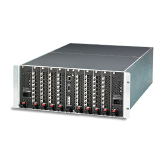
I/O blades. I/O blade failure status is indicated by a status icon as shown Figure 2-11. The SANbox2-64 switch numbers its slots from 0–10 from left to right. I/O blades occupy slots 1–4 and 6–9. Ports on an I/O blade are numbered from 0–7 from top to bottom in slot 1, 8–15 in slot 2, and so on to 56–63 in slot 9. -
Page 34: Port Views And Status
2 – Using SANbox Manager Using the Faceplate Display 2.11.2 Port Views and Status Port color and text provides information about the port and its operational state. Green indicates active; gray indicates inactive. The faceplate display provides the following views of port status corresponding to the View menu options in the faceplate display. -
Page 35: Opening Popup Menus
2 – Using SANbox Manager Using the Faceplate Display 2.11.3.2 Opening Popup Menus Using the right mouse button, you can open the faceplate popup menu. This popup menu presents several selections to manage the switch, I/O blades, and ports. To open the popup menu, right-click anywhere in the graphic window. If no I/O blades or ports are selected, the corresponding tasks will be unavailable in the menu. - Page 36 2 – Using SANbox Manager Using the Faceplate Display Notes 2-24 59048-01 A...
- Page 37 Section 3 Managing Fabrics This section describes the following tasks that manage fabrics: Security Managing the fabric database Displaying fabric information Zoning a fabric Security The components of security are: User authentication Inter-Switch link security Inband management 3.1.1 User Authentication User Authentication security pertains to gaining access to a switch after entering a valid account name/password combination entered by the user.
-
Page 38: Managing Fabrics Security
3 – Managing Fabrics Security Once access is gained to the entry switch in a fabric, that user may access all switches in that fabric (if ISL Security is not disabled). Refer to ”Inter-Switch Link Security” on page 3-2 for more information. 3.1.2 Inter-Switch Link Security Inter-Switch Link security pertains to whether the switches in the fabric are... -
Page 39: Managing The Fabric Database
3 – Managing Fabrics Managing the Fabric Database Managing the Fabric Database A fabric database contains the set of fabrics that you have added during a SANbox Manager session. Initially, the SANbox Manager application opens with an empty fabric database. 3.2.1 Adding a Fabric To add a fabric to the database, do the following:... -
Page 40: Removing A Fabric
3 – Managing Fabrics Managing the Fabric Database 3.2.2 Removing a Fabric To delete a fabric file from the database, do the following: Select a fabric in the fabric tree. Open the Fabric menu and select Remove Fabric. 3.2.3 Opening a Fabric View File To open an existing view file, do the following: Open the File menu, and select Open View File, or choose the Open button. -
Page 41: Adding A New Switch To A Fabric
3 – Managing Fabrics Managing the Fabric Database 3.2.6 Adding a New Switch to a Fabric If there are no special conditions to be configured for the new switch, simply plug in the switch and the switch becomes functional with the default fabric configuration. -
Page 42: Replacing A Failed Switch
3 – Managing Fabrics Managing the Fabric Database 3.2.7 Replacing a Failed Switch The archive/restore works for all switches. However, the Restore menu item is not available for the inband switches. You can only restore a switch out-of-band (the connection switch). Use the following procedure to replace a failed switch for which an archive is available. -
Page 43: Deleting Switches And Links
3 – Managing Fabrics Displaying Fabric Information 3.2.8 Deleting Switches and Links The SANbox Manager application does not automatically delete switches or links that have failed or have been physically removed from the Fibre Channel network. In these cases, you can delete switches and links to bring the display up to date. If you delete a switch or a link that is still active, the SANbox Manager application will restore it automatically. -
Page 44: Active Zone Set Data Window
Table 3-1 shows the different switch icons and their meanings. Table 3-1 Topology Display Switch and Status Icons Switch Icon Description SANbox2-64 switch Normal operation (Green) Warning–operational with errors (Yellow) Critical–communication interrupted (Red) Unknown–communication status unknown (Blue) Fabric Management Switch... -
Page 45: Zoning A Fabric
3 – Managing Fabrics Zoning a Fabric The Active Zoneset data window, shown in Figure 3-2, uses display conventions for expanding and contracting entries that are similar to the fabric tree. An entry handle located to the left of an entry in the tree indicates that the entry can be expanded. -
Page 46: Zoning Concepts
3 – Managing Fabrics Zoning a Fabric 3.4.1 Zoning Concepts The following zoning concepts provide some context for the zoning tasks described in this section: Zones Aliases Zone sets Zoning database Zoning configuration 3.4.1.1 Zones A zone is a named group of ports or devices that can communicate with each other. -
Page 47: Access Control List Hard Zones
3 – Managing Fabrics Zoning a Fabric 3.4.1.1.2 Access Control List Hard Zones Access Control List (ACL) zoning divides the fabric for purposes of controlling discovery and inbound traffic. ACL zoning is a type of hard zoning that is hardware enforced. This type of zoning is useful for controlling access to certain devices without totally isolating them from the fabric. -
Page 48: Aliases
3 – Managing Fabrics Zoning a Fabric 3.4.1.2 Aliases To make it easier to add a group of ports or devices to one or more zones, you can create an alias. An alias is a named set of ports or devices that are grouped together for convenience. -
Page 49: Zoning Configuration
3 – Managing Fabrics Zoning a Fabric 3.4.1.5 Zoning Configuration You can set the Auto Save and Default Visibility zoning configuration parameters using SANbox Manager or the Set Config Zoning command. The Auto Save parameter determines whether changes to the active zone set that a switch receives from other switches in the fabric will be saved to permanent memory on that switch. -
Page 50: Default Visibility
3 – Managing Fabrics Zoning a Fabric 3.4.2.2 Default Visibility Default visibility determines the level of communication that is permitted among ports/devices when there is no active zone set. The default visibility parameter can be set differently on each switch. When default visibility is enabled (ALL) on a switch, all ports/devices on the switch can communicate with all ports/devices on switches that also have default visibility enabled. -
Page 51: Zone Merge Failure
3 – Managing Fabrics Zoning a Fabric 3.4.4.1 Zone Merge Failure If a zone merge is unsuccessful, the inter-switch links between the fabrics will isolate due to a zone merge failure, which will generate an alarm log entry. The reason for the E_Port isolation can also be determined by viewing the port information. -
Page 52: Using The Edit Zoning Window
3 – Managing Fabrics Zoning a Fabric 3.4.5 Using the Edit Zoning Window To edit the zoning database for a particular switch, open the Zoning menu from the faceplate display and select Edit Zoning to open the Edit Zoning window shown in Figure 3-4. -
Page 53: Edit Zoning Window
3 – Managing Fabrics Zoning a Fabric Using tool bar buttons, popup menus, or a drag-and-drop method, you can create and manage zone sets and zones in the zoning database. The Apply button saves changes to the zoning database without closing the window. The OK button saves the zoning changes to the database and closes the window. -
Page 54: Managing Zone Sets
3 – Managing Fabrics Zoning a Fabric 3.4.6 Managing Zone Sets Zoning a fabric involves creating a zone set, creating zones as zone set members, then adding devices as zone members. The zoning database supports multiple zone sets to serve the different security and access needs of your storage area network, but only one zone set can be active at one time. -
Page 55: Activating And Deactivating A Zone Set
3 – Managing Fabrics Zoning a Fabric 3.4.6.2 Activating and Deactivating a Zone Set You must activate a zone set to apply its zoning definitions to the fabric. Only one zone set can be active at one time. When you activate a zone set, the switch distributes that zone set to the temporary zoning database on every switch in the fabric. -
Page 56: Removing A Zone Set
3 – Managing Fabrics Zoning a Fabric 3.4.6.5 Removing a Zone Set Removing a zone set from the database affects the member zones in the following ways. Member zones that are members of other zone sets are not affected. Member zones that are not members of other zone sets become members of the orphan zone set. -
Page 57: Managing Zones
3 – Managing Fabrics Zoning a Fabric 3.4.7 Managing Zones Managing zones involves the following: Creating a zone in a zone set Adding zone members Renaming a zone or a zone set Removing a zone member Removing a zone from a zone set Removing a zone from all zone sets Changing zone types Note:... -
Page 58: Adding Zone Members
3 – Managing Fabrics Zoning a Fabric To add ports or devices to the zone, do one of the following: In the zone set tree, select the zone set. In the graphic window, select the port to add to the zone. Open the Edit menu and select Add Members. -
Page 59: Removing A Zone Member
3 – Managing Fabrics Zoning a Fabric 3.4.7.4 Removing a Zone Member Removing a zone member will affect every zone and zone set in which that zone is a member. To remove a member from a zone: In the Edit Zoning window, select the zone member to be removed. Open the Edit menu and select Remove. -
Page 60: Changing Zone Types
ACL zones need not include inter-switch links. VPF zoning is hard zoning that defines ports that can communicate with each other. VPF zones must include inter-switch links. On a SANbox2-64 switch, a VPF zone cannot extend beyond the ports of a single I/O blade. 3.4.8 Managing Aliases An alias is a collection of objects that can be zoned together. -
Page 61: Adding A Member To An Alias
3 – Managing Fabrics Zoning a Fabric 3.4.8.2 Adding a Member to an Alias The three ways to add a member to an alias are: Drag-and-drop method. Select the alias in the left pane and the member in the right pane to add to that alias, and choose the Insert button. - Page 62 3 – Managing Fabrics Zoning a Fabric Notes 3-26 59048-01 A...
-
Page 63: Managing Switches
Section 4 Managing Switches This section describes the following tasks that manage switches in the fabric. Displaying switch information Managing alarms Exporting name server information to a file Paging a switch Resetting a switch Setting the date and time Configuring a switch Archiving a switch Restoring a switch Managing firmware... -
Page 64: Name Server Data Window
4 – Managing Switches Displaying Switch Information Right-click a switch in the topology display and select Refresh Switch from the popup menu. Right-click in the graphic window of the faceplate display, and select Refresh Switch from the popup menu. 4.1.1 Name Server Data Window The Name Server data window displays information about the devices that are logged into the fabric. - Page 65 4 – Managing Switches Displaying Switch Information Table 4-2 Switch Data Window Entries Entry Description FcAddress Switch Fibre Channel address World Wide Name Switch worldwide name Reason for Status Additional status information User Name Account name Login Level Authority level Vendor Switch manufacturer Flash Version...
-
Page 66: Link Data Window
4 – Managing Switches Displaying Switch Information Table 4-2 Switch Data Window Entries (Continued) Entry Description Zoning Merge Auto Save Zoning auto save status. Saves zoning updates in temporary and permanent memory (True) or only in temporary memory (False). Zoning Default Visibility Zoning visibility status. -
Page 67: Port Statistics Data Window
4 – Managing Switches Displaying Switch Information 4.1.4 Port Statistics Data Window The Port Statistics data window displays port performance data for the selected ports. To open the Port Statistics data window, choose the Port Stats tab below the data window in the faceplate display. Refer to Table 6-5 for a description of the Port Statistics data window entries. -
Page 68: Alarm Log Data Window
4 – Managing Switches Managing Alarms Figure 4-1 Configured Zonesets Data Window 4.1.7 Alarm Log Data Window The Alarm Log data window displays switch event information. To open the Alarm Log data window, choose the Alarm Log tab below the data window in the faceplate display. -
Page 69: Configuring Alarms
4 – Managing Switches Managing Alarms 4.2.1 Configuring Alarms Configuring an alarm involves choosing an event type, rising and falling thresholds, a sampling interval, and finally enabling or disabling the alarm. To configure alarms, do the following: In the faceplate display, open the Switch menu and select Configure Alarm Thresholds. -
Page 70: Exporting Alarm Log Information To A File
4 – Managing Switches Managing Alarms Enter values for the rising and falling thresholds. The rising threshold is the count above which an alarm is generated. When the count exceeds the rising threshold, one alarm is generated. The switch will not generate another alarm for that event until the count descends below the falling threshold, resetting the eligibility, and again exceeds the rising threshold. -
Page 71: Exporting Name Server Information To A File
4 – Managing Switches Exporting Name Server Information to a File Exporting Name Server Information to a File To save name server information to a file, open the topology display and do the following: Select one or more switches. If no switches are selected, name server information is gathered for the all switches. -
Page 72: Configuring A Switch
4 – Managing Switches Configuring a Switch Configuring a Switch Switch configuration is divided into two areas: chassis configuration and network configuration. Chassis configuration specifies switch-wide Fibre Channel settings. Network configuration specifies Ethernet and SNMP settings. To open the Switch Properties window, open the Switch menu and select Switch Properties. -
Page 73: Switch Administrative States
4 – Managing Switches Configuring a Switch 4.7.1.2 Switch Administrative States The switch administrative state determines the operational state of the switch and its ports. The switch administrative state exists in two forms: the configured administrative state and the current administrative state. The configured administrative state is the state that is saved in the switch configuration and is preserved across switch resets. -
Page 74: Broadcast Support
4 – Managing Switches Configuring a Switch If you connect a new switch to an existing fabric with its domain ID unlocked, and a domain conflict occurs, the new switch will isolate as a separate fabric. However, you can remedy this by resetting the new switch or taking it offline then back online. -
Page 75: Timeout Values
4 – Managing Switches Configuring a Switch 4.7.1.6 Timeout Values The switch timeout values determine the timeout values for all ports on the switch. Table 4-4 describes the switch timeout parameters. The R_A_TOV, R_T_TOV, or E_D_TOV values must be the same for all switches in the fabric. Note: Timeout values can only be changed if the switch is offline. -
Page 76: Network Properties
4 – Managing Switches Configuring a Switch 4.7.2 Network Properties Use the Network Properties window shown in Figure 4-5 to change IP and SNMP configuration parameters. After making changes, choose the OK button to put the new values into effect. To open the Network Properties window, open the Switch menu and select Network Properties. -
Page 77: Ip Configuration
4 – Managing Switches Configuring a Switch 4.7.2.1 IP Configuration The IP configuration identifies the switch on the Ethernet network and determines which boot method to use. Table 4-5 describes the IP configuration parameters. Table 4-5 IP Configuration Parameters Parameter Description IP Address Internet Protocol (IP) address for the Ethernet port. -
Page 78: Remote Logging
4 – Managing Switches Configuring a Switch 4.7.2.2 Remote Logging The Remote Logging (syslog) feature enables saving of the log information to a remote host that supports the syslog protocol. When enabled, the log entries are sent to the syslog host at the IP address that you specify in the Logging Host IP Address field. -
Page 79: Snmp Trap Configuration
4 – Managing Switches Configuring a Switch 4.7.2.4 SNMP Trap Configuration The SNMP trap configuration defines how traps are set. Table 4-7 describes the SNMP configuration parameters. Table 4-7 SNMP Trap Configuration Parameters Parameter Description Trap Enabled Check box to enable or disable the trap. Trap Address Specifies the IP address to which SNMP traps are sent. -
Page 80: Archiving A Switch
The switch configuration must be archived before it can be restored. Furthermore, the switch archive must be compatible with the switch to be restored; that is, you cannot restore a SANbox2-64 switch with a SANbox2-16 archive. Refer to ”Archiving a Switch” on page 4-18 for more information. -
Page 81: Managing Firmware
4 – Managing Switches Managing Firmware 4.10 Managing Firmware The switch memory is partitioned for two firmware images. This can be useful when upgrading so that both the old an new firmware can be maintained on the switch. When you install new firmware, the currently active firmware is preserved and the new firmware becomes the second image or the fallback version. -
Page 82: Restoring The Factory Default Configuration
Restoring the switch to the factory default configuration does not restore the account name and password settings. To restore user accounts, you must select Reset Password File in the maintenance menu. Refer to “Recovering a Switch” in the SANbox2-64 Fibre Channel Switch Installation Guide. Table 4-8 Factory Default Configuration Settings Setting... - Page 83 4 – Managing Switches Restoring the Factory Default Configuration Table 4-8 Factory Default Configuration Settings (Continued) Setting Value Write community Private Port state Online Port speed Auto-detect Port mode 59048-01 A 4-21...
- Page 84 4 – Managing Switches Restoring the Factory Default Configuration Notes 4-22 59048-01 A...
-
Page 85: Managing I/O Blades
Section 5 Managing I/O Blades An I/O blade is a component switch of the larger SANbox2-64 switch. When you configure an I/O blade and its ports you are really configuring the slot. Because this configuration is saved on the switch CPU, any I/O blade that you install in that slot will acquire that configuration. -
Page 86: Changing The I/O Blade Administrative State
5 – Managing I/O Blades Changing the I/O Blade Administrative State Changing the I/O Blade Administrative State The I/O blade administrative state determines the operational status of the I/O blade and its ports. The I/O blade administrative state exists in two forms: the configured administrative state and the current administrative state. -
Page 87: Resetting An I/O Blade
5 – Managing I/O Blades Resetting an I/O Blade Resetting an I/O Blade Resetting an I/O blade reinitializes the I/O blade and its ports. This places the I/O blade and all of its ports online. To reset an I/O blade, do the following: Select one or more blades in the faceplate display. - Page 88 5 – Managing I/O Blades Hot Swap Wizard Removing an I/O Blade Select the Remove a Blade hot swap procedure Select and confirm the slot from which to remove the blade. The Port Status LEDs will flash green to positively identify the I/O blade.
-
Page 89: Managing Ports
Section 6 Managing Ports This section describes the following tasks that manage ports and devices: Displaying port information Configuring ports Testing ports Displaying Port Information Port information is available primarily in the faceplate display shown in Figure 6-1. The faceplate display data windows provide information and statistics for switches and ports. -
Page 90: Monitoring Port Status
6 – Managing Ports Displaying Port Information 6.1.1 Monitoring Port Status The faceplate display provides the following port related information: Port mode Port operational state Port speed Port media To display port number and status information for a port, position the cursor over a port on the faceplate display. -
Page 91: Displaying Port Operational States
6 – Managing Ports Displaying Port Information 6.1.1.2 Displaying Port Operational States To display the operational state on each port in the faceplate display, open the View menu and select View Port States. Table 6-2 lists the possible operational states and their meanings. The port operational state refers to actual port state and not the administrative state you may have assigned. -
Page 92: Displaying Tranceiver Media Status
6 – Managing Ports Displaying Port Information 6.1.1.4 Displaying Tranceiver Media Status To display transceiver media status, open the View menu and select View Port Media. Table 6-2 lists the possible media states and their meanings. Table 6-4 Transceiver Media View Media Icon Description Optical SFP, Online (Green) - Page 93 6 – Managing Ports Displaying Port Information Table 6-5 Port Statistics Data Window Entries (Continued) Entry Description Logout Count Number of logouts that have occurred on the switch. Al Init Count Number of times the port entered the initialization state. Invalid Destination Number of address identifiers (S_ID, D_ID) found to be in Address...
- Page 94 6 – Managing Ports Displaying Port Information Table 6-5 Port Statistics Data Window Entries (Continued) Entry Description Class 3 Toss Count Number of class 2 and class 3 sequences that were discarded by this port. A sequence can be discarded because of detection of a missing frame (based on SEQ_CNT), detection of an E_D_TOV timeout, receiving a reject frame, receiving frames for a stopped sequence, or other causes.
-
Page 95: Port Information Data Window
6 – Managing Ports Displaying Port Information 6.1.3 Port Information Data Window The Port Information data window displays port detail information for the selected port. To open the Port Information data window, choose the Port Info tab below the data window in the faceplate display. Information Table 6-6 Port Data Window Entries... -
Page 96: Name Server Data Window
6 – Managing Ports Configuring Ports 6.1.4 Name Server Data Window The Name Server data window displays information about the port and the connected device. To open the Name Server data window, select one or more switches in the topology display and choose the Name Server tab below the data window. -
Page 97: Changing Port Administrative States
6 – Managing Ports Configuring Ports The Port Properties window displays the switch name and the selected port(s). Use the Port Properties window to change the following parameters: Port state Port speed Port mode TL mode Port buffer credits I/O Stream Guard (RSCN Suppression) 6.2.1 Changing Port Administrative States The port administrative state determines the operational state of a port. -
Page 98: Changing Port Speeds
6 – Managing Ports Configuring Ports 6.2.2 Changing Port Speeds The SANbox2 switch ports are capable of transmitting and receiving at 1 or 2 Gbps. The ports can be configured for either transmission speed or to sense the transmission speed of the device to which it is connected. Table 6-8 describes the port speeds. -
Page 99: Changing Tl Modes
Translated loop port - Supports a loop of up to 124 private target or 125 private initiator devices capable of communicating with up to 63 off-loop initiator devices or 64 off-loop target devices. Refer to the SANbox2-64 Fibre Channel Switch Installation Guide for more information about TL_Ports. -
Page 100: Changing Buffer-To-Buffer Credits
Each port has a receive buffer capacity of 12 Fibre Channel frames or credits which is equal to approximately 24K bytes. Port buffer credits can be changed on ports to allow connections to non-QLogic switches that have different port buffer capacities. To change port buffer credits, do the following: Select one or more ports in the faceplate display. -
Page 101: Extended Credits Window
6 – Managing Ports Configuring Ports In the faceplate display, select the recipient ports. Recipient ports must be configured as G_Ports or F_Ports. Open the Port menu and select Extended Credits. This opens the Extended Credits window shown in Figure 6-3. -
Page 102: Resetting A Port
6 – Managing Ports Testing Ports 6.2.8 Resetting a Port The Reset Port option reinitializes the port using configuration parameters in memory. To reset a port, do the following: In the Faceplate Display, select the port(s) to be reset. Open the Port menu and select Reset Port. Testing Ports The port loopback tests verify correct port operation by sending a frame out through the loop, and then verifying that the frame received matches the frame... - Page 103 6 – Managing Ports Testing Ports SFP level (External) - The SFP level test also verifies port circuitry. The SFP level test sends a test frame from the ASIC through the SerDes chip, through the SFP transceiver fitted with a loopback plug, and back to the ASIC for the selected ports.
- Page 104 6 – Managing Ports Testing Ports Notes 6-16 59048-01 A...
-
Page 105: Appendix A Command Line Interface
Appendix A Command Line Interface Each switch contains a Telnet server. This server allows a Telnet client to establish a Telnet session with the switch to retrieve information or to configure parameters using the Command Line Interface (CLI). The CLI enables you to perform a variety of fabric and switch management tasks through an Ethernet or a serial port connection. -
Page 106: Command Syntax
A – Command Line Interface Command Syntax Command Syntax The command syntax is as follows: command keyword keyword [value] keyword [value1] [value2] The Command is followed by one or more keywords. Consider the following rules and conventions: Commands and keywords are lowercase and case sensitive. Commands with keywords require one of those keywords. -
Page 107: Commands
A – Command Line Interface Commands Commands The command set provides for User and Admin authority levels. User authority grants viewing access to the fabric and switches using the Show command and other read-only commands. Admin authority includes the User authority and grants permission to use the Admin command. -
Page 108: Admin Command
Admin Cancel command. Examples The following example shows how to open and close an Admin session: SANbox2-64 N108 #> admin start SANbox2-64 N108 (admin) #> SANbox2-64 N108 (admin) #> admin end 59048-01 A... -
Page 109: Alias Command
A – Command Line Interface Alias Command Alias Command Creates a named set of ports/devices. Aliases make it easier to assign a set of ports/devices to many zones. An alias can not have a zone or another alias as a member. - Page 110 A – Command Line Interface Alias Command members [alias] Displays all members of the alias given by [alias]. This keyword is available with User authority and does not require a zoning edit session or an admin session. remove [alias] [members] Removes the ports/devices given by [members] from the alias given by [alias].
-
Page 111: Config Command
A – Command Line Interface Config Command Config Command Manages the Fibre Channel configurations on a switch. For information about setting the port and switch configurations, refer to the ”Set Config Command” on page A-27. Authority Admin for all keywords except List Syntax config activate [config]... - Page 112 The following shows an example of how to open and close a Config Edit session: SANbox2-64 N108 #> admin start SANbox2-64 N108 (admin) #> config edit SANbox2-64 N108 (admin-config) #>> config cancel Configuration mode will be canceled.Please confirm (y/n): [n] y SANbox2-64 N108 (admin) #>...
-
Page 113: Date Command
Specifies the date – this requires an admin session. If you omit [MMDDhhmmCCYY], the current date is displayed – this is available with User authority. Examples The following is an example of the Date command: SANbox2-64 N108 #> date Tue Nov 12 07:51:24 2002 59048-01 A... -
Page 114: Fallback Command
After executing the Fallback command, reset the switch for the firmware to be placed in effect. Examples The following is an example of the Fallback command: SANbox2-64 N108 #> admin start SANbox2-64 N108 (admin) #> fallback Reverting to previous software image. Please confirm (y/n): [n] y SANbox2-64 N108 #>... -
Page 115: Help Command
The following is an example of the Help Set Beacon command: SANbox2-64 N108 #> help set beacon set beacon On | Off This command allows the LEDs on the front of the switch to flash. -
Page 116: History Command
Enter ![partial command string] to re-execute a command that matches the command string. Enter !! to re-execute the most recent command. Examples The following is an example of the History command: SANbox2-64 N108 #> history 1 show switch 2 date 3 help set 4 history SANbox2-64 N108 #>... -
Page 117: Hotswap Command
Examples The following is an example of the Hotswap Replace command: SANbox2-64> hotswap This command will guide you through the hotswap process. If this process is not followed exactly, then a seamless transition cannot be guaranteed and a switch power cycle will be required. - Page 118 A – Command Line Interface Hotswap Command Attach all connections, if any, to the IO blade in slot 6. Please confirm that these steps have been accomplished by pressing the ENTER key. Hotswap IO blade process successfully completed. Diagnostics has been run on the IO blade in slot 6: Passed A-14 59048-01 A...
-
Page 119: Image Command
A – Command Line Interface Image Command Image Command Manages and installs switch firmware. Authority Admin Syntax image cleanup fetch [account_name] [ip_address] [file_source] [file_destination] list unpack [file] Keywords cleanup Removes all firmware image files from the switch. All firmware image files are removed automatically each time the switch is reset. -
Page 120: Lip Command
Lip Command Reinitializes the specified loop port. Authority Admin Syntax lip [port_number] Keywords [port_number] The number of the port to be reinitialized. Examples The following is an example of the Lip command: SANbox2-64 N108 (admin) #> lip 2 A-16 59048-01 A... -
Page 121: Passwd Command
Examples The following is an example of the Passwd command: SANbox2-64 N108 (admin) #> passwd user2 Press ’q’ and the ENTER key to abort this command. account OLD password... -
Page 122: Ps Command
Ps Command Ps Command Displays current system process information. Authority User Syntax Examples The following is an example of the Ps command: SANbox2-64 N108 #> ps PPID %CPU TIME ELAPSED COMMAND 0.0 00:00:00 4-01:33:01 cns 0.0 00:00:00 4-01:33:01 ens 0.0 00:00:00 4-01:33:01 dlog 0.0 00:00:41... -
Page 123: Quit Command
A – Command Line Interface Quit Command Quit Command Closes the Telnet session. Authority User Syntax quit, exit, or logout 59048-01 A A-19... -
Page 124: Reset Command
A – Command Line Interface Reset Command Reset Command Resets the switch and port configuration parameters. Authority Admin Syntax reset blade [slot_number] config [config_name] factory port [port_number] snmp switch (default) system zoning Keywords blade [slot_number] Resets the I/O or cross-connect blade that occupies the slot given by [slot_number]. -
Page 125: A-2 Switch Configuration Defaults
A – Command Line Interface Reset Command zoning Clears the zoning database and deactivates the active zone set. The zoning configuration values (autosave, default visibility) remain unchanged. Notes The following tables specify the various factory default settings: Table A-2. Switch Configuration Defaults Parameter Default Admin State... -
Page 126: A-4 Alarm Threshold Configuration Defaults
A – Command Line Interface Reset Command Table A-3. Port Configuration Defaults (Continued) Parameter Default ALFairness False ARB_FF False InteropCredit ExtCredit FanEnable True LCFEnable False MFSEnable True MFS_TOV MSEnable True NoClose False IOStreamGuard Disabled VIEnable False CheckAlps False Table A-4. Alarm Threshold Configuration Defaults Parameter Default ThresholdMonitoringEnabled... -
Page 127: A-5 Snmp Configuration Defaults
A – Command Line Interface Reset Command Table A-4. Alarm Threshold Configuration Defaults (Continued) Parameter Default LoginMonitoringEnabled True RisingTrigger FallingTrigger SampleWindow LogoutMonitoringEnabled True RisingTrigger FallingTrigger SampleWindow LOSMonitoringEnabled True RisingTrigger FallingTrigger SampleWindow Table A-5. SNMP Configuration Defaults Parameter Default Contact Undefined Location Undefined Description... -
Page 128: A-6 System Configuration Defaults
A – Command Line Interface Reset Command Table A-6. System Configuration Defaults Parameter Default Ethernet Network IP Address 10.0.0.1 Ethernet Network IP Mask 255.0.0.0 Ethernet Gateway Address 10.0.0.254 Ethernet Network Discovery Static Admin Timeout 30 minutes Security Enabled False Local Log Enabled True Remote Log Enabled False... -
Page 129: Set Command
A – Command Line Interface Set Command Set Command Sets a variety of switch, I/O blade, and port parameters. Authority Admin for all keywords except Alarm Clear, Beacon, and Pagebreak which are available with User authority. Syntax alarm clear beacon [state] blade [slot_number] [state] config [option] log [option]... - Page 130 A – Command Line Interface Set Command log [option] Specifies the type of entries to be entered in the event log. Refer to the ”Set Log Command” on page A-35. pagebreak [state] Specifies how much information is displayed on the screen at a time according to the value given by [state].
-
Page 131: Set Config Command
A – Command Line Interface Set Config Command Set Config Command Sets switch, port, alarm threshold, and zoning configuration parameters. Authority Admin authority and a Config Edit session Syntax set config blade [slot_number] port [port_number] ports [port_number] switch threshold zoning Keywords blade [slot_number] Initiates an edit session in which to change configured administrative state for an... - Page 132 E_Port security. Determines which switches a port will establish a link with. Any - link with any FC-SW-2 compliant switch. Ours - link only with an FC-SW-2 compliant QLogic switch. None - reject the link. SymbolicPortName Descriptive name ALFairness Arbitration loop fairness. Enables (True) or disables (False) the switch’s priority to arbitrate...
-
Page 133: A-8 Set Config Switch Parameters
A – Command Line Interface Set Config Command switch Initiates an editing session in which to change switch configuration settings. The system displays each parameter one line at a time and prompts you for a value. For each parameter, enter a new value or press the Enter key to accept the current value shown in brackets. -
Page 134: A-9 Set Config Threshold Parameters
A – Command Line Interface Set Config Command threshold Initiates a configuration session by which to generate and log alarms for selected events. The system displays each event, its thresholds, and sampling interval one line at a time and prompts you for a value. For each parameter, enter a new value or press the Enter key to accept the current value shown in brackets. -
Page 135: A-10 Set Config Zoning Parameters
Examples The following is an example of the Set Config Blade command: SANbox2-64 108 (admin-config) #> set config blade 1 A list of attributes with formatting and current values will follow. Enter a new value or simply press the ENTER key to accept the default value. - Page 136 SANbox2-64 N108 #> admin start SANbox2-64 N108 (admin) #> config edit SANbox2-64 N108 (admin-config) #>> set config port 1 A list of attributes with formatting and current values will follow. Enter a new value or simply press the ENTER key to accept the current value.
- Page 137 SANbox2-64 N108 #> admin start SANbox2-64 N108 (admin) #> config edit SANbox2-64 N108 (admin-config) #>> set config switch A list of attributes with formatting and default values will follow. Enter a new value or simply press the ENTER key to accept the current value.
- Page 138 Set Config Command The following is an example of the Set Config Threshold command: SANbox2-64 N108 (admin-config) #>>set config threshold A list of attributes with formatting and current values will follow. Enter a new value or simply press the ENTER key to accept the current value.
-
Page 139: Set Log Command
A – Command Line Interface Set Log Command Set Log Command Specifies the type of entries to be entered in the event log. The log is a storage file contained on the switch. The log can hold a maximum of 200 entries. When the log becomes full, the entries are replaced, starting with the oldest entry, to produce a list of the last 200 events which occurred. - Page 140 A – Command Line Interface Set Log Command None Monitor none of the component events. Other Monitors other miscellaneous events. Port Monitors all port events Switch Monitors switch management events. Zoning Monitors zoning conflict events. level [level] Specifies the severity level given by [level] to use in monitoring events for the specified components or ports.
- Page 141 A – Command Line Interface Set Log Command start Starts the logging of events based on the Port, Component, and Level keywords assigned to the current configuration. The logging continues until you enter the Set Log Stop command. stop Stops logging of events. Notes To maintain optimal switch performance, do not set the Component keyword to All and the Level keyword to Info at the same time.
-
Page 142: Set Port Command
A – Command Line Interface Set Port Command Set Port Command Sets port state and speed for the specified port temporarily until the next switch reset or new configuration activation. This command also clears port counters. Authority Admin Syntax set port [port_number] bypass [alpa] clear enable... - Page 143 A – Command Line Interface Set Port Command state [state] Specifies the administrative state for the specified port. Choose one of the following port state values: Online Places the port online. Offline Places the port offline. Diagnostics Prepares the port for testing. Down Disables the port.
-
Page 144: Set Setup Command
A – Command Line Interface Set Setup Command Set Setup Command Changes SNMP and system configuration settings. The switch maintains one SNMP configuration and one system configuration. Authority Admin Syntax set setup snmp system Keywords snmp Prompts you in a line-by-line fashion to change SNMP configuration settings. Table A-11 describes the SNMP fields. -
Page 145: A-12 System Configuration Settings
A – Command Line Interface Set Setup Command Table A-11. SNMP Configuration Settings Entry Description TrapCommunity Trap community password that authorizes an SNMP agent to receive traps. This is a write-only field. The value on the switch and the SNMP management server must be the same. The default is “public”. - Page 146 The following is an example of the Set Setup SNMP command: SANbox2-64 N108 #> admin start SANbox2-64 N108 (admin) #> set setup snmp A list of attributes with formatting and current values will follow. Enter a new value or simply press the ENTER key to accept the current value.
- Page 147 The following is an example of the Set Setup System command: SANbox2-64 N108 #> admin start SANbox2-64 N108 (admin) #> set setup system A list of attributes with formatting and current values will follow. Enter a new value or simply press the ENTER key to accept the current value.
-
Page 148: Show Command
A – Command Line Interface Show Command Show Command Displays fabric, switch, and port operational information. Authority User Syntax show about alarm blade broadcast chassis config [option] domains donor fabric interface log [option] lsdb mem [count] ns [option] pagebreak panel perf [option] port [port_number] post log... - Page 149 A – Command Line Interface Show Command chassis Displays chassis component status and temperature. config [option] Displays switch and port configuration attributes. Refer to the ”Show Config Command” on page A-56. domains Displays list of each domain and its worldwide name in the fabric. donor Displays list of current donor configuration for all ports.
-
Page 150: A-13 Show Port Parameters
20 lines (On) or allows the continuous display of information without a break (Off). panel Displays the hardware configuration and port mapping for a SANbox2-64 switch. The representation of the faceplate indicates power supply modules (PS), I/O blades (IO), and CPU module (CPU). - Page 151 A – Command Line Interface Show Command Table A-13. Show Port Parameters (Continued) Entry Description ClassXWordsOut Number of class x words sent by this port. DecodeError Decoding error detected. FBusy Number of times the switch sent a F_BSY because Class 2 frame could not be delivered within ED_TOV time.
- Page 152 A – Command Line Interface Show Command Table A-13. Show Port Parameters (Continued) Entry Description Link Failures Number of optical link failures detected by this port. A link failure is a loss of synchronization for a period of time greater than the value of R_T_TOV or by loss of signal while not in the offline state.
- Page 153 ”Show Setup Command” on page A-64. slot [slot_number] Displays the hardware attributes for the slot on a SANbox2-64 switch given by [slot_number]. [slot_number] can be 0–10. If you omit [slot_number], the hardware configuration for all slots is displayed. steering [domain_id] Displays the routes that data takes to the switch given by [domain_id].
- Page 154 Displays an introductory set of information about operational attributes of the switch. This keyword is equivalent to the About keyword. Examples The following is an example of the Show Blade command: SANbox2-64 N108 #> show blade Blade Slot Port Admin...
- Page 155 A – Command Line Interface Show Command The following is an example of the Show Chassis command: SANbox2-64 N108 #> show chassis Chassis Information ------------------- FanStatus (1) Good FanStatus (2) Good FanStatus (3) Good PowerSupplyStatus (1) NotInstalled PowerSupplyStatus (2) NotInstalled...
- Page 156 IO-0 IO-1 IO-2 IO-3 CPU-0 IO-4 IO-5 IO-6 IO-7 PS-1 ------------------------------------------------------------------ The following is an example of the Show Port command: SANbox2-64 N108 #> show port 3 Port Number: 3 ------------ AdminState Online PortID 650300 AsicNumber PortWWN 20:03:00:c0:dd:00:91:11 AsicPort RunningType...
- Page 157 Login TotalTxWords DecodeErrors Logout TxLinkResets EpConnects LoopTimeouts TxOfflineSeq FBusy LossOfSync TxWaits The following is an example of the Show Slot command: SANbox2-64 N108 #> show slot Slot Blade Port Blade Diag Temp Credit Number Type Range Status Status Status Pool...
- Page 158 A – Command Line Interface Show Command The following is an example of the Show Switch command: SANbox2-64 N108 #> show switch Switch Information ------------------ SymbolicName SANbox2-64 N108 SwitchWWN 10:00:00:c0:dd:00:91:11 SwitchType SANbox2-64 PROMVersion V1.4-1-0 (Wed Jul 31 03:53:08 2002) DomainID...
- Page 159 A – Command Line Interface Show Command The following is an example of the Show Topology (for Port #1) command: SANbox2-64 N108 #> show topology 1 Local Link Information ---------------------- PortNumber 1 PortID 650100 PortWWN 20:01:00:c0:dd:00:91:11 PortType Remote Link Information...
-
Page 160: Show Config Command
Displays alarm threshold parameters for the switch. zoning Displays zoning configuration parameters for the switch. Examples The following is an example of the Show Config Port command: SANbox2-64 N108 #> show config port 3 Configuration Name: default ------------------- Port Number: 3 ------------... - Page 161 False NoClose False IOStreamGuard False VIEnable False CheckAlps False The following is an example of the Show Config Switch command: SANbox2-64 N108 #> show config switch Configuration Name: default ------------------- Switch Configuration Information -------------------------------- AdminState Online BroadcastEnabled False InbandEnabled True...
- Page 162 A – Command Line Interface Show Config Command The following is an example of the Show Config Zoning command: SANbox2-64 N108 #> show config zoning Configuration Name: default ------------------- Zoning Configuration Information -------------------------------- AutoSave True Default A-58 59048-01 A...
- Page 163 A – Command Line Interface Show Config Command The following is an example of the Show Config Threshold command: SANbox2-64 N108 #> show config threshold Configuration Name: config8 ------------------- Threshold Configuration Information ----------------------------------- ThresholdMonitoringEnabled False CRCErrorsMonitoringEnabled True RisingTrigger FallingTrigger SampleWindow...
-
Page 164: Show Log Command
Component, Show Log Level, and Show Log Port. Examples The following is an example of the Show Log Component command SANbox2-64 N108 #> show log component Current setting(s) for log component: NameServer The following is an example of the Show Log Level command: SANbox2-64 N108 #>... - Page 165 A – Command Line Interface Show Log Command The following is an example of the Show Log Options command: SANbox2-64 N108 #> show log options Allowed options for ’ level’: Critical,Warn,Info,None Allowed options for ’component’: All,None,NameServer,MgmtServer,Zoning,Switch, Chassis,Blade,Port,Eport,Snmp,Other The following is an example of the Show Log Port command: SANbox2-64 N108 #>...
-
Page 166: Show Perf Command
A – Command Line Interface Show Perf Command Show Perf Command Displays port performance in frames/second and bytes/second. If you omit the keyword, the command displays data transmitted (out), data received (in), and total data transmitted and received in frames/second and bytes per second. Authority User Syntax... - Page 167 A – Command Line Interface Show Perf Command Examples The following is an example of the Show Perf Byte command for ports 0–15: SANbox2-64 N108 #> show perf byte Displaying bytes/sec data... (Press ’q’ and the ENTER key to stop display) --------------------------------------------------------------------------------...
-
Page 168: Show Setup Command
The following is an example of the Show Setup Mfg command: SANbox2 #> show setup mfg Manufacturing Information ------------------------- BoardSerialNumber 1169582 BrandName QLogic BuildDate Unknown ChassisPartNumber Unknown ChassisSerialNumber S02360001 MACAddress 00:c0:dd:00:72:88 PlanarPartNumber Unknown SwitchSymbolicName SANbox2-64 SwitchWWN 10:00:00:c0:dd:00:72:89 SystemDescription SANbox2-64 FC Switch SystemObjectID 1.3.6.1.4.1.1663.1.1.1.1.12 A-64 59048-01 A... - Page 169 A – Command Line Interface Show Setup Command The following is an example of the Show Setup Snmp command: SANbox2-64 N108 #> show setup snmp SNMP Information ---------------- Contact <sysContact undefined> Location <sysLocation undefined> Description SANBox2 FC Switch Trap1Address 10.0.0.254...
- Page 170 A – Command Line Interface Show Setup Command The following is an example of the Show Setup System command: SANbox2-64 N108 #> show setup system System Information ------------------ Eth0NetworkAddress 172.22.11.202 Eth0NetworkMask 255.255.252.0 Eth0GatewayAddress 172.22.8.254 Eth0NetworkDiscovery Static AdminTimeout SecurityEnable False LocalLogEnabled...
-
Page 171: Shutdown Command
A – Command Line Interface Shutdown Command Shutdown Command Terminates all data transfers on the switch at convenient points and closes the Telnet session. Always power cycle the switch after entering this command. Authority Admin Syntax shutdown Notes Always use this command to effect an orderly shut down before removing power from the switch. -
Page 172: Test Command
A – Command Line Interface Test Command Test Command Tests I/O blades and ports using internal (SerDes level), external (SFP), and online loopback tests. Internal and external tests require that the I/O blade or the port be placed in diagnostic mode. Refer to the ”Set Command”... - Page 173 A – Command Line Interface Test Command Insert the loopback plug into the SFP on the selected port. Choose the type of port loopback test to run: To run an internal loopback test, enter the following: test x internal To run an external loopback test, enter the following command. A loopback plug must be installed for this test to pass.
- Page 174 A – Command Line Interface Test Command A series of test parameters are displayed on the screen. Press the Enter key to accept each default parameter value, or type a new value for each parameter and press the Enter key. The TestLength parameter is the number of frames sent, the FrameSize (256 byte maximum in some cases) parameter is the number of bytes in each frame, and the DataPattern parameter is the pattern in the payload.
-
Page 175: Uptime Command
Displays the elapsed time since the switch was last reset and reset method. Authority User Syntax uptime Examples The following is an example of the Uptime command: SANbox2-64 N108 #> uptime Elapsed up time : 0 day(s), 2 hour(s), 28 min(s), 44 sec(s) Reason last reset: NormalReset 59048-01 A A-71... -
Page 176: User Command
Show Users command. This keyword is valid for User authority and does not require an admin session. Examples The following is an example of the User Accounts command: SANbox2-64 N108 (admin) #> user accounts Current list of user accounts ----------------------------- admin... - Page 177 OK to add user account ’user3’ with admin authority? Please confirm (y/n): [n] y The following is an example of the User Delete command: SANbox2-64 N108 (admin) #> user del user3 The user account will be deleted. Please confirm (y/n): [n] y The following is an example of the User List command: SANbox2-64 N108 (admin) #>...
-
Page 178: Whoami Command
Displays the account name, session number, and switch domain ID for the Telnet session. Authority User Syntax whoami Examples The following is an example of the Whoami command: SANbox2-64 N108 #> whoami User name:admin@session2 Switch name:SANbox2 Switch domain ID:1 A-74 59048-01 A... -
Page 179: Zone Command
A – Command Line Interface Zone Command Zone Command Manages zones and zone membership on a switch. The Zone command defines members (ports/devices) for a single switch. Zones are members of zone sets. Authority Admin authority and a Zoning Edit session. Refer to the ”Zoning Command”... - Page 180 A – Command Line Interface Zone Command list Displays a list of all zones and the zone sets of which they are members. This keyword is valid for User authority and does not require a zoning edit session. members [zone] Displays all members of the zone given by [zone].
- Page 181 A – Command Line Interface Zone Command Examples The following is an example of the Zone List command: SANbox2-64 N108 #> zone list Zone ZoneSet ------------------- wwn_b0241f zone_set_1 wwn_23bd31 zone_set_1 wwn_221416 zone_set_1 wwn_2215c3 zone_set_1 wwn_0160ed zone_set_1 wwn_c001b0 zone_set_1 wwn_401248 zone_set_1...
- Page 182 A – Command Line Interface Zone Command The following is an example of the Zone Members command: SANbox2-64 N108 #> zone members wwn_b0241f Current List of Members for Zone: wwn_b0241f --------------------------------- 50:06:04:82:bf:d2:18:c2 50:06:04:82:bf:d2:18:d2 21:00:00:e0:8b:02:41:2f The following is an example of the Zone Zonesets command: SANbox2-64 N108 #>...
-
Page 183: Zoneset Command
A – Command Line Interface Zoneset Command Zoneset Command Manages zone sets and zone set membership across the fabric. Authority Admin authority and a Zoning Edit session. Refer to the ”Zoning Command” on page A-81 for information about starting a Zoning Edit session. The Active, List, and Zones keywords are available with User authority. - Page 184 SANbox2-64 N108 #> zoneset list Current List of ZoneSets ------------------------ alpha beta The following is an example of the Zoneset Zones command: SANbox2-64 N108 #> zoneset zones ssss Current List of Zones for ZoneSet: ssss ---------------------------------- zone1 zone2 zone3 A-80...
-
Page 185: Zoning Command
A – Command Line Interface Zoning Command Zoning Command Opens a Zoning Edit session in which to create and manage zone sets and zones. Refer to the ”Zone Command” on page A-75 and the ”Zoneset Command” on page A-79. Authority Admin. - Page 186 Zoning Clear command during the Zoning Edit session. Examples The following is an example of the Zoning Edit command: SANbox2-64 N108 #> admin start SANbox2-64 N108 (admin) #> zoning edit SANbox2-64 N108 (admin-zoning) #> SANbox2-64 N108 (admin-zoning) #> zoning cancel Zoning edit mode will be canceled.
- Page 187 A – Command Line Interface Zoning Command 50:06:04:82:bf:d2:18:c2 50:06:04:82:bf:d2:18:d2 10:00:00:00:c9:22:14:16 wwn_2215c3 50:06:04:82:bf:d2:18:c2 50:06:04:82:bf:d2:18:d2 10:00:00:00:c9:22:15:c3 Configured Zoning Information ZoneSet Zone ZoneMember -------------------------------- wwn_b0241f 50:06:04:82:bf:d2:18:c2 50:06:04:82:bf:d2:18:d2 21:00:00:e0:8b:02:41:2f wwn_23bd31 50:06:04:82:bf:d2:18:c2 50:06:04:82:bf:d2:18:d2 10:00:00:00:c9:23:bd:31 wwn_221416 50:06:04:82:bf:d2:18:c2 50:06:04:82:bf:d2:18:d2 10:00:00:00:c9:22:14:16 wwn_2215c3 50:06:04:82:bf:d2:18:c2 50:06:04:82:bf:d2:18:d2 10:00:00:00:c9:22:15:c3 59048-01 A A-83...
- Page 188 A – Command Line Interface Zoning Command Notes A-84 59048-01 A...
-
Page 189: Appendix B Graphing Port Performance
Appendix B Graphing Port Performance Fabric View is an optional application that displays port performance using graphs. SANsurfer Fabric View plots data communication rates and total errors for selected ports as shown in Figure B-1. When graphing data communication rates, you can choose either frames/second or KB/second. -
Page 190: Displaying Graphs
B – Graphing Port Performance Displaying Graphs Displaying Graphs To display graphs, do the following: Open the Fabric menu and select Add Fabric or click the Add button. Enter a fabric name and an IP address in the Add a New Fabric window. Include a login name and a password if required. -
Page 191: Customizing Graphs
B – Graphing Port Performance Displaying Graphs B.2.2 Customizing Graphs You can customize the graph polling frequency, what is plotted in the graphs, and the graph color scheme. To set the polling frequency for all graphs, open the Graph menu and select Set Polling Frequency..Enter an interval in seconds (0–60) in the dialog box choose the OK button. - Page 192 B – Graphing Port Performance Displaying Graphs Choose what data type to plot. For example, if you selected Show Frames Data on Graph in step 1, you can plot one or all of the following: Total frames transmitted and received (Total Frames) Total frames transmitted (Total Tx Frames) Total frames received (Total Rx Frames) In addition to these, you can also plot total errors by selecting the Total...
-
Page 193: Appendix C Messages
Appendix C Messages This appendix lists the SANbox Manager messages by task, dialog, or display. To find a message and what to do about it, consider what task you are performing, and refer to the corresponding subsection. ”Fabrics File—Open, Save” on page C-1 ”Add a Fabric”... -
Page 194: Add A Fabric
C – Messages Add a Fabric Add a Fabric Table C-2. Add a Fabric Messages Message User Action Fabric fabricname already exists! Specify a name for the fabric that is not already assigned to an existing fabric. Fabric name already in use. Invalid IP Address Verify that the IP address specified is syntactically correctly. -
Page 195: Network Properties Dialog
C – Messages Network Properties Dialog Network Properties Dialog Table C-3. Network Properties Dialog Messages Message User Action Attempt to change snmp community Verify that the data is valid, that the user strings failed. has permissions to modify the configuration on the switch, that the switch Attempt to change syslog configuration is reachable in the fabric, and that the failed. -
Page 196: Switch Properties Dialog
C – Messages Switch Properties Dialog Switch Properties Dialog Table C-4. Switch Properties Dialog Messages Message User Action Attempt to change chassis name failed Verify that the data is valid, that the user has permissions to modify the Attempt to set ISL security failed. configuration on the switch, that the switch is reachable in the fabric, and that the Attempt to set in-band management failed. - Page 197 C – Messages Switch Properties Dialog Table C-4. Switch Properties Dialog Messages (Continued) Message User Action Duplicate domain ID specified. Verify that all information is valid and retry the configuration change. Consult the documentation for valid configurations. Valid domain IDs must be in the range 1 to 239, and must be unique within a fabric.
- Page 198 C – Messages Switch Properties Dialog Table C-4. Switch Properties Dialog Messages (Continued) Message User Action Out of range domain ID specified. Verify that all information is valid and retry the configuration change. Consult the documentation for valid configurations. Valid domain IDs must be in the range 1 to 239, and must be unique within a fabric.
- Page 199 C – Messages Switch Properties Dialog Table C-4. Switch Properties Dialog Messages (Continued) Message User Action Unable to apply changes. Failed to obtain Verify that another user is not currently admin privileges. modifying the switch configuration, using either the management application, or a telnet login, or any application.
-
Page 200: Port Properties Dialog
C – Messages Port Properties Dialog Port Properties Dialog Table C-5. Port Properties Dialog Messages Message User Action Invalid value entered for BB credits. Verify that the data is valid, that the user has permissions to modify the Failed to set I/O stream guard change. configuration on the switch, that the switch is reachable in the fabric, and that the Failed to set new TL mode. - Page 201 C – Messages Port Properties Dialog Table C-5. Port Properties Dialog Messages (Continued) Message User Action Unable to apply changes. Failed to obtain Verify that another user is not currently admin privileges. modifying the switch configuration, using either the management application, or a Telnet login, or any other application, and then retry the operation.
-
Page 202: Faceplate Display
C – Messages Faceplate Display Faceplate Display Table C-6. Faceplate Display Messages Message User Action Failed to clear the trap log. Verify that the user has permissions to modify the configuration on the switch, that the switch is reachable in the fabric, and that the fabric is reachable from the user’s workstation, then retry the configuration change. - Page 203 C – Messages Faceplate Display Table C-6. Faceplate Display Messages (Continued) Message User Action Request for switch reset failed because Verify that another user is not currently admin access was not available. modifying the switch configuration, using either the management application, or a telnet login, or any application, and then retry the operation.
- Page 204 C – Messages Faceplate Display Table C-6. Faceplate Display Messages (Continued) Message User Action The zoning information you are about to The application has not been able to edit is incomplete. If you apply changes completely read the current zoning you will possibly lose zoning information.
-
Page 205: Firmware Fallback Dialog
C – Messages Firmware Fallback Dialog Firmware Fallback Dialog Table C-7. Firmware Fallback Dialog Messages Message User Action Attempt to revert to fallback firmware failed The switch was unable to fall back to the previous firmware. Correct the problem specified and retry the operation. Request to get admin privileges failed. - Page 206 C – Messages Load Firmware Dialog Table C-8. Load Firmware Dialog Messages (Continued) Message User Action Firmware upload complete. The switch The new firmware will not be executed must be reset to activate new firmware. until the switch is reset. Resetting a switch Reset now? in the fabric will cause the servers and storage systems attached to the fabric to...
-
Page 207: Port Loopback Test Dialog
C – Messages Port Loopback Test Dialog Port Loopback Test Dialog Table C-9. Port Loopback Test Dialog Messages Message User Action Attempt to put port in diagnostic state has Verify that the user has permissions to failed. Unable to continue with port test. modify the configuration on the switch, that the switch is reachable in the fabric, and that the fabric is reachable from the user’s... - Page 208 C – Messages Port Loopback Test Dialog Table C-9. Port Loopback Test Dialog Messages (Continued) Message User Action Switch is currently unreachable. Unable to The application lost communications with accurately report status of port test. the switch while the switch was running the loopback tests, and could not determine whether the tests completed.
-
Page 209: C.11 Zoning Dialog
C – Messages Extended Credits Dialog C.10 Extended Credits Dialog Table C-10. Extended Credits Dialog Message User Action Request for admin failed. Verify that another user is not currently modifying the switch configuration, using either the management application, or a telnet login, or any application, and then retry the operation. - Page 210 C – Messages Zoning Dialog Table C-11. Zoning Dialog Messages (Continued) Message User Action Error saving zoning Verify that the specified zoning configuration file exists on a file system that is reachable, and that the user has permissions to write the file. Failed to obtain admin privileges Verify that another user is not currently modifying the switch configuration, using...
- Page 211 C – Messages Zoning Dialog Table C-11. Zoning Dialog Messages (Continued) Message User Action The zone set you attempting to activate Not all switch vendors support port-based contains port based zoning and there are zoning. Consult the manual for these switches in the fabric that might not vendors’...
-
Page 212: Restore Configuration Dialog
C – Messages Restore Configuration Dialog C.12 Restore Configuration Dialog Table C-12. Restore Configuration Dialog Messages Message User Action Failed parsing filename Verify that the file specified is a valid archive file, and retry the operation. Possibly failed check switch! The application lost communications with the switch while restoring the archived configuration, and could not determine... -
Page 213: Trap Configuration Dialog
C – Messages Trap Configuration Dialog C.14 Trap Configuration Dialog Table C-14. Trap Configuration Dialog Messages Message User Action Invalid rising threshold Verify that the information is correct and then retry. Invalid falling threshold Invalid sample interval. You must wait for trap information to be The application has not completely read in read first. - Page 214 C – Messages Trap Configuration Dialog Notes C-22 59048-01 A...
-
Page 215: Glossary
Glossary Activity LED Buffer Credit A port LED that indicates when frames are A measure of port buffer capacity equal to entering or leaving the port. one frame. Administrative State Class 2 Service State that determines the operating state A service which multiplexes frames at of the port, I/O blade, or switch. - Page 216 SANbox2-64 Switch Management User’s Guide Logged-In LED FC-PLDA Fibre Channel Private Loop Direct Attach A port LED that indicates device login or loop initialization status. Flash Memory Management Information Base Memory on the switch that contains the chassis control firmware.
- Page 217 SANbox2-64 Switch Management User’s Guide Zone Set Private Loop A loop of private devices connected to a A set of zones grouped together. The single switch port. active zone set defines the zoning for a fabric. SANbox Manager Switch management application.
- Page 218 D – Glossary Notes 59048-01 A...
- Page 219 Index access control list zone 3-11, 3-24 beacon A-25 account name 3-1, 3-3, A-1, A-74 blade active zone set 3-8 administrative state 5-2, A-25 Active Zoneset data window 3-8 configuration A-27 Admin authority A-3 configuration display A-56 Admin command A-4 description 5-1 administrative state display A-44...
- Page 220 SANbox2-64 Switch Management User’s Guide severity level A-36 start A-37 data window stop A-37 Active Zoneset 3-8 expansion port 6-2 alarm log 4-6 external test 6-15 Blade Information 5-1 configured zonesets 4-5 description 2-16, 2-20, 2-23 F_Port 6-2, 6-11 Name Server 4-2, 6-8...
- Page 221 SANbox2-64 Switch Management User’s Guide version A-50 link FL_Port 6-2, 6-11 delete 3-7 selecting 2-18 status 2-17 Link data window 4-4 G_Port 6-2 link state database A-45 gateway address 4-15 Lip command A-16 generic loop port 6-2, 6-11 event A-35, A-60...
- Page 222 SANbox2-64 Switch Management User’s Guide Name Server data window 4-2, 6-8 test 6-14 network view 2-10, 2-22 configuration reset A-20 Port Information data window 4-5, 6-7 interfaces A-45 Port Statistics data window 4-5, 6-4 properties 4-14 port/device tree 3-16 node-to-node test 6-15...
- Page 223 SANbox2-64 Switch Management User’s Guide SANbox2-64 switch 3-8 status 2-17 SANbox2-8c switch 3-8 Switch data window 4-2 security 3-1 switch popup menu 2-19 SerDes level test 6-14 syslog 4-16 Set command A-25 system configuration Set Config command A-27 change A-41...
- Page 224 SANbox2-64 Switch Management User’s Guide display active A-79 display members A-80 version 2-11 display zones A-76 virtual private fabric zone 3-11, 3-24 management 3-18 remove 3-20 remove all 3-20 Whoami command A-74 rename 3-22, A-80 working tree 3-16 directory 2-10...
Need help?
Do you have a question about the SANbox2-64 and is the answer not in the manual?
Questions and answers