
Summary of Contents for Primera FX1200
- Page 1 © 2012 All rights reserved. For the most recent version of this manual please visit 511242-070912 http://www.primera.com/manuals.htm...
- Page 2 No part of this document may be photocopied, reproduced, or translated into another language without prior written consent. Trademark Acknowledgments: Primera is trademark of Primera Technology Inc. Windows is a registered trademark of Microsoft Corporation. All other trademarks are the property of their respective owners.
-
Page 3: Table Of Contents
Table of Contents Section 1: Warnings, Cautions and Notes…………………………………………………..4 Section 2: Overview of Parts and Accessories…………………………………………… ..6 2.1 What is Included ……………………………………………………………………. ..6 2.2 Identifying the Parts…………………………………………………………………. ..7 2.3 Consumables and Accessories ……………………………………………………. 14 Section 3: Run a Job…………………………………………………………………………… 18 3.1 Load Roll &... -
Page 4: Section 1: Warnings, Cautions And Notes
Section 1: Warnings, Cautions and Notes Thank you for purchasing the FX1200 Digital Finishing System. Please read the following Warnings, Cautions and Notes before operating your FX1200. Note: Notes are used to notify of installation, operation, or maintenance information that is important but not safety related. - Page 5 • Avoid touching the screen with dirty or greasy fingers. • Do not touch the screen with sharp objects. Use only your fingers or the included stylus to touch the screen. • Do not begin cutting labels until the splice point between new and old media has passed the cutter mechanism.
-
Page 6: Section 2: Overview Of Parts And Accessories
Section 2: Overview of Parts and Accessories Section 2.1: What is Included The FX1200 includes everything you need to begin finishing labels immediately. The following items are included. • Touch Screen Computer and power supply (refer to separate document attached to exterior of the shipping crate for mounting instructions) •... -
Page 7: Identifying The Parts
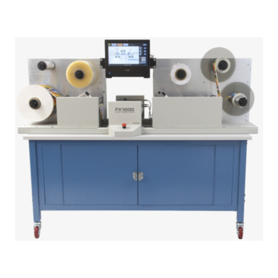
Section 2.2: Indentifying the Parts FX1200 Overview Touch Screen Computer Lamination Liner Mandrel Upper Take Up Mandrel (Optional) Waste Matrix Take Up Mandrel Lamination Mandrel Unwinder (Weeder) Lower Take Up Mandrel Supply Mandrel Lamination Station Slitter Station Cutter Mechanism Right Dancer Arm Left Dancer Arm... - Page 8 FX1200 Supply Side (Left) Core Engagement Knobs Laminate Guide Roller Structural Bar Nip Lever Left Side Nip Point / Third Media Roller First Media Guide Roller Lamination Roller Second Media Roller Nip Roller...
- Page 9 FX1200 Cutter Mechanism Pinch Roller Pressure Thumbscrew Carrier Thumbscrew Knife/Knife Holder Pinch Rollers Release Levers Pinch Roller Knurled Roller Right Cutter Guide Roller Left Cutter Guide Roller Reference Latch...
- Page 10 FX1200 Take Up Side (Right) Waste Matrix Take Up Mandrel (Weeder) Right Side Nip Point Slitter Blades Core Engagement Knobs Nip Lever Second Media Roller Slitter Rollers Media Guides Take Up First Media Guide Roller Nip Roller Waste Matrix Guide Roller Peel Roller...
- Page 11 Touch Screen Layout The touch screen includes four tabs that contain all of the information necessary to interact with all aspects of the FX1200. Setup Tab The setup tab is used to load cut files and set the number of knives to use in a job. Click Browse to load the cut file you want to run.
- Page 12 Run Job Tab This screen allows you to enable\disable mandrels, adjust tension levels on mandrels, score the face stock for easier start-up when weeding, release tension on the entire FX1200, Run 1 Copy of the cut or Run the entire job. Error conditions for the FX1200 will be displayed in the center of the screen on the Run Job tab.
- Page 13 Upper take up and lower take up mandrels have additional options for the wrap direction (Upper) and Edge Trim Mode (Lower). Advanced Tab The Advanced Tab contains advanced setup and calibration options. Do not edit these settings unless directed to do so by Primera tech support.
- Page 14 Help Tab The Help Tab contains this Operator’s Guide along with other tech support links and tools. Setup Video The Setup Video can be accessed at any time by pressing the Video Play Icon. This icon appears at various points in the software and will jump to the applicable section of the video depending on where you pressed the icon.
-
Page 15: Consumables And Accessories
Section 2.3 Consumables and Accessories Lamination Film A 500 foot length of high gloss lamination film is included with the FX1200. Primera recommends use of lamination film. Using lamination film has the following benefits. • Eliminates cutter and toner dust that would normally accumulate from cutting un- laminated material •... - Page 16 Note: When replacing knives always replace all knives in a particular knife set. Cutting knives can be ordered from Primera in matched sets depending on which color you need to replace. Knife holders hold the knives in place for cutting.
- Page 17 Generally, you should always use cores that are the same width as your finished roll (label width + liner margins). You may also use cores that are slightly smaller. Using larger width cores may create problems applying labels with some types of applicators.
-
Page 18: Section 3: Run A Job
Section 3: Run a Job Section 3.1: Load Roll and Splice to Web Tools Required: Scissors, Marker Notes Before Beginning: • It is highly recommended that you always leave enough footer on the end of your previous job to allow for easy splicing of new material. Approximately 12 feet of footer is necessary if you intend to cut and wind every label from your previous job. - Page 19 9. Align the web and new label roll with the guide. 10. Attach the new roll to the web. See graphic below. 11. Warning! Do not expose adhesive on the bottom of the web! It can stick to the left side nip point and wrap around the rubber roller.
-
Page 20: Setup Lamination (Optional)
3.2 Setup Lamination (Optional) Tools Required: Utility Knife Note: Before you attempt to attach the laminate film to the paper it is very helpful to add a paper starter strip to the end of laminate roll. This strip adds strength to the film and allows you to hold on to it without it folding over on itself. -
Page 21: Set Up Cutter
3.3 Set Up Cutter Note: Before setting up the cutter or making any cuts make sure the splice point is past the cutter mechanism. Also make sure any wrinkles in lamination are past the cutter. Warning: You should always cut smooth lamination to avoid damaging the cutter blades. A. -
Page 22: Set Up Multiple Knives
B. Set Up Multiple Knives Every cut file can be cut with a single knife. However, to increase throughput it is possible to use multiple knives on most cut files. To find out if a cut file can use multiple knives look at the Setup Cut File screen and check the knives available section at the top. - Page 23 3. Loosen the thumbscrew on the knife carrier indicated in the on-screen diagram. 4. Move the knife carrier forward or backward so that the reference latch can be moved into the notch on the knife carrier. Notch Reference Latch Thumbscrew Knife Carrier 5.
-
Page 24: Adjust Pinch Rollers
C. Adjust the Pinch Rollers Before making your first cut it may be necessary to adjust the pinch rollers. For now, just make sure that the rollers are spaced evenly across the web. 1. To move the pinch roller push down on the release latch. 2. -
Page 25: Find The Eyemark / Target
D. Find the Eyemark / Target With your knives in position, cut file loaded, pinch rollers positioned, lamination enabled (optional), you are now ready to make your first cut. These first cuts will allow you to analyze the quality and position of your cut. 1. -
Page 26: Adjusting Cut Depth/Pressure
E. Adjusting Cut Depth/Pressure 1. After running 1 copy, attempt to peel the label from the web. 2. Check for tear. If it tears you will need to increase the Cutter Pressure from the Setup Tab. Increase pressure in small increments to avoid over compensating and cutting through the liner. -
Page 27: Adjust Cut Position
F. Adjust Cut Position Cut lines not meeting offset across the web - The web is walking during the cut. Make sure guides 3 and 4 before and after the cutter are touching the web. - The cutter carriage belt is slipping. - Page 28 Cut appears crooked/skewed relative to the printed image. -The rear guide collar in position 3 needs forward adjustment. See section Cut appears crooked/skewed relative to the printed image. -The rear guide collar in position 4 needs forward adjustment. See section...
-
Page 29: Score The Face Stock For Weeding
G. Score the Face Stock for Weeding To make it easier to attach the waste matrix to the weeder, scoring the face stock of the web is recommended. This is not required but it will save on set up time. Always score the face stock after you have determined that the cut depth is correct. -
Page 30: Set Up The Weeder (Foam Weeder Roller)
Section 3.4 Set Up the Weeder Tools Needed: Utility Knife 1. Press “Test Cut file” repeatedly until the weeder score mark has reached or wraps around the lower take up mandrel. Depending upon how many Test Cut file sequences you ran, your weeder score mark may not have reached the lower take up mandrel or may have already wrapped around the mandrel several times. - Page 31 6. Pull the matrix from the liner and attach it to the Weeder. In this scenario the matrix will only hold together if you have laminated the labels. If the matrix does not easily pull, manually turn the take up mandrel with your right hand as you pull the matrix with your left hand.
- Page 32 Installation Instructions: 1. The foam roller has a slit along the entire length so that you can push it over the weeder roller. Push Foam Over Foam Roller Weeder Roller Weeder Roller 2. Rotate the foam roller so the slit is facing up.
-
Page 33: Set Up The Slitter
Section 3.5: Set Up the Slitter 1. Seven blades are preinstalled in the retracted position in your FX1200. The FX1200 slitter station allows you retract or engage slitting blades without removing them from the unit. You will need to decide how many to engage to slit your labels. For example, depending on what type of applicator will be used you may need to slit and remove edge waste. - Page 34 3. Loosen the thumbscrew on the blade housings you intend to engage. For optimal safety, it is recommended to use a plier to loosen the blade housing thumb and move them into the engaged position. View from Back of unit Note: Before deciding which blades to engage make sure that the blade can actually be...
- Page 35 8. Loosen the thumbscrews for the engaged slitters. Line them up with the correct positions between the die cut labels. 9. Once the blades are in the correct position, push the slitter station all the way closed. The blades will puncture the media once the slitter station is locked into place. Replacing or Rotating Blades If a blade becomes dull you will need to rotate the blade to one of the four cutting corners.
-
Page 36: Set Up The Take Up Mandrel
3.6 Set Up the Take Up Mandrels You can configure the take up mandrels in many ways. The instructions below illustrate the recommended method assuming a two column cut wrapped onto two separate rolls on the upper take up mandrel with the edge waste trimmed and rolling over the lower take up mandrel. Additional configurations include: Edge waste wrap. - Page 37 Edge Waste to Weeder. This involves running the waste directly from the Take Up Guide Roller to the underside of the Waste Matrix Take Up roll. This method will increase the size of the waste matrix more quickly and can cause problems for some types of cuts that require very even pulling force to properly pull the matrix.
- Page 38 7. Remove the waste label core from the lower take up mandrel. 8. Place a new core on the lower take up mandrel. 9. Feed the edge trim waste over the new core and into a waste basket. 10. Set the lower take up mandrel to Edge Trim mode. This mode turns the lower take up mandrel to help the edge trim waste into the waste basket with out tripping the web break detection that would normally be enabled.
-
Page 39: Run Job, Evaluate Tension And Adjust Guides
3.7 Run Job and Evaluate Tension and Guides You are now ready to run your job. Go to the Run Job Tab. Press Run. You will be presented with several options: Number of Copies. Touch the box to enter the number of copies. The number of copies relates to the number of cut pages. - Page 40 Note on Media Environment: 50% humidity and 72 degrees Fahrenheit is the optimal conditions for both storage and use of label stock. Store label stock in protective plastic wrappings. Rewrap partially used stock. Do not store stock directly on concrete floors. Label stock should be conditioned in this environment for 72 hours prior to use.
-
Page 41: Adjust Guides
The guide collars greatly affect how straight the web feeds through the FX1200. The guide collars are adjusted at the factory for use with the paper stock sold by Primera. However, any time you use a new roll there is a possibility that the width of the material is slightly different than the last roll. - Page 42 1. Guides 3 and 4 directly before and after the cutter should be touching the web. There should be no ability for the paper to move at these points. These guides should be adjusted if there appears to be a skewed cut. Depending on the direction of the skew you would need to adjust Guide 3 or 4 forward.
-
Page 43: Section 4: Creating Cut Files In Ptprint (Plt/Hpgl)
Section 4: Creating Cut Files in PTPrint (PLT) If you have a CX1200 and are using PTPrint, there are three methods that can be used to create a cut file. Import Die Line (Recommended). This method involves creating the cut line in your design software and importing it into PTPrint along with the label. - Page 44 4. Open the swatches windows, click the new swatch icon. 5. A New Color Swatch will be created. 6. Double click on it to open the swatch options. 7. Rename the swatch FXCUT. 8. Set the Color Type to “Spot Color.” 9.
- Page 45 If you change the layout of the graphics you must recreate the cut file or the cut will not align to the graphics. Important Note: You must have the latest version of PTPrint for this procedure to work. Download the latest version from the following location on the Primera website. Follow the installation instructions provided on the website. http://www.primera.com/downloads/support/CX1200/CX1200.html...
-
Page 46: Die Cut
4.2 Die Cut This method allows you to create standard shape cut lines such as circles, squares and rectangles within PTPrint. Use this method when no cut line has been created in the design software or when the source file EPS is not available and you must use flat files such as JPG, BMP or TIFF. - Page 47 4. Now you can set the various settings that determine where the cut will be. • Set the color of the cut. This is just for viewing purposes. • Set the shape. • Set the size to correspond to the size of the label that you input in the layout wizard.
-
Page 48: Contour Cut
4.3 Contour Cut This method senses the edge of the printed label and attempts to draw the cut line based on this information. Use this as a last resort when no EPS source file is available and the cut file necessary is a non standard shape. - Page 49 5. Below is an example of edge sensitivity set too low. Notice how the contour line invades the image on the left side. This is because the image is very light in that area. 6. To retry the edge detection simply click Apply again. Note: The object must stay selected for the contour toolbar and the apply button to be visible.
- Page 50 8. In this case, 252 was the correct number to choose. Now the contour line follows the outer border of the image correctly. 9. To add a bleed to the image adjust the border value on the contour cut tool bar. Click Apply again.
- Page 51 10. In rare cases you may want to extend the contour lines inside the image. Check the Inside/Outside box to enable this feature. The threshold screen will appear. Enter the desired value. Click OK. Notice how the contour line traces the "Pinot Noir" letters inside the image.
-
Page 52: Cut Settings
4.4 Cut Settings Before creating a cut file you can adjust the Plotting Defaults and the Tool Options. Both of these will affect how the knife travels along the cut path. They can be found on the Cut menu in PTPrint. -
Page 53: Label Layout Design Tips
4.5 Label Layout Design Tips When importing labels through the PTPrint layout wizard there are two items to consider that affect FX1200. • Number of Columns in PTPrint = Number of knives available for use. • Margins and horizontal gaps in PTPrint = Pinch Roller pressure effects. Using the optimal number of knives will increase the speed of the cut. -
Page 54: Section 5: Maintenance And Troubleshooting
Section 5: Maintenance and Troubleshooting 5.1. Replacing Knives – Knife Tracking When a knife is dull it will no longer cut through the label at maximum pressure. You can check the life of any knife set by clicking the “Track” button on the Setup – Setup Cut File Screen. Knives are tracked in linear feet. -
Page 55: Rethread The System (Paper Path)
5.2 Rethread the System (Paper Path) To rethread the system, press the Release Tension button. Use the Paper Path Diagram on the next page to manually rethread the system. To start open both the left and right nip points. You may find it useful to engage the nip rollers during the rethreading process at various points in order to prevent the media from slipping back. -
Page 57: Cleaning And Maintenance
5.3 Cleaning and Maintenance Basic periodic cleaning and maintenance is required to keep the FX1200 running smoothly. Clean Rubber Nip Point Rollers The nip point rollers are located on the left and right sides of the cutter. Adhesive from the edges of media can build up on these rollers. -
Page 58: Problem - Solution Table
5.4 Problem - Solution Table Problem Solution Vertical Target Error 1. The cutter sensor cannot find the - Error Message eyemark/target. Manually adjust the web so that the target is in the carrier window. (3.3D) 2. The print quality of the target may not be sufficient. - Page 59 Problem Solution There is a track of small bumps This is caused by the pinch rollers crushing the that can be seen running with the media against the knurled roller in the cutter. The entire length of the web. The pinch roller in combination with the knurled roller is bumps can be seen on the finished necessary in order to grab the paper and rapidly...
- Page 60 Problem Solution Finished labels or curling up or 1. Make sure the lamination mandrel is enabled if under. you have laminate installed. 2. If finished labels are curling or peeling up or under on the edges this is an indication that tension on the web is not balanced.
-
Page 61: Diagram - Web Orientation
5.5 Web Orientation/Target Specification... -
Page 62: Section 6: Specifications
Section 6: Specifications Input roll max. diameter: 12” (305mm) Output roll max. diameter: 12” (305mm) Minimum web width: 4.5” (114mm) Maximum web width: 8.5” (216mm) Maximum die cutting width: 8” (203mm) Minimum label length: 0.75” (19mm) Maximum label length: 24” (609mm) Throughput speed: Up to 4”... - Page 63 Decibel levels 72 dB - 98 dB depending on lamination film used. Dimensions: 78”W x 30”D x 56”H (198cmW x 76.2cmD x 142cmH) Weight (estimated): 498 lbs. (226 kg) +/- .020 inches Cut registration tolerance: Cut size tolerance: +/- .005 inches Power requirements: Note: This system has multiple power source requirements.
- Page 64 511242-070912...
Need help?
Do you have a question about the FX1200 and is the answer not in the manual?
Questions and answers