
Related Manuals for Exmark Ultra Vac Lazer Z AS


Summary of Contents for Exmark Ultra Vac Lazer Z AS
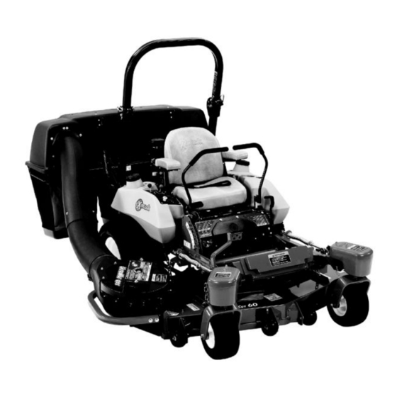
- Page 1 ULTRA VAC ® LAZER Z , LAZER Z ® ® LAZER Z XS AND ® LAZER Z AS MODELS ® For Ultra Vac Serial Nos. 720,000 & Higher (to fit Units 352,000 & Higher) Part No. 4500-192 Rev. A...
- Page 2 Exmark reserves the right to make changes or add improvements to its products at any time without incurring any obligation to make such changes to products manufactured previously. Exmark, or its distributors and dealers, accept no responsibility for variations which may be...
-
Page 3: Introduction
Introduction CONGRATULATIONS on the purchase of your Exmark Ultra Vac. This product has been carefully designed and manufactured to give you a maximum amount of dependability and years of trouble-free operation. This manual contains operating, maintenance, adjustment, and safety instructions for your Exmark... -
Page 4: Table Of Contents
Contents Introduction ... 3 Safety ... 5 Safety Alert Symbol ... 5 Safe Operating Practices ... 5 Safety and Instructional Decals ... 8 Specifications ... 10 Model Numbers ... 10 Systems ... 10 Dimensions... 10 Torque Requirements ... 11 Product Overview ... 11 Operation ... -
Page 5: Safety
• Evaluate the terrain to determine what accessories and attachments are needed to properly and safely perform the job. Only use on machines approved by Exmark. • Wear appropriate clothing including safety glasses, substantial footwear, long trousers, and hearing protection. Do Not operate when barefoot or when wearing open sandals. -
Page 6: Slope Operation
Safety DANGER There are rotating blades in the blower and under the mower deck. Blade contact can cause serious operator or bystander injury or even death. • Do Not reach into blower unless rotation indicator has stopped. Disengage PTO, stop engine, remove key, wait for all moving parts to stop. -
Page 7: Maintenance And Storage
• Remove or mark obstacles such as rocks, tree limbs, etc. from the mowing area. Tall grass can hide obstacles. • Watch for ditches, holes, rocks, dips and rises that change the operating angle, as rough terrain could overturn the machine. •... -
Page 8: Safety And Instructional Decals
103-6606 • New safety signs may be obtained from your authorized Exmark equipment dealer or distributor or from Exmark Mfg. Co. Inc. • Safety signs may be affixed by peeling off the backing to expose the adhesive surface. Apply only to a clean, dry surface. Smooth to remove any air bubbles. - Page 9 Safety 103-3507 UV60 and UV6672 103-3508 LZUV52 Only...
-
Page 10: Specifications
Specifications Specifications Model Numbers Serial Nos: 720,000 and Higher LZUV52–Fits Lazer Z and Lazer Z AS with 52 inch deck. UV60–Fits Lazer Z, Lazer Z XP, Lazer Z XS, and Lazer Z AS with 60 inch deck. UV6672–Fits Lazer Z, Lazer Z XP, Lazer Z XS, and Lazer Z AS with 66 inch or 72 inch deck. Systems Bagging System •... -
Page 11: Curb Weight
Curb Weight: w/Ultra Vac 52 inch Deck-All 254 lb (115 kg) 60 inch Deck-SN 599,999 324 lb (147 kg) and Lower & All Lazer AS 60 inch Deck-SN 600,000 243 lb (110 kg) and Higher Air-Cooled (except AS) 60 inch Deck-SN 600,000 261 lb (118 kg) and Higher Liquid-Cooled 66 inch Deck-All... -
Page 12: Operation
Operation Operation Note: Determine the left and right sides of the machine from the normal operating position. Pre-Start Make sure you understand the controls, their locations, their functions, and their safety requirements. Ensure the blower, belt cover, bags, tube and hood are in good condition, properly attached, and latched. - Page 13 Figure 5 1. Clevis Pin 5. Belt Cover 2. Caster Arm Weight 6. Blower 3. Hairpin 7. Tube 4. Front Floorpan Weight 8. Bags 3. Remove the belt cover by loosening the knobs. For 60 inch and 66 inch units the outboard knob does not need to be removed completely to remove the belt cover.
-
Page 14: Bagger Installation For Bagging
Operation Note: The removable weights are heavy. Use care when lifting them. Make sure that you can hold them securely before lifting them. Use caution when positioning your hands so that you Do Not set them down on your hands or fingers. Note: The portions of the Ultra Vac bagger that are not bolted to the mower are designed to be installed or removed in their entirety. -
Page 15: Transporting
Figure 7 1. Clevis Pin 2. Hairpin 11. Units with removable floorpan weight: Tighten knob on weight assembly until the weight is clamped securely to the caster arm. 12. Hook weight plate assembly over the top of the weight mounting plates and secure with two hairpins as shown in Figure 8). -
Page 16: Loading A Unit
Operation WARNING Loading a unit on a trailer or truck increases the possibility of backward tip-over. Backward tip-over could cause serious injury or death. • Use extreme caution when operating a unit on a ramp. • Use only a single, full width ramp; Do Not use individual ramps for each side of the unit. -
Page 17: Maintenance
Maintenance Note: Determine the left and right sides of the machine from the normal operating position. WARNING While maintenance or adjustments are being made, someone could start the engine. Accidental starting of the engine could seriously injure you or other bystanders. Remove the key from the ignition switch, engage parking brake, and pull the wire(s) off the spark plug(s) before you do any... -
Page 18: Lubricate Grease Fittings
Maintenance Lubricate Grease Fittings Note: See chart for service intervals. 1. Stop engine, wait for all moving parts to stop, and remove key. Engage parking brake. 2. Lubricate fittings with NGLI grade #2 multi-purpose gun grease. Refer to the following chart for fitting locations and lubrication schedule. -
Page 19: Cleaning
Cleaning Clean Muffler and Rear Frame Area Service Interval: Before each use or daily Stop engine, wait for all moving parts to stop, and remove key. Engage parking brake. WARNING Operating engine parts, especially the muffler, become extremely hot. Severe burns can occur on contact and debris, such as leaves, grass, brush, etc. -
Page 20: Troubleshooting
Troubleshooting Troubleshooting Important: It is essential that all operator safety mechanisms be connected and in proper operating condition prior to mower use. When a problem occurs, Do Not overlook the simple causes. For example: starting problems could be caused by an empty fuel tank. The following table lists some of the common causes of trouble. - Page 21 • Attorney's fees. No Claim of breach of warranty shall be cause for cancellation or rescission of the contract of sale of any Exmark mower. Some states do not allow exclusions of incidental or consequential damages, so the above exclusions and limitations may not apply to you.
-
Page 22: Service Record
Service Record Date: Description of Work Done: Service Done By:... - Page 24 SEE EXMARK’S COMPLETE LINE OF ACCESSORIES MID-MOUNT RIDING ACCESSORIES CUSTOM RIDE SEAT SUSPENSION SYSTEM DECK LIFT ASSIST KIT HITCH KIT LAZERLOCKER LIGHT KIT MICRO-MULCH SYSTEM OPERATOR CONTROLLED DISCHARGE OUT-FRONT RIDING ACCESSORIES CUSTOM RIDE SEAT SUSPENSION SYSTEM DUAL-TAIL WHEEL FLOOR PAN EXTENDER...
Need help?
Do you have a question about the Ultra Vac Lazer Z AS and is the answer not in the manual?
Questions and answers