Table of Contents
Advertisement
Quick Links
Advertisement
Table of Contents

Related Manuals for TYAN Transport GT24 (B2932


Summary of Contents for TYAN Transport GT24 (B2932
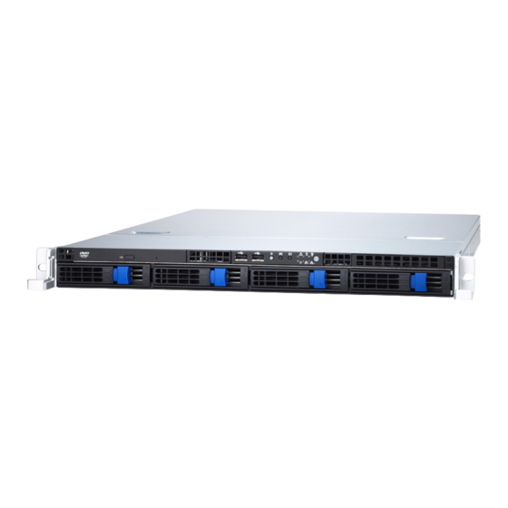
- Page 1 Transport GT24 B2932 Service Engineer’s Manual...
- Page 3 TYAN retains the right to make changes to product descriptions and/or specifications at any time, without notice. In no event will TYAN be held liable for any direct or indirect, incidental or consequential damage, loss of use, loss of data or other malady resulting from errors or inaccuracies of information contained in this document.
- Page 4 Federal Communications Commission (FCC) Notice for the USA Compliance Information State- ment (Declaration of Conformity Procedure) DoC FCC Part 15: This device complies with part 15 of the FCC Rules Operation is subject to the following conditions: 1) This device may not cause harmful interference, and 2) This device must accept any interference received including inter- ference that may cause undesired operation.
- Page 5 About this Manual This manual provides you with instructions on installing your Transport GT24, and consists of the following sections: Chapter 1: Provides an Introduction to the Transport GT24 B2932 barebones, packing list, describes the external components, gives a table of key compo- nents, and provides block diagrams of the system.
- Page 6 SAFETY INFORMATION Before installing and using the Transport GT24, take note of the fol- lowing precautions: – Read all instructions carefully. – Do not place the unit on an unstable surface, cart, or stand. – Do not block the slots and opening on the unit, which are pro- vided for ventilation.
-
Page 7: Table Of Contents
Chapter 1:Overview 1.1 About the TYAN Transport GT24 B2932 ....1 1.2 Product Models ........2 1.3 Features . - Page 8 3.5 Replacing the Slim DVD-ROM ......44 3.6 Replacing the LED Control Board ......46 3.6.1 M1003 LED Control Board Features.
-
Page 9: Chapter 1:Overview
About the TYAN Transport GT24 B2932 Congratulations on your purchase of the TYAN Transport GT24 B2932, a highly-optimized rack-mountable barebone system. The TYAN Transport GT24 B2932 offers the latest in dual processor server systems, providing a rich feature set and incredible performance. Leveraging advanced technol- ®... -
Page 10: Product Models
Product Models Model HDD Bays Motherboard Supported Backplane Removable, 4-port B2932G24W4H SAS/SATA S2932WG2NR 4 HDDs SAS/SATA Removable, 4-port B2932G24V4H SATA S2932WG2NR-L-B 4 HDDs SAS/SATA B2932G24W4H B2932G24V4H Chapter 1: Overview... -
Page 11: Features
Motherboard Back I/O Ports • B2932G24V4H • One (1) PS/2 Keyboard and one (1) – TYAN Thunder n3600M mouse ports 2932G2NR-L-B • One (1) 9-pin UART Serial port • B2932G24W4H • One 15-pin VGA port – TYAN Thunder n3600M •... - Page 12 • Automatic fan speed control • FCC Class B (Declaration of Con- • Support Tyan Server Management formity) (TSM) • CE (Declaration of Conformity) • Option TYAN SMDC M3291, IPMI Environment Temperature v2.0 compliant remote server man- • Operating temperature (5 C~35 agement kit •...
-
Page 13: Unpacking
If any items are missing or appear damaged, contact your retailer or browse to TYAN’s Web site for service: http://www.tyan.com. The Web site also provides information on other TYAN prod- ucts, plus FAQs, compatibility lists, BIOS settings, and more. Power Cords... - Page 14 Rail Kit Rear Front Mounting Bracket x 4 Sliding Brackets Front L-Bracket x 2 Rear L-Bracket x 2 Mounting Ears & Screws Sliding Rails x 2 Screws Kit FDD Kit FDD Cable FDD Installing Rails & Screws FDD Backplane Cable Chapter 1: Overview...
-
Page 15: Fru Parts
1.4.2 FRU Parts Model Item Quantity Description Number Standard Parts S2932G2NR TF-Motherboard Tyan S2932G2NR-L- -L-B B(B2932G24V4H SKU) Motherboard S2932WG2 TF-Motherboard Tyan S2932WG2NR (B2932G24W4H SKU) Chassis Unit CCHA-0030 TF-CHASSIS UNIT;GT24 TF-Delta 650W TDPS -650CB C 1U CPSU-0112 Power Supply TF-Delta 600W TDPS -600CB 1U... - Page 16 Model Item Quantity Description Number TF-SATA data cable, L=250mm CCBL-0326 HS/180-HS/180 TF-Front panel Control Board Cable CCBL-0340 HS2*14Pins/HS2*14 L=250mm(Flat Cable) CCBL-0409 TF-TYFP I Cable CCBL-0419 TF-TYFP II Cable CCBL-0433 TF-CD-ROM ATA66 FLAT CABLE Cable Set TF-CD-ROM Power cable S4P/S4P CCBL-0420 L=80mm CCBL-0652 TF-FAN CABLE L=160mm...
-
Page 17: About The Product
About the Product This section contains the hardware diagrams and a block dia- gram of the GT24 system. 1.5.1 System Front View Warning LED Reset switch NMI switch HDD activity LED ID Switch Power LED ID LED Power switch USB ports 2 x LAN LEDs DVD-ROM Drive Hard Drive Bay x 4... -
Page 18: Led Definition
1.5.3 LED Definition Front Panel Color State Description Power Green Power ON Power OFF HDD Activity Amber Random Blinking HDD access activity No disk activity LAN1/LAN2 Activity Green LAN linked Green Blinking LAN accessing No LAN linked Warning Fan fails / Abnormal shut down Normal ID LED... - Page 19 Rear I/O LED Color State Description LAN1/LAN2 Linkage/ Activ- Green 10Mb/100Mb/1000Mb ity (Left Side) Green Blinking linked 10Mb/100Mb/1000Mb activity No LAN linked and activity LAN1/LAN2 Linkage/ Activ- Yellow 1 Blinking 10Mb mode ity (Right Side) 2 Blinking 100Mb mode 3 Blinking 1000Mb mode NO LAN linked and activity Note: In 10 Mbps, the Right LED blinks yellow once in repeat and continuous action.
-
Page 20: System Internal View
1.5.4 System Internal View B2932G24W4H FAN5 FAN4 FAN3 FAN2 FAN1 FAN7 FAN6 1. PCI-Slot (with riser card 5. Adapter Board M2083) 6. SAS/SATA Backplane 2. EPS 12V Power Supply 7. LED Control Board Cable 3. CPU Sockets 8. Four SATA HDDs 4. - Page 21 B2932G24V4H FAN5 FAN4 FAN3 FAN2 FAN1 FAN7 FAN6 1. PCI-Slot (with riser card 5. Adapter Board M2083) 6. SAS/SATA Backplane 2. EPS 12V Power Supply 7. LED Control Board Cable 3. CPU Sockets 8. Four SATA HDDs 4. System Fans (Top-Right to 9.
-
Page 22: Gt24-B2932 System Block Diagram
1.5.5 GT24-B2932 System Block Diagram SDRAM DDR2 SDRAM DDR2 SDRAM DDR2 SDRAM DDR2 SDRAM DDR2 SDRAM DDR2 SDRAM DDR2 SDRAM DDR2 slot SDRAM DDR2 SDRAM DDR2 SDRAM DDR2 SDRAM DDR2 SDRAM DDR2 SDRAM DDR2 SDRAM DDR2 SDRAM DDR2 Chapter 1: Overview... -
Page 23: S2932 Board Parts, Jumpers, And Connectors
Pin 2-3 closed: Disable - SAS Enable/Disable Jumper Pin 1-2 closed: Enable (Default) Pin 2-3 closed: Disable IPMB Pin Header J39/J63 TYAN Front Panel 2 Connector (for Barebone) SMDC Connector LCM Pin Header (for Barebone) Front Panel USB2.0 Connector SGPIO Header (for Barebone) - Page 24 Chapter 1: Overview...
-
Page 25: Chapter 2:Setting Up
Chapter 2: Setting Up 2.0.1 Before You Begin This chapter explains how to install the CPU, CPU heatsink, memory modules, and hard drives. Instructions on inserting a PCI-E card are also given. Take note of the precautions mentioned in this section when installing your system. -
Page 26: Precautions
2.0.4 Precautions Components and electronic circuit boards can be damaged by discharges of static electricity. Working on a system that is connected to a power supply can be extremely dangerous. Follow the guidelines below to avoid damage to the Transport GT24 or injury to yourself. •... -
Page 27: Rack Mounting
Rack Mounting After installing the necessary components, the Transport GT24 can be mounted in a rack using the supplied rack mounting kit. Rack mounting kit Sliding Rails x 2 Sliding Brackets x 4 (Front x 2, Rear x 2) Mounting Ears (including screws) x 2 Screws Kit x 1 Mounting Brackets x 4 2.1.1 Installing the Server in a Rack... - Page 28 Installing the Inner Rails to Chassis 1. Screw the mounting ear to each side of Transport GT24 as shown using 2 screws from the supplied screws kit. Mounting Ears 2. Draw out the inner rails from rail assembly. Install inner rails to left and right sides of chassis using 1 M4-4L(A) screw for each side.
- Page 29 4. Locate the front and rear brackets. Rear Bracket x2 Front Bracket x2 5. Secure the front bracket to outer rail with 2 M4-4L(A) screws. 6. Reserve the distance same as in Step 2 on rear bracket. Secure the rear bracket to outer rail with 2 M4-4L(A) screws.
- Page 30 Rackmounting the Server 8. Draw out the middle rail to the latch position. 9. Lift the chassis and then insert the inner slide rails into the middle rails. 10. Push the chassis in and press the latch key (A). Then push the whole system into the rack (B).
- Page 31 11. Secure the mounting ears of chassis to the rack with 2 M5-15L(C) screws. NOTE: To avoid injury, it is strongly recommended that two people lift the Transport GT24 into the place while a third per- son screws it to the rack. Chapter 2: Setting Up...
-
Page 32: Installing Motherboard Components
Installing Motherboard Components This section describes how to install components on to the motherboard, including CPU, memory modules and PCI-E card. 2.2.1 Removing the Chassis Cover Follow these instructions to remove the Transport GT24 chassis cover. 1. Release the screw on the back side. Then slide the chas- sis cover in the direction of arrow. -
Page 33: Installing The Cpu, Heatsink And Air Duct
2.2.2 Installing the CPU, Heatsink and Air Duct Follow these instructions to install the CPU, CPU heatsink and air duct. 1. After removing the pre-installed air duct, locate the CPU sockets. 2. Take off the CPU protection cap. 3. Pull the CPU lever up to unlock the CPU socket. Chapter 2: Setting Up... - Page 34 4. Open the socket in the direction as shown. 5. Place the CPU in the CPU socket, ensuring that pin 1 is located as shown below. 6. Close the socket and press the CPU socket lever down to secure the CPU. Chapter 2: Setting Up...
- Page 35 7. Place the heatsink on top of the CPU and screw into place as shown. 8. Place and screw the air duct back. Chapter 2: Setting Up...
-
Page 36: Installing The Memory
2.2.3 Installing the Memory Follow these instructions to install the memory modules on the motherboard. 1. Locate the memory slots on the motherboard. 2. Press the memory slot locking levers in the direction of the arrows as shown in the following illustration. 3. - Page 37 4. Insert the memory module into the slot as shown. When inserted properly, the memory slot locking levers lock automatically onto the indentations at the ends of the module. Attention When Installing the Memory! Please be noticed always install memory DIMMs in pairs starting from CPU1_DIMM0 and CPU1_DIMM1 and CPU2_DIMM0 and CPU2_DIMM1.
- Page 38 Refer to the table for supported DDR populations, and check the user’s manual for the details. (Note: X indicates a populated DIMM slot) Single CPU Installed Dual CPU installed (CPU1 only) (CPU1 and CPU2) Population Option CPU1_DIMM0 CPU1_DIMM1 CPU1_DIMM2 CPU1_DIMM3 CPU1_DIMM4 CPU1_DIMM5 CPU1_DIMM6...
-
Page 39: Installing A Pci-E Card
2.2.4 Installing a PCI-E Card There is one PCI-E slot on the rear panel of GT24. Refer to the procedures below for PCI-E installation. 1. Push the tab of PCI-E slot on the rear panel in the direc- tion as shown to release the bracket. 2. - Page 40 4. Insert the PCI-E card as shown. 5. Push the tab of PCI-E slot in the direction as shown to fix PCI-E card. Chapter 2: Setting Up...
-
Page 41: Installing The Hard Drives
Installing the Hard Drives The TYAN Transport GT24 barebone system supports SAS/SATA hard drives. Follow these instructions to install a SAS/SATA hard drive for model GT24 B2932. 1. Press the locking lever latch in the direction of arrow (A) and then pull the locking lever open (B). - Page 42 4. Using 4 HDD screws to secure the HDD. 5. Reinsert the drive tray into the chassis (A), ensuring that the drive tray is completely inserted into the chassis (B). 6. Pressing the locking lever to secure the hard drive tray. Chapter 2: Setting Up...
-
Page 43: Installing The Slim Fdd (Option)
Installing the Slim FDD (Option) 1. Locate the two FDD rails and screws from the FDD kit. Secure the two rails to FDD using four screws. FDD Rails & Screws 2. Connect the FFC cable to FDD. 3. Using a screw driver to pull open the door of FDD tray. 4. - Page 44 5. Connect the FFC cable to the connector on M1012 adapter board. 6. Locate the FDD cable from FDD kit. Connect the wrinkle side to the connector on M1012 adapter board. Refer to the picture below for the correct direction. For Mainboard For M1012 7.
-
Page 45: Chapter 3:Replacing Pre-Installed Components
Chapter 3: Replacing Pre-Installed Components Introduction This chapter explains how to replace pre-installed compo- nents including the motherboard, LED control board, DVD- ROM drive, M1012 adapter board, SAS/SATA backplane, and power supply. Take note of the precautions in this section when installing your system. -
Page 46: Precautions
3.1.3 Precautions Components and electronic circuit boards can be damaged by static electricity. Working on a system that is connected to a power supply can be extremely dangerous. Follow the guidelines below to avoid damage to the Transport GT24 or injury to yourself. -
Page 47: Disassembly Flowchart
Disassembly Flowchart The following flowchart outlines the disassembly procedure. Rear Components DIMMs Chassis rear cover CPU/heatsink assembly PCI card Mainboard Mainboard Power supply Front Components Chassis rear cover PCBs DVD-ROM M1012 Control Board Adapter Board HDD Backplane Chapter 3: Replacing Pre-Installed Components... -
Page 48: Removing The Cover
Removing the Cover Before replacing any parts you must remove the chassis cover. Follow these instructions to remove the cover of the Transport GT24 chassis cover. 1. Release the screw on the back side. Then slide the chas- sis cover in the direction of arrow. 2. -
Page 49: Replacing Motherboard Components
Replacing Motherboard Components Follow these instructions to replace motherboard compo- nents, including the motherboard. 3.4.1 Disconnecting All Motherboard Cables Before replacing the motherboard or certain components, remove cables connected to the motherboard. Follow these instructions to remove all motherboard cabling. 1. - Page 50 2. Disconnect DVD-ROM drive cable, SAS/SATA hard drive cables, USB, TYFP I, TYFP II, and Fan cable. Refer to the mainboard layout for the locations. Chapter 3: Replacing Pre-Installed Components...
-
Page 51: Removing The Motherboard
3.4.2 Removing the Motherboard Follow these instructions to remove the motherboard from the chassis when all add-on components have been removed. 1. Remove two screws securing the link-bar to the chassis. 2. Remove ten screws securing the motherboard to the chassis. -
Page 52: Replacing The Slim Dvd-Rom
Replacing the Slim DVD-ROM Follow these instructions to replace the DVD-ROM. 1. Remove power and data cables from the slim DVD-ROM adapter. 2. Press the tab in the directions as shown to release the DVD-ROM drive. 3. The DVD-ROM drive will be freed from the drive bay after pressing the tab. - Page 53 4. Remove two screws that secure DVD-ROM drive to the bracket. 5. Replace the DVD-ROM drive. 6. Secure DVD-ROM to the bracket using two screws. Then replace the unit into the drive bay and connect the DVD- ROM power and data cables. Chapter 3: Replacing Pre-Installed Components...
-
Page 54: Replacing The Led Control Board
Replacing the LED Control Board Follow these instructions to remove the LED control board. 1. Remove the two screws securing the LED control board to the chassis. 2. Lift the LED control board unit free from the chassis. 3. Unplug the USB cable from the connector. Chapter 3: Replacing Pre-Installed Components... - Page 55 4. Unplug the ribbon cable from the connector. 5. Remove the three screws securing the LED control board to the bracket. 6. Lift the LED control board free from the chassis. After replacement, insert the unit to the chassis following the above procedures in reverse.
-
Page 56: M1003 Led Control Board Features
3.6.1 M1003 LED Control Board Features J2: Front Panel Connector J1: USB Connector Chapter 3: Replacing Pre-Installed Components... -
Page 57: M1003 Led Control Board Connector Pin Definition
3.6.2 M1003 LED Control Board Connector Pin Definition J1 USB Connector VCC5 VCC5 USB1- USB0- USB1+ USB0+ KEY PIN J2 Front Panel Connector HDLED+ HDLED- RESET+ RESET- PW_LED+ PW_LED- WLED+ WLED - ICH_SMBDAT ICH_SMBCLK EXT_INT VOLTAGE5 V5SB INTRU# PWR_SW+ PWR_SW- LAN1_LED+ LAN1_LED - LAN2_LED+... -
Page 58: Replacing The M1012 Adapter Board
Replacing the M1012 Adapter Board 1. Remove all the cables connected to the adapter board, including front panel, TYFP, FAN, and DVD-ROM power cables. Refer to page 47 for the location 2. Remove the six screws to release the adapter board. Chapter 3: Replacing Pre-Installed Components... -
Page 59: M1012 Adapter Board Features
3.7.1 M1012 Adapter Board Features J1: Front Panel Connector J16: LCM Connector J14: Fan Tach Connector FDD1: Standard Floppy Connector J7:Fan Tach & PWM Connector J3: LAN/ID LED Connector JP1: Fan Input Select Connector J19: DVD-ROM Power Connector J5: Fan Connector J9: Fan Connector J11: Fan Connector J10: Fan Connector... -
Page 60: M1012 Adapter Board Connector Pin Definition
3.7.2 M1012 Adapter Board Connector Pin Definition J1 TYFP Front Panel Connector HDLED+ PW_LED+ HDLED - PW_LED - RESET- PWR_SW+ RESET+ PWR_SW - VOLTAGE5 WLED+ EXT_INT WLED- V5SB KEY PIN ICH_SMBDAT ICH_SMBCLK INTRU# J2 Front Panel Connector HDLED+ HDLED- RESET+ RESET- PW_LED+ PW_LED-... - Page 61 J3 LAN/ID LED Connector LAN1_LED+ LAN1_LED- LAN2_LED+ LAN2_LED- LAN3_LED+ LAN3_LED- ID_LED+ ID_LED- ID_SW+ ID_SW- KEY PIN FAN Signal Related Connector Pin Definition NOTE: The FAN signal naming is based on HW circuit design only. It might be different from the system fan naming. J4 Fan TACH &...
- Page 62 J13 Fan TACH Connector FAN1_TACH FAN2_TACH FAN3_TACH KEY PIN J14 Fan TACH Connector FAN1_TACH FAN2_TACH FAN3_TACH FAN4_TACH FAN5_TACH FAN6_TACH FAN7_TACH FAN8_TACH FAN9_TACH FAN10_TACH KEY PIN J6 Fan Connector FAN1_12VPWM FAN1_TACH FAN2_TACH FAN2_12VPWM Chapter 3: Replacing Pre-Installed Components...
- Page 63 J10 Fan Connector FAN3_12VPWM FAN3_TACH FAN4_TACH FAN4_12VPWM J11 Fan Connector FAN5_12VPWM FAN5_TACH FAN6_TACH FAN6_12VPWM J9 Fan Connector FAN7_12VPWM FAN7_TACH FAN8_TACH FAN8_12VPWM Chapter 3: Replacing Pre-Installed Components...
- Page 64 J5 Fan Connector FAN9_12VPWM FAN9_TACH FAN10_TACH FAN10_12VPWM J15 & J16 LCM Connectors LCM_+5V LCM_SIN KEY PIN LCM_+5VSB LCM_SOUT JP1 Fan Input Select Connector Pin1 & Pin2 Close Fan PWM signal from J8 Pin2 & Pin3 Close Fan PWM signal from J4, J7 &...
-
Page 65: Replacing The Sas/Sata Backplane
Replacing the SAS/SATA Backplane NOTE: The procedures for replacing SAS/SATA backplanes are the same. 1. Remove the 3 screws securing the adapter board to the chassis. 2. Grab the two labels to lift the adapter board. Chapter 3: Replacing Pre-Installed Components... - Page 66 3. Remove the ten screws that secure the bracket to the adapter board. 4. Release the adapter board free from the bracket. 5. Replace the unit to the chassis following the reverse pro- cedures from step 1 to 4 after done. Chapter 3: Replacing Pre-Installed Components...
-
Page 67: Sas/Sata Backplane (M1208) Features
3.8.1 SAS/SATA Backplane (M1208) Features U4, SAS/SATA4 Connector U3, SAS/SATA3 Connector U2, SAS/SATA2 Connector HDD Access LED HDD Power LED U1, SAS/SATA 1 Connector Chapter 3: Replacing Pre-Installed Components... - Page 68 PW1 Power Connector PW2 Power Connector J4, SAS/SATA 4 Connector J3, SAS/SATA 3 Connector J2, SAS/SATA 2 Connector J7, SAS Fault LED J1, SAS/SATA 1 Connector Connector Chapter 3: Replacing Pre-Installed Components...
-
Page 69: Replacing The Power Supply
Replacing the Power Supply 1. Remove the two screws that secure the power supply to the chassis. 2. Remove the screw that secure the power supply to the chassis 3. Lift the power supply free from the chassis. 4. Place a new power supply in position in the chassis and secure in place with the three screws. -
Page 70: Appendix I: Bios Differences
Appendix I: BIOS Differences The BIOS of B2932 is similar to the BIOS of S2932. There is only one menu different. You may refer to the attached moth- erboard manual for the complete BIOS information. The dif- ferences between B2932 and S2932 is on the “Advanced/Hardware Health Information”... - Page 71 S2932 Advanced/Hardware Health Information BIOS Setup Utility Advanced Hardware Health Configuration Enables Hardware Health Monitoring Device. H/W Health Function [Enabled] CPUFAN1, 2 FAN1,2 PWM Control [Disabled] FAN3, FAN4, FAN5 PWM Control [Disabled] FAN Fail LED Indicator [Disabled] Hardware Health Event Monitoring Select Screen Select Item Mainboard Voltages Report...
-
Page 72: Appendix Ii: Cable Connection Tables
Appendix II: Cable Connection Tables SAS/SATA Cable Table 1: GT24 B2932 HDD Drive Connect to Motherboard HDD1 SATA0/SAS0 HDD2 SATA1/SAS1 HDD3 SATA2/SAS2 HDD4 SATA3/SAS3 FAN Cable Table 2: System Fan to M1012 Adapter Board System Fan Connect to M1012 Fan 1 / Fan 6 J6 Fan Connector Fan 2 / Fan 7 J10 Fan Connector... - Page 73 Power Supply Cable Table 4: Power Supply to Motherboard Power Supply Connect to Motherboard P1 24-pin power cable PW1 24-pin connector P2 8-pin power cable PW2 8-pin connector P3 4-pin power cable PW3 4-pin connector Table 5: Power Supply to M1012 Adapter Board Power Supply Connect to M1012...
- Page 74 Table 10: M1012 Adapter Board to Motherboard M1012 Connect to Motherboard J1 Front Panel connector J64 TYFP I connector J3 LAN/ID cable J65 TYFP II connector...
-
Page 75: Appendix Iii: Installing Smdc Cards
Appendix III: Installing SMDC Cards The following provides you with the information on installing SMDC cards. You may refer to the following for installing M3289 or M3290 into HDD tray or chassis. Screws List Screw Size Quantity Flat #6-32 -5L B-type #6-32-5L Stand-off #6-32-13.5L... - Page 76 1. Fold up the cable. 2. a: Choose a HDD tray. b: Insert the cable into the rear of HDD tray. c: Pull the cable out. 3. Connect the cable to M3289.
- Page 77 4. Align M3289 in reverse with 4 “M1” stand-offs. Secure the SMDC with 4 screws as illustrated. 5. Secure M3289 onto HDD tray as illustrated. 6. Insert and secure the HDD tray. NOTE: For internal or dummy HDD tray, secure the HDD tray with 1 or 2 screws.
- Page 78 Installing M3290/M3291 into HDD tray 1. Secure a removable stand-off of 13.5mm to the location of “M2” stand-off as illustrated on SMDC bracket. 2. Secure M3290 in reverse to 4 “M2” stand-offs on bracket. 3. a: Choose a HDD tray. NOTE: Refer to the location of SMDC connector on mainboard for choosing a HDD tray.
- Page 79 4. a: Inset the cable into the rear of HDD tray. b: Connect the cable to M3290. c: Insert and secure HDD tray. 5. Arrange and connect the cable to SMDC connector on mainboard. Be careful not to block the air flow.
-
Page 80: Technical Support
(which can have expensive consequences). If these options are not available for you then Tyan Computer Corporation can help.Besides designing innovative and qual- ity products for over a decade, Tyan has continuously offered customers service beyond their expectations. - Page 81 RMA number should be prominently displayed on the outside of the shipping carton and the package should be mailed pre- paid. TYAN will pay to have the board shipped back to you. Transport GT24, B2932 Service Engineer’s Manual v1.0 Document part No. D1847-100...
Need help?
Do you have a question about the Transport GT24 (B2932 and is the answer not in the manual?
Questions and answers