
Subscribe to Our Youtube Channel
Related Manuals for TYAN Transport VX50 (B4985 Series


Summary of Contents for TYAN Transport VX50 (B4985 Series
- Page 1 Transport VX50 B4985 Series Service Engineer’s Manual Document ID: D1851-101 警告使用者: 這是甲類的資訊產品,在居住的環境中使用時,可能會造成射頻干 擾,在這種情況下,使用者會被要求採取某些適當的對策。...
- Page 3 TYAN retains the right to make changes to product descriptions and/or specifications at any time, without notice. In no event will TYAN be held liable for any direct or indirect, incidental or consequential damage, loss of use, loss of data or other malady resulting from errors or inaccura- cies of information contained in this document.
-
Page 4: Notice For Canada
Federal Communications Commission Notice for the USA Compliance Information State- ment (Declaration of Conformity Procedure) DoC FCC Part 15: This device complies with part 15 of the FCC Rules Operation is subject to the following conditions: 1) This device may not cause harmful interference, and 2) This device must accept any interference received including inter- ference that may cause undesired operation. -
Page 5: About This Manual
About this Manual This manual provides you with instructions on installing your Transport VX50-B4985. This manual consists of the following sections: Chapter 1: Provides an Introduction to the VX50-B4985 bare- bone, packing list, describes the external compo- nents, gives a table of key components, and provides block diagrams of the system. -
Page 6: Safety Information
Safety Information Before installing and using the Transport VX50-B4985, take note of the following precautions: • Read all instructions carefully. • Do not place the unit on an unstable surface, cart, or stand. • Do not block the slots or openings on the unit which are provided for ventilation. -
Page 7: Table Of Contents
Table of Contents Chapter 1: Overview 1.1 About the TYAN Transport VX50-B4985 ........1 1.2 Product Models ................1 1.3 Features ..................3 1.4 Unpacking ..................5 1.4.1 Box Contents................5 1.4.2 Accessories ................7 1.5 About the Product ................ 9 1.5.1 System Front View .............. - Page 8 3.1 Introduction .................. 49 3.1.1 Work Area................49 3.1.2 Tools ..................49 3.1.3 Precautions................50 3.2 Removing the Chassis Cover ............51 3.3 Replacing Motherboard Components .......... 52 3.3.1 Disconnecting All Motherboard Cables ........ 52 3.3.2 Replacing the Motherboard ........... 53 3.4 Replacing the DVD-ROM............
-
Page 9: Chapter 1: Overview
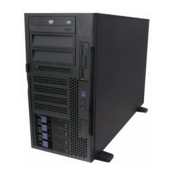
Chapter 1: Overview About the TYAN Transport VX50-B4985 Congratulations on your purchase of the TYAN Transport VX50-B4985, standalone or rack-mountable barebone ® system. This product supports up to eight AMD Opteron™ 8000 series 1207-pin processors and 128 GB of registered DRAM, offering exceptional computing power and simultaneous support of 32-bit and 64-bit applications. - Page 10 WARNING: This product is very heavy and should not be lifted by a single person. When installing this product in a rack, we recommend that at least two people lift the server while a third person guides it into place and tightens the fixings. Always use a suitable trolley or cart to transport the device.
-
Page 11: Features
SSI EEB 3.5 footprint (13 x 16-inch) M4985 CPU Board (8 way) • Supports up to 128GB of Registered, • TYAN M4985 (13” x 12”) ECC DDR2 667/533/400 four ranks memory module BIOS Expansion Slots • Phoenix 8Mbit LPC Flash ROM •... -
Page 12: Power Supply
Power Supply Regulatory • 1140W to 1620W, optional redundant • FCC Class B (Declaration of module Conformity) • 1140W for 4P (2+1 redundant with 1 • CE (Declaration of Conformity) Dummy module) Environment • 1620W for 8P (3+1 redundant) • Operating: 5ºC~35ºC System Cooling •... -
Page 13: Unpacking
Component Description B4985V50V4H-4P: Industry standard 5U chassis, (4) swappable HDD bays B4985V50V8H-8P: Industry standard 5U chassis, (8) swappable HDD bays Tyan Thunder n4250QE S4985G3NR motherboard (pre-installed) M4985 CPU board Standard DVD-ROM drive (pre-installed) Standard FDD drive (pre-installed) Chapter 1: Overview... - Page 14 Component Description M1209-P SAS/SATAII backplane (pre-installed) 2+1 redundant with 1 Dummy module / Total 1140W (for B4985V50V4H-4P) 3+1 redundant / Total 1620W (for B4985V50V8H-8P) (3) System cooling fans (pre-installed) 120 x 120 x 38 mm Chapter 1: Overview...
-
Page 15: Accessories
1.4.2 Accessories If any items are missing or appear damaged, contact your retailer or browse to TYAN’s Web site for service: http://www.tyan.com. The Web site also provides information on other TYAN products, plus FAQs, compatibility lists, BIOS settings, and more. - Page 16 Front Bezel Kit Bezel Door Mounting Ears x 2 with Keylock Keys Screws kit 4 x Chassis Foot Stands HDD Rails Kit Rail Kit Sliding Brackets x 4 Mounting Bracket x 4 Screws Kit Rail assembly Chapter 1: Overview...
-
Page 17: About The Product
About the Product This section contains hardware diagrams and a block diagram of the VX50-B4985 system. 1.5.1 System Front View See the diagram below for details of the front panel indicators and switches. B4985V50V4H-4P DVD-ROM Hot Swap 5.25-inch Internal drive HDD bays device bays HDD bays... -
Page 18: System Rear View
1.5.2 System Rear View 3 x Cooling Redundant 2 x USB ports VGA port fans Expansion slots Power supply Stacked PS/2 mouse Serial port 3 x RJ-45 AC input and keyboard ports LAN ports Chapter 1: Overview... -
Page 19: Led Definitions
1.5.3 LED Definitions Power on LAN2 LAN1 Status Color Description Power LED Green System is turned on Amber System is turned off Power off Amber HDD LED HDD access No disk activity LAN LED Blinking Green LAN is active No LAN linked ID LED Blue ID select on... -
Page 20: Motherboard (S4985) Layout
1.5.5 Motherboard (S4985) Layout Chapter 1: Overview... -
Page 21: S4985 Jumpers & Connectors
1.5.6 S4985 Jumpers & Connectors Jumper/Connector Function SMBUS Connector Fan Connector (for barebone use only) Clear CMOS Jumper - Pin 2-3 closed: Normal (Default) - Pin 1-2 closed: Clear NMI Header J30/J95 USB Front Panel Connector J30: USB2 J95: USB3 J101 COM2 Header J115... -
Page 22: S4985 Block Diagram
1.5.7 S4985 Block Diagram Chapter 1: Overview... -
Page 23: Cpu Board (M4985) Layout
1.5.8 CPU Board (M4985) Layout 1.5.9 M4985 Jumpers & Connectors Jumper/Connector Function Power Switch CPUFAN4/5/6/7 CPU Fan Connectors PWR1/2/3/4 Power Connectors SYSFAN8/9 System Fan Connectors Chapter 1: Overview... -
Page 24: M4985 Block Diagram
1.5.10 M4985 Block Diagram Chapter 1: Overview... -
Page 25: System Internal View
1.5.11 System Internal View 1. Memory slots 8. System fans 2. CPU sockets 9. SAS/SATA backplane 3. PCI-E x16 slots 10. Hard disk drive cradles 4. PCI slot 11. DVD-ROM cable 5. PCI-E x4 slots 12. DVD-ROM drive 6. SAS/SATA cables 13. - Page 26 Chapter 1: Overview...
-
Page 27: Chapter 2: Setting Up
Chapter 2: Setting Up Before You Begin This chapter explains how to install motherboard components including CPUs, CPU heatsinks, memory modules, CPU expansion board, and hard drives. Instructions on inserting a PCI card are also given. Take note of the precautions mentioned in this section when installing your system. -
Page 28: Precautions
2.1.3 Precautions Components and electronic circuit boards can be damaged by discharges of static electricity. Working on a system that is connected to a power supply can be extremely dangerous. Follow the guidelines below to avoid damage to the Transport VX50-B4985 or injury to yourself. -
Page 29: Installing Motherboard Components
Installing Motherboard Components This section describes how to install components on to the motherboard, including CPUs, memory modules and PCI cards. 2.2.1 Removing the Chassis Cover Follow these instructions to remove the Transport VX50- B4985 chassis cover. This step is required before any other procedures in this chapter can be undertaken. -
Page 30: Installing The Cpu And Heatsink
2.2.2 Installing the CPU and Heatsink Follow these instruction to install the CPU and CPU heatsink. NOTE: The system supports up to four CPUs. CPU0 must be installed first followed by CPU1, CPU2, and CPU3. 1. Locate the four CPU sockets on the motherboard. 2. - Page 31 4. Open the socket in the direction as illustrated. 5. Place the CPU in the socket, ensuring that pin 1 is correctly located. NOTE: The CPU will only fit in the socket one way. No force should be required to insert the CPU. 6.
- Page 32 7. Place the fan and heatsink on top of the CPU and attach with two screws as shown. NOTE: All heatsinks must be installed with fans facing the rear of the chassis to ensure efficient cooling. 8. Attach the fan power cable to the CPU fan pin header on the motherboard as shown.
- Page 33 Heatsink Coller Fan to Mother board Heatsink Cooler Fan Connects to Motherboard CPU FAN1 CPUFAN0 connector CPU FAN2 SYSFAN5 connector CPU FAN3 CPUFAN2 connector CPU FAN4 SYSFAN4 connector Heatsink Coller Fan to CPU Board Heatsink Cooler Fan Connects to CPU Board CPU FAN5 CPUFAN4 connector CPU FAN6...
-
Page 34: Installing The Memory
2.2.3 Installing the Memory Follow the instructions in this section to install memory mod- ules in your VX50 system. 1. Locate the memory slots on the motherboard. 2. Press the memory slot locking levers in the direction of the arrows as shown below. 3. - Page 35 When inserted properly, the memory slot locking levers lock automatically onto the indentations at the ends of the module. NOTE: Each bank memory of sockets is associated with one CPU. Memory will be recognized only when installed in a socket associated with an installed CPU. Attention When Installing the Memory! Refer to the following table for supported DDR2 populations.
-
Page 36: Installing The M4985 Cpu Expansion Board
2.2.4 Installing the M4985 CPU Expansion Board The CPU expansion board can accommodate a further four processors and 16 memory DIMMs. For B4985V50V4H-4P unit, when upgrading to eight CPU with a CPU expansion board, a further power supply module must be installed. 1. - Page 37 3. Use scotch tape to hold power cords and cables still. 4. Locate the HT slots on the S4985 motherboard. Put the CPU plate with the M4881 HT cards facing down into the chassis. Make sure to insert the M4881 HT cards into the HT slots completely.
- Page 38 5. Secure the CPU board with the plate in place with three screws as shown. Chapter 2: Setting Up...
- Page 39 6. Insert two further countersunk screws to secure the expansion board to the chassis as shown. 7. Connect the four power cables as shown. Chapter 2: Setting Up...
-
Page 40: Installing Pci-E/Pci Cards
2.2.5 Installing PCI-E/PCI Cards The VX50-B4985 has five PCI card slots: 2 x PCI-E x16 slots 2 x PCI-E x4 slots 1 x PCI slot Follow these instructions to install any of the above kinds of PCI cards. 1. Locate the PCI-E/PCI card slots on the motherboard. See “System Internal View”... - Page 41 3. Lift up the blanking plate. 4. Insert a PCI-E/PCI card into the appropriate slot, making sure it is firmly seated. Secure it with the screw removed in step 2. Chapter 2: Setting Up...
-
Page 42: Installing Hard Drives
Installing Hard Drives The VX50-B4985 supports up to eight hot-swappable SAS or SATA hard drives when two backplanes are installed. When the unit is B4985V50V4H-4P, with four hot-swap bays and one SATA backplane, follow the instructions below to install a further four hot-swap bays and a second SAS or SATA back- plane. - Page 43 3. Fix the storage backplane to the drive cradle using six screws. 4. Press the drive cradle release button and lower the drive housing back into place. Drive cradle release button 5. Connect power and data cables. Chapter 2: Setting Up...
-
Page 44: Installing Sas/Sata Hot Swap Drives
2.3.2 Installing SAS/SATA Hot Swap Drives 1. Pull out the locking lever (A) and pull the tray out of the chassis (B). 2. Remove the four screws holding the plastic spacer in the tray. 3. Remove the spacer from the tray Chapter 2: Setting Up... - Page 45 4. Place a SAS/SATA hard drive in the drive tray. 5. Secure the hard drive in place using four HDD screws. 6. Slide the drive tray back into the chassis and press the locking lever into place. NOTE: The VX50-B4985 (B4985V50V4H-4P) is shipped with a single SATA backplane and cables pre-installed.
-
Page 46: Installing Internal Hard Drives
Light pipe NOTE: Be careful not to damage the delicate light pipe when handling the HDD trays. 2.3.3 Installing Internal Hard Drives 1. Attach the supplied HDD rails to the both sides of a hard disk. Ensure that the locking clip faces the rear of the drive. - Page 47 3. Lift the drive housing to the vertical position as shown. 4. Slide the hard disk installed with the rails into place until it locks. 5. Press the drive housing release button and lower the drive housing back into place. 6.
-
Page 48: Rack Mounting
Rack Mounting After installing the necessary components, the Transport VX50-B4985 can be mounted in a rack using the supplied rack mounting kit. Rack mounting kit Sliding Rails x 2 Sliding Brackets x 4 Mounting Ears x 2 Screws Kit x 1 Mounting Brackets x 4 2.4.1 Installing the Server in a Rack Follow these instructions to mount the VX50-B4985 into an... - Page 49 Installing the Inner Rails to the Unit 1. Remove the black panels from the left and right sides of server to reveal the rail mounting screwholes beneath. 2. Screw the mounting ears to each side of the Transport VX50-B4985 as shown using two screws from the supplied screws kit.
- Page 50 Installing the Outer Rails to the Rack 4. Measure the distance between inner side of the front and rear mounting brackets in the rack. 5. Locate the sliding brackets. Sliding brackets 6. Secure the sliding brackets to the outer rails as shown, using the M4-4L (C) screws from the supplied screws kit.
- Page 51 7. Adjust the outer rails to fit the length of the rack (the distance measured in step 4). 8. Secure the assembled rail sets to the rack using two mounting brackets and four M5L8-H3 screws for each side. Use the top and bottom holes to fix the brackets to the rack frame.
- Page 52 Rackmounting the Server 10. Lift the server and slide it between the rails mounted in the rack. 11. Bolt the mounting ears to the rack using M5L15-H3 screws to secure the server in place. Notes: • When the rails are extended, they will lock. To shorten the rails again, you will need to operate the release mechanism in each rail.
-
Page 53: Standalone
Standalone The Transport VX50-B4985 can be used as a standalone device when fitted with the supplied plastic feet. When used as a standalone device, the feet must be fitted to prevent the unit from falling over. The four feet should be attached as follows: 1. -
Page 54: Fitting The Front Bezel Door
Fitting the Front Bezel Door A door is supplied with the Transport VX50-B4985 that can be used when the unit is rack mounted or standalone. Follow these instructions to attach the door. 1. Release the hinge clip from the top of the hinge section on the door 2. -
Page 55: Opening The Front Bezel Door
2.6.1 Opening the Front Bezel Door 1. Insert the front door key (packed in the screws kit in the accessory box) and rotate the key 90 degrees clockwise to unlock the door. 2. Pull the door in the direction of the arrow to open. Chapter 2: Setting Up... - Page 56 Chapter 2: Setting Up...
-
Page 57: Chapter 3: Replacing Pre-Installed Components
Chapter 3: Replacing Pre-installed Components Introduction This chapter explains how to replace all the pre-installed components including the motherboard, DVD-ROM drive, Floppy Disk Drive, SAS/SATA backplane, power supply, and system fans. Take note of the precautions in this section when installing your system. -
Page 58: Precautions
3.1.3 Precautions Components and electronic circuit boards can be damaged by static electricity. Working on a system that is connected to a power supply can be extremely dangerous. Follow the guidelines below to avoid damage to the Transport VX50- B4985 or injury to yourself. •... -
Page 59: Removing The Chassis Cover
Removing the Chassis Cover Follow these instructions to remove the Transport VX50- B4985 chassis cover. This step is required before any other procedures in this chapter can be undertaken. To remove the rear cover and expose motherboard components: 1. Press the two purple buttons on the retaining clips and lift them up. -
Page 60: Replacing Motherboard Components
Replacing Motherboard Components Follow these instructions to remove motherboard components and replace the motherboard. 3.3.1 Disconnecting All Motherboard Cables Before replacing the motherboard or certain components, remove cables connected to the motherboard. Follow these instructions to remove all motherboard cabling. 1. -
Page 61: Replacing The Motherboard
3. Disconnect the fan cables. 3.3.2 Replacing the Motherboard After removing all of those cables, follow these instructions to remove the motherboard from the chassis. 1. Remove the heat sinks and processors if installed. 2. Remove the nine screws that secure the motherboard to the chassis. -
Page 62: Replacing The Dvd-Rom
Replacing the DVD-ROM Follow these instructions to replace the DVD-ROM. 1. Remove the power and data cables from the rear of the DVD-ROM drive. 2. Remove the two thumbscrews that secures the DVD- ROM drive to the chassis. 3. Slide the DVD-ROM drive out of the chassis in the direction of the arrow shown. - Page 63 4. Install a new DVD-ROM drive in the drive bay and secure with two thumbscrews. 5. Replace the power and data cables. Chapter 3: Replacing Pre-installed Components...
-
Page 64: Replacing The Floppy Disk Drive
Replacing the Floppy Disk Drive Follow these instructions to replace the FDD in your VX50- B4985 system. 1. Loosen the two screws that secure the lower cover to the chassis of the VX50-B4985. Slide the cover back and remove it to expose the service port for the floppy disk drive. - Page 65 4. Slide the floppy disk drive out of the chassis. 5. Slide the new unit into place, secure with the two thumbscrews and replace the power and data cables. Chapter 3: Replacing Pre-installed Components...
-
Page 66: Replacing The Sas/Sata Backplane
Replacing the SAS/SATA Backplane Follow these instructions to replace the SAS/SATA backplane in your VX50-B4985 system. 1. Remove all the SATA hot swap HDD trays from the VX50-B4985. 2. Release the two screws holding the cradle locking bar in place (A) and remove the bar (B). 3. - Page 67 4. Lift the drive cradle to the vertical position as shown. 5. Remove the six screws to release the backplane. 6. Lift the backplane from the chassis. Drive cradle release button 7. Secure a new backplane in place with six screws. 8.
-
Page 68: Sas/Sata Backplane (M1209-P) Features
3.6.1 SAS/SATA Backplane (M1209-P) Features Front View Hot Swapped Hot Swapped HDD HDD Fail LED Power/Access LED J1 SAS 29 PIN Connector J2 SAS 29 PIN Connector J3 SAS 29 PIN Connector J4 SAS 29 PIN Connector Rear View JP3 2x4 pin header J13 Big 4P J14 Big 4P J5 SATA II 7 pin primary... -
Page 69: Sas/Sata Backplane (M1209-P) Header Pin Definition
3.6.2 SAS/SATA Backplane (M1209-P) Header Pin Definition JP3 External Hard disk Fail LED Pin out AF+1 AF-1 BF+1 BF-1 CF+1 CF-1 DF+1 DF-1 LED Definition Color State Description Hot Swappable HDD Green Power connected Tray Power/Access Green Blinking HDD access activity Power disconnected Hot Swappable HDD Amber... -
Page 70: Replacing The Redundant Power Supply
Replacing the Redundant Power Supply Follow these instructions to replace a redundant power supply unit in your VX50-B4985 system. 1. Release the thumbscrew of the redundant power supply and push the latch to the left. 2. Pull out the redundant power supply unit as shown. 3. -
Page 71: Replacing The System Fans
Replacing the System Fans Follow these instructions to replace the cooling fans in your VX50-B4985 system. See “Motherboard (S4985) Layout” on page 12 for the fan header locations. 1. Locate the fan connector on the motherboard for the fan you want to replace and unplug the fan cable as shown. 2. - Page 72 3. Pull the fan away from the chassis as shown and lift it free. 4. Replace the new fan into the chassis and secure with the four screws. 5. Reconnect the fan cable to the connector on the motherboard. Chapter 3: Replacing Pre-installed Components...
- Page 73 Appendix I: BIOS Differences The BIOS of B4985 is similar to the BIOS of S4985. There is only one menu different. You may refer to the attached motherboard manual for the complete BIOS information. The differences between B4985 and S4985 is on the “Advanced/Hardware Health Information”...
-
Page 74: Hardware Monitor
S4985 Advanced/Hardware Monitor Information PhoenixBIOS Setup Utility Advanced Hardware Monitor Item Specific Help CPU0 Temperature xxx ºC CPU1 Temperature xxx ºC CPU2 Temperature xxx ºC CPU3 Temperature xxx ºC Sys1 Temperature xxx ºC Sys2 Temperature xxx ºC Sys3 Temperature xxx ºC Sys4 Temperature xxx ºC Sys5 Temperature... - Page 75 Appendix II: Cable Connection Tables SAS/SATA Cables Table 1: VX50-B4985 Model M1209-P SAS/SATA Connects to Motherboard Backplane SATA1 SATA0 SATA3 SATA2 FAN Cables Table 2: System Fan to Motherboard System Fan Connects to Motherboard FAN 1 SYSFAN1 connector FAN 2 SYSFAN0 connector FAN 3 SYSFAN2 connector...
- Page 76 Table 4: Heatsink Cooler Fan to CPU Board Heatsink Cooler Fan Connects to CPU Board CPU FAN5 CPUFAN4 connector CPU FAN6 CPUFAN5 connector CPU FAN7 CPUFAN7 connector CPU FAN8 CPUFAN6 connector Power Supply Cables Table 5: Power Supply to Motherboard Power Supply Connects to Motherboard...
- Page 77 Table 8: Power Supply to DVD-ROM Power Supply Connects to DVD-ROM 4-pin power cable 4-pin connector Other Cables Table 9: DVD-ROM Related Cables Motherboard IDE DVD-ROM connector 4-pin power connector DVD-ROM Table 10: FDD Related Cables Motherboard FDD FDD drive connector 4-pin power cable FDD drive...
- Page 78 Appendix III: Installing the SMDC Card The following provides you with the information on installing M3291 SMDC card into any PCI slot in your VX50-B4985 system. 1. Secure M3291 on a PCI bracket as shown. 2. Connect the following cables to M3291 as shown. a.
- Page 79 4. Connect the other end of SMDC cable and serial cable to the SMDC connector and COM2 header (J101) on the motherboard. 5. Place the SMDC card in the PCI slot as shown. 6. Secure the PCI bracket with the screw you removed from the blanking plate.
- Page 80 Cable Connection Table SMDC Card (M3291) Connects to Motherboard J1 connector SMDC connector J2 COM port J101 COM2 header...
-
Page 81: Technical Support
(which can have expensive consequences). If these options are not available for you then TYAN Com- puter Corporation can help.Besides designing innovative and quality products for over a decade, TYAN has continuously offered customers service beyond their expectations. - Page 82 RMA number should be prominently displayed on the outside of the shipping carton and the package should be mailed pre- paid. TYAN will pay to have the board shipped back to you. TYAN Transport VX50-B4985 Series User’s Manual V1.01 Document ID: D1851-101...
Need help?
Do you have a question about the Transport VX50 (B4985 Series and is the answer not in the manual?
Questions and answers