Table of Contents
Advertisement
Quick Links
Advertisement
Table of Contents

Subscribe to Our Youtube Channel
Related Manuals for TYAN TN70E-B8026


Summary of Contents for TYAN TN70E-B8026
- Page 1 TN70E-B8026 Service Engineer’s Manual...
- Page 2 TECHNOLOGY CORPORATION and has been reviewed for accuracy and reliability prior to printing. MITAC assumes no liability whatsoever, and disclaims any express ® or implied warranty, relating to sale and/or use of TYAN products including liability or warranties relating to fitness for a particular purpose or merchantability. MITAC retains the right to make changes to produce descriptions and/or specifications at any time, without notice.
- Page 3 FCC Declaration ● Notice for the USA Compliance Information Statement (Declaration of Conformity Procedure) DoC FCC Part 15: This device complies with part 15 of the FCC Rules. This device complies with Part 15 of the FCC Rules. Operation is subject to the following conditions: ‧This device may not cause harmful interference.
- Page 4 Warning This equipment is compliant with Class A of CISPR 32. In a residential environment this equipment may cause radio interference. CAUTION Lithium battery included with this board. Do not puncture, mutilate, or dispose of battery in fire. There will be danger of explosion if battery is incorrectly replaced. Replace only with the same or equivalent type recommended by manufacturer.
- Page 5 How this guide is organized This guide contains the following parts: Chapter 1: Overview This chapter provides an introduction to the TYAN TN70E-B8026 barebones and standard parts list, describes the external components, gives an overview of the product from different angles.
- Page 6 Safety and Compliance Information Before installing and using TYAN TN70E-B8026, take note of the following precautions: ·Read all instructions carefully. ·Do not place the unit on an unstable surface, cart, or stand. ·Do not block the slots and opening on the unit, which are provided for ventilation.
- Page 7 You must become familiar with the safety information in this guide before you install, operate, or service TYAN products. Symbols on Equipment Caution. This symbol indicates a potential hazard.
- Page 8 · Make sure the stabilizing feet are attached to the rack if it is a single-rack installation. · Make sure racks are coupled together if it is a multiple-rack installation. · Make sure the rack is level and stable before installing an appliance in the http://www.tyan.com...
- Page 9 · Use only the power cords and power supply units provided with your system. The system might have one or more power cords. · Plug the power cord into a grounded (earthed) electrical outlet that is easily accessible at all times. http://www.tyan.com...
- Page 10 TYAN, your authorized TYAN partner, or their agents. Equipment Modifications · Do not make mechanical modifications to the system. TYAN is not responsible for the regulatory compliance of TYAN equipment that has been modified.
- Page 11 – Liquid has been spilled on the product or an object has fallen into the product. – The product has been exposed to rain or water. – The product has been dropped or damaged. – The product does not operate normally when you follow the operating instructions. http://www.tyan.com...
-
Page 12: Table Of Contents
Table of Contents Chapter 1: Overview ................ 15 About the TYAN TN70E-B8026 ..........15 Product Model ................ 15 Features.................. 16 Standard Parts List ..............20 1.4.1 Box Contents ..............20 1.4.2 Accessories ..............20 About the Product ..............21 1.5.1 System Front View ............ - Page 13 Removing the Motherboard ........... 81 Appendix I: Installing IO Plate for OCP Card ........ 83 Appendix II: Cable Connection Tables .......... 87 Appendix III: Fan and Temp Sensors ..........89 Appendix IV: FRU Parts Table ............93 Appendix V: Technical Support ............95 http://www.tyan.com...
- Page 14 NOTE http://www.tyan.com...
-
Page 15: Chapter 1: Overview
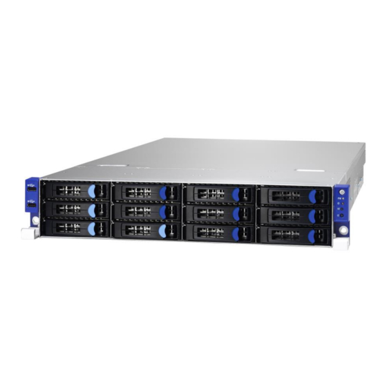
IT demand but also offers a smooth path for future application usage. ® TYAN also offers the TN70E-B8026 in a version that can support up to twelve hot-swap 2.5”/3.5” SATA HDD/SSD or NVMe SSD and two hot-swap 2.5”... -
Page 16: Features
(8) SATA 6Gb/s + (4) NVMe External Drive Bay Interface The SAS/SATA HDD backplane is connected to onboard SATA connection by default. Please Notification contact Tyan technical support if a discrete SAS HBA/RAID adapter installed is required. System Cooling (8) 6cm fans Configuration Type... - Page 17 PCI-E Gen3 x8 slots (right) (1) PCI-E Gen3 x16 OCP 2.0 slot (conn.A+conn.B), Others *Without using OCP 2.0 Mezz. card, please contact with Tyan technical support for details. (2) GbE ports, (1) GbE dedicated for Q'ty / Port IPMI Controller...
- Page 18 PCI-E & SATA interface) 2 onboard M.2 connectors shall support NVMe only when AMD EPYC™ 7002 Series Processors Notification deployed in all configurations. Please contact Tyan Technical Support for more details. Connector type D-Sub 15-pin Graphic Resolution Up to 1920x1200...
- Page 19 RoHS 6/6 Compliant Barebone (1) TN70E-B8026 Barebone Package Contains Manual (1) Quick Installation Guide Installation CD (1) TYAN Device Driver CD NOTE: 1. The specifications are subject to change without prior notice. 2. Please visit our website for the latest specifications. http://www.tyan.com...
-
Page 20: Standard Parts List
Standard Parts List This section describes TN70E-B8026 package contents and accessories. Open the box carefully and ensure that all components are present and undamaged. The product should arrive with packaged as illustrated below. 1.4.1 Box Contents If any items are missing or appear damaged, contact your retailer or browse to TYAN’s website for service:... -
Page 21: About The Product
The following views show you the product. 1.5.1 System Front View M1701T70-FPB Front Panel Board Power Button with green LED ID Button IPMI LED USB 2.0 Port ID LED USB 2.0 Port RESET Button 3.5” /2.5” SSD/ HDD bays http://www.tyan.com... - Page 22 Chassis Locate LED ID LED key.* System not identified HDD LED Color State Description NVME/SATA/SAS HDD fail HDD fail LED No failure found NVME/SATA/SAS HDD ready Green HDD Power/ Blinking NVME/SATA/SAS HDD access acivity Access LED Power disconnected http://www.tyan.com...
-
Page 23: System Rear View
RJ45 LAN Port (LAN2) Expansion Slots ID Button The rear 2 SATA SSDs/HDDs (#8 & #9) are not available when AMD EPYC™ 7002 Series Processors deployed in all configurations. Please contact Tyan Technical Support for more details. ID LED State Color Description... - Page 24 The chart below illustrates the different LED states. 10/100/1000 Mbps LAN Link/Activity LED Scheme Left LED Right LED Link Green 10 Mbps Active Blinking Green Link Green Green 100 Mbps Active Blinking Green Green Link Green Amber 1000 Mbps Active Blinking Green Amber No Link http://www.tyan.com...
-
Page 25: System Top View
1.5.3 System Top View http://www.tyan.com... - Page 26 (8) System fans M1601T70E-D-PDB Power Distribution Board DELTA, DPS 770GB C 770W Power Supply (2) Hot-swap 2.5” SSD trays Riser Card Bracket (M7106-L24-3F, M7106-R24-3F pre-installed) Memory Slots CPU Sockets PCIE3.0 SLOT x24 OCP A Slot (OCP1_A) OCP B Slot (OCP1_B) http://www.tyan.com...
-
Page 27: Chapter 2: Setting Up
Caution! To avoid damaging the motherboard and associated components, use torque force within the range kgf/cm (6.09 lb/in) on each mounting screw for motherboard installation. Do not apply power to the board if it has been damaged. http://www.tyan.com... -
Page 28: Precautions
Working on a system that is connected to a power supply can be extremely dangerous. Follow the guidelines below to avoid damage to TN70E-B8026 or injury to yourself. Ground yourself properly before removing the top cover of the system. -
Page 29: Installing Motherboard Components
CPUs, memory modules and add on cards. 2.1.1 Removing the Chassis Cover Follow these instructions to remove TN70E-B8026 chassis cover. 1. Remove the screw on the left side, and unscrew the rear top cover on the back side. Slide to lift the rear top cover up. -
Page 30: Removing The Air Duct
2.1.2 Removing the Air Duct 1. Remove the air duct from the chassis. http://www.tyan.com... -
Page 31: Installing The Cpu And Heatsink
Note: The force frame will automatically eject after the captive screws are being released. By placing your both index fingers on the sides on the metal handle, pull to release the rail frame. Then lift the rail frame to its fully open position. Remove the external cap from the rail frame. http://www.tyan.com... - Page 32 During installation, observe the following: 1. Make sure to push the carrier frame with package towards the end of the rail frame until it clicks into place. 2. Do not drop the carrier frame or touch the package pad to avoid component damage. http://www.tyan.com...
- Page 33 7. Close the force frame. Then use a T20 Torx screwdriver to tighten the screws to secure the force frame in a sequential order (1 ->2->3). 8. To secure the heatsink, use a T30 Security Torx to tighten the screws. Tighten the four screws in a diagonal sequence to secure the heat sink. http://www.tyan.com...
-
Page 34: Installing The Pci-E Card
2.1.4 Installing the PCI-E Card Follow these instructions to install the PCI-E card. 1. Unscrew the riser card bracket. 2. Remove the riser card bracket from the chassis. http://www.tyan.com... - Page 35 3. Unscrew to remove the dummy brackets. 4. Insert the PCI-E card into the riser card bracket and screw it firmly. Follow the same procedures to insert the card to the other side of the riser card bracket if necessary. http://www.tyan.com...
- Page 36 5. The same procedure to install the PCIE card to the second riser card. 6. Reposition and screw the riser card bracket into the chassis. http://www.tyan.com...
-
Page 37: Installing The Memory
2. Align the memory module with the slot. When inserted properly, the memory slot locking levers lock automatically onto the indentations at the ends of the module. Follow the recommended memory population table to install the other memory modules. http://www.tyan.com... - Page 38 Memory Population table http://www.tyan.com...
-
Page 39: Installing Hard Drives
2.1.6 Installing Hard Drives The TN70E-B8026 supports twelve 3.5”/2.5” hot-swap HDD/SSDs and two 2.5” hot-swap SSDs. Installing 3.5” Hot-Swap Hard Drives Follow these instructions to install a 3.5” HDD. Warning!!! Always install the hard disk drive to the chassis after the chassis has been secured on the rack. - Page 40 Place the 3.5” hard disk drive into the HDD tray and secure the HDD to the HDD tray using 4 screws. Reinsert the HDD tray into the chassis. Push to secure the locking lever until it clicks into place. http://www.tyan.com...
- Page 41 Follow these instructions to install a 2.5” HDD/SSD. Warning!!! Always install the hard disk drive to the chassis after the chassis has been secured on the rack. Press the locking lever latch and pull the locking lever open. Slide the HDD tray out. http://www.tyan.com...
- Page 42 Place the 2.5” HDD/SSD into the HDD tray and align the 2.5” HDD/SSD with its guide pins. Turn over the HDD tray and secure the HDD/SSD to the tray using 4 screws. http://www.tyan.com...
- Page 43 Reinsert the HDD tray into the chassis. Push to secure the locking lever until it clicks into place. http://www.tyan.com...
- Page 44 Always install the hard disk drive to the chassis after the chassis has been secured on the rack. Press the locking lever latch and pull the locking lever open. Remove the 4 screws to detach HDD tray bracket. Secure one side HDD screws. http://www.tyan.com...
- Page 45 Secure the other side HDD screws. Reinsert the HDD tray into the chassis. Push to secure the locking lever until it clicks into place. http://www.tyan.com...
-
Page 46: Rack Mounting
19" rack. NOTE: Before mounting the TYAN TN70E-B8026 in a rack, ensure that all internal components have been installed and that the unit has been fully tested. However, to make the installation easier, we suggest that you remove all HDD trays before you insert the chassis into the rack. - Page 47 Draw out the inner rail from the rail assembly. When the rail comes to a stop pull the tab to release the latch and completely draw the inner rail out. Align the inner sliding rail on the side of the server, and pull towards the arrow to secure the hooks http://www.tyan.com...
- Page 48 Repeat steps 2 to 4 to secure the sliding rail to the other side of the server. Installing the Outer Rails to the Unit Secure the outer rails to the rack using four M5 screws and four washers (A) on each side. Rack Mounting the Server Draw out the middle rail to the latch position. http://www.tyan.com...
- Page 49 When the inner rails come to a stop, pull the tab to release the latch and push the whole system in. Secure the mounting ears of the unit to the rack using two M5 x 20L screws (C). http://www.tyan.com...
- Page 50 NOTE http://www.tyan.com...
-
Page 51: Chapter 3: Replacing Pre-Installed Components
This chapter explains how to replace the pre-installed components, including the Motherboard, M1701T70-FP Front Panel Board, M1702T70-USB Board, M1290T70E-BP12E-12-1 HDD Backplane, M1287G88-BP12-2 HDD Backplane, Power Distribution board, M1601T70-D-PDB M7106-L24-3F M7106-R24-3F Riser cards, System fan and Power supply unit etc. Disassembly Flowchart The following flowchart outlines the disassembly procedure. http://www.tyan.com... -
Page 52: Removing The Cover
Removing the Cover Before replacing any parts you must remove the chassis cover first. Follow Chapter 2.1.1 to remove the cover of the TN70E-B8026. Replacing Motherboard Components Follow these instructions to replace motherboard components, including the motherboard. 3.4.1 Replacing the Riser Card... - Page 53 Unscrew the M7016-L24-3F riser card to replace with a new one. Unscrew the M7016-R24-3F riser card to replace with a new one. Follow the steps described earlier in reverse to reinstall the riser card bracket. http://www.tyan.com...
-
Page 54: Pci-E Riser Cards Specification
3.4.2 PCI-E Riser Cards Specification M7106-L24-3F Riser Card 3.4.3 Connector Pin Definition (M7106-L24-3F) Location Definition PCIe X16 SLOT 4P Power Connector PCIe X8 SLOT PCIe X8 SLOT http://www.tyan.com... -
Page 55: Connector Pin Definition (M7106-R24-3F)
M7106-R24-3F Riser Card 3.4.4 Connector Pin Definition (M7106-R24-3F) Location Definition PCIe X8 SLOT 4Pin Power Connector PCIe X16 SLOT PCIe X8 SLOT Signal Signal J2 (PWR1) +12V http://www.tyan.com... -
Page 56: Replacing The Front Panel Board
Replacing the Front Panel Board Follow these instructions to replace the M1701T70-FP Front Panel Board. 1 Unscrew to release the Front Panel Board cover. 2 Remove the Front Panel Board cover. http://www.tyan.com... - Page 57 3 Unscrew the Front Panel Board to replace a new one. 4 Disconnect the Front Panel Board to replace a new one. 5 Follow the steps described earlier in reverse to reinstall the Front Panel Board. http://www.tyan.com...
-
Page 58: Front Panel Board Specifications
Power On/Off LED Color: Green (after power on) ID LED Color: Blue LEDs Warning (IPMI) LED Dual Color: Amber (Warning) / Green (Normal) RESET button Push buttons ID button Power On/Off button with Power On/Off LED http://www.tyan.com... -
Page 59: Fpb Led And Connector Pin Definition
Chassis ID LED Locate LED key.* System not identified J1: FPIO connector Definition Definition PW_LED+ +5VSB ID_LED+ PW_LED- ID_LED- HD_LED+ LED_FAULT1- HD_LED- LED_FAULT2- PWR_SW+ LAN_ACT PWR_SW- LAN_LINK# RESET+ SMB_DAT RESET- SMB_CLK ID_SW- Temp_sensor SMB_ALR FPB_HDD_ACTIVITY_G- SMB_CLK FPB_HDD_FAULT_R- SMB_DAT http://www.tyan.com... -
Page 60: Replacing The Usb Board
Replacing the USB Board Follow these instructions to replace the M1702T70-USB Board. 1 Unscrew to release the USB front cover. 2 Remove the USB front cover. http://www.tyan.com... - Page 61 3 Unscrew the USB Board. 4 Disconnect the USB Board to replace a new one. 5 Follow the steps described earlier in reverse to reinstall the USB Board. http://www.tyan.com...
-
Page 62: Usb Board Specifications
USB Board Connector Pin Definition J2: 2x5-pin Connector for FP Connector of Motherboard Definition Description Definition Description VCC_USB USB power VCC_USB USB power USB_P0_N Port1(J1) USB- USB_P1_N Port2(J3) USB- USB_P0_P Port1(J1) USB+ USB_P1_P Port2(J3) USB+ GND1 Ground GND2 Ground No connect http://www.tyan.com... -
Page 63: Replacing The System Fan
Replacing the System Fan Follow these instructions to replace the fan. Disconnect the power cable. Press the button to take out the fan from the chassis. http://www.tyan.com... - Page 64 Release the rubber screws from the fan. Loose the screws on both sides. Push the latch in the direction as the arrow shown to release the fan from the iron holder. http://www.tyan.com...
- Page 65 Remove the iron holder to replace a new fan. After replacing a new one, put the fan unit back into the cage. http://www.tyan.com...
-
Page 66: Replacing The Fan Backplane Board
Replacing the Fan Backplane Board Follow these instructions to replace the M1806G70-FB Fan Board in your system. 1. Disconnect all the fan power cable. Use a screw driver to unscrew the fan cage. http://www.tyan.com... - Page 67 And lift it up from the chassis. Release the 14 screws on the Fan Backplane Board to replace a new one. Follow the steps described in reverse order to reinstall the fan cage. http://www.tyan.com...
-
Page 68: Fan Bp Board Specifications
(2) 1x4pin R/A Power Connector (8) 2x2pin Fan Connectors Integrated I/O (1) 2x10pin Barebone Fan Connector (1) 2x2pin Connector for S7086 3.8.2 Fan BP Board LED Definitions FAN Status Green LED(Right) Red LED(Left) With Fan Without Fan http://www.tyan.com... -
Page 69: Connector Pin Definitions
3.8.3 Connector Pin Definitions Power Connector (PWR1/PWR2) Definition Definition +12V Barebone Fan Connector (J8) Definition Definition FANIN1 FANIN6 FANIN2 FANIN7 FANIN3 FANIN8 FANIN4 SIO_FANIN1 FANIN5 SIO_ FANIN2 MB_PWM2 MB_PWM1 SIO_ FANIN3 SMBUS_3V3_DATA SIO_ FANIN4 SMBUS_3V3_CLK VDD_3.3_AUX MB_PWM3 http://www.tyan.com... -
Page 70: Replacing The Hdd Backplane Board
Before detach the HDD backplane, please remove all the HDD trays with HDDs, otherwise the HDD backplane will be damage when strains at the disassembly. Disconnect all cables connected to the M1290T70E-BP12E-12-1 Backplane. Remove the fan cage. Unscrew the HDD BP Board. http://www.tyan.com... - Page 71 Lift up the HDD Backplane bracket. The HDD BP Board bracket is as shown below. Unscrew the backplane and replace with a new HDD backplane board. Follow the procedures described earlier to reinstall the HDD backplane board bracket into the chassis. http://www.tyan.com...
-
Page 72: Hdd Backplane Board Features
HDD Backplane Board Features Front View Rear View Form Factor Dimension: 422.4*29.8mm (2) OCU Link Connector Input (3) Mini SAS HD Connector Input Specifications Overview (4) SGPIO Header (12) SATA HDD or (8) SATA HDD + (4) NVMe Output http://www.tyan.com... -
Page 73: Connector Definition
SATA Connector HDD7 SATA Connector HDD8 SATA Connector HDD9 SATA Connector HDD10 SATA Connector HDD11 SATA Connector SATA0_3 Mini SAS HD Connector SATA4_7 Mini SAS HD Connector SATA8_11 Mini SAS HD Connector NVME01 OCULink Connector NVME23 OCULink Connector Power Connector http://www.tyan.com... -
Page 74: Replacing The Power Distribution Board
Board in your system. Disconnect all cables connected to the power distribution board. Unscrew to take off the power distribution board and replace with a new one. Insert the PDB into the chassis following the above procedures in reverse. http://www.tyan.com... -
Page 75: Replacing The Rear Hdd Backplane Board
3.11 Replacing the Rear HDD Backplane Board Follow the instructions to replace the M1287G88-BP12-2 HDD backplane Board Disconnect all cables and unscrew the power distribution board. http://www.tyan.com... -
Page 76: Hdd Backplane Features
(1) SGPIO Connector(J2) (2) 7-pin SATA connector (1) 4 Pin Power connector The rear 2 SATA SSDs/HDDs (SATA0 & SATA1) are not available when AMD EPYC™ 7002 Series Processors deployed in all configurations. Please contact Tyan Technical Support for more details. http://www.tyan.com... -
Page 77: Connector Definition
HDD0: HDD Connector Definition Definition SAS_TX0+ SAS_TX0- SAS_RXBN0 SAS_RXBP0 SAS0_PRESENT_L HD0_V5 VDD_5_RUN VDD_5_RUN HD0_PRS_L SAS0_LED HD0_V12HD VDD_5_RUN VDD_5_RUN GND1 GND2 HDD1: HDD Connector Definition Definition SAS_TX1+ SAS_TX1- SAS_RXBN1 SAS_RXBP1 SAS0_PRESENT_L HD1_V5 VDD_5_RUN VDD_5_RUN HD1_PRS_L SAS1_LED HD1_V12HD VDD_5_RUN VDD_5_RUN GND1 GND2 http://www.tyan.com... - Page 78 SAS_RXBP0 SATA1: SATA Connector Definition Definition SAS_TX1+ SAS_TX1- SAS_RXBN1 SAS_RXBP1 J1: JTAG Connector Definition Definition CPLD_JTAG_TCK CPLD_JTAG_TDO VDD_3P3_RUN CPLD_JTAG_TMS CPLD_JTAG_TDI J2: SGPIO Connector Definition Definition SMBUS_3V3_CLK SAS_SIO_DIN_A SMBUS_3V3_DATA SAS_SIO_DOUT_A SAS_SIO_END_A SAS_SIO_CLK_A VCC3_AUX PW1: Power Connector Definition Definition VDD_12_RUN VDD_5_RUN http://www.tyan.com...
-
Page 79: Replacing The Power Supply
Follow these instructions to replace the power supply module in your system. Press the latch to pull the power supply out. After replacing a new power supply, press and hold the latch to push the power supply back into the chassis. http://www.tyan.com... -
Page 80: Disconnecting All Motherboard Cables
3.13 Disconnecting All Motherboard Cables Disconnect all cables connected to the motherboard. http://www.tyan.com... -
Page 81: Removing The Motherboard
After removing all of the aforementioned cables, follow the instructions below to remove the motherboard from the chassis. Remove the air duct, processor and heatsink if installed. Remove nine screws securing the motherboard to the chassis. Carefully lift the motherboard from the chassis. http://www.tyan.com... - Page 82 NOTE http://www.tyan.com...
-
Page 83: Appendix I: Installing Io Plate For Ocp Card
Appendix I: Installing IO Plate for OCP Card Follow these instructions to install the IO Plate for OCP Card. Here shows how to install the IO Plate for the dual-port LAN card M7062-I599-2T. Unscrew the riser card bracket. Remove the riser card bracket from the chassis. http://www.tyan.com... - Page 84 4. Take out the IO plate for LAN card. Use a screwdriver to break the LAN port’s semi shearing. Break one semi-shearing if a single-port LAN card is installed. Break both for a dual-port LAN card. http://www.tyan.com...
- Page 85 5. Insert the IO Plate to the OCP card LAN port. 6. Screw the IO Plate to the chassis http://www.tyan.com...
- Page 86 7. Insert the LAN card into the OCP slot 8. Secure the LAN card to the chassis http://www.tyan.com...
-
Page 87: Appendix Ii: Cable Connection Tables
S8026 MB M1702T70-USB USB3_FPIO1 Power Supply Cables M1601T70-D-PDB Connect to S8026 MB PW1 (MB) PATX1 (MB1) PATX2 (MB2) J7 (PSMI) PSMI_HD1 Power Supply Cables M1601T70-D-PDB Connect to M1806G70-FB PW4(FAN BD1) PW5(FAN BD2) http://www.tyan.com... - Page 88 SATA HDD Cable M1287G88-BP12-2-1 S8026 MB Connect to Rear HDD BP SSATADOM1 SSATA0 SSATADOM2 SSATA1 SGPIO Cable M1290T70E-BP12E-12-1 HDD S8026 MB Connect to SGPIO0 SGPIO0 SGPIO1 SGPIO2 Control Internal cable S8026 MB Connect to Chassis J122 Chassis http://www.tyan.com...
-
Page 89: Appendix Iii: Fan And Temp Sensors
The red dot indicates the sensor. Fan and Temp Sensor Location: Fan Sensor: It is located in the third pin of the fan connector, which detects the fan speed (rpm) Temp Sensor: SYS_Air_Outlet ,and MB_Air_Inlet etc. They detect the system temperature around. http://www.tyan.com... - Page 90 NOTE: The system temperature is measured in a scale defined by AMD, not in Fahrenheit or Celsius. BIOS Temp Sensor Name Explanation: http://www.tyan.com...
- Page 91 The highest temperature of CPU0 D2 UMC1 channel G slot P0_D2_UMC0_CH_H The highest temperature of CPU0 D2 UMC0 channel H slot BIOS FAN Sensor Name Explanation CPU0_FAN Fan speed of CPU0_FAN SYS_FAN_1 Fan speed of SYS_FAN_1 SYS_FAN_2 Fan speed of SYS_FAN_2 http://www.tyan.com...
- Page 92 Fan speed of SYS_FAN_5 SYS_FAN_6 Fan speed of SYS_FAN_6 SYS_FAN_7 Fan speed of SYS_FAN_7 SYS_FAN_8 Fan speed of SYS_FAN_8 SYS_FAN_9 Fan speed of SYS_FAN_9 SYS_FAN_10 Fan speed of SYS_FAN_10 SYS_FAN_11 Fan speed of SYS_FAN_11 SYS_FAN_12 Fan speed of SYS_FAN_12 http://www.tyan.com...
-
Page 93: Appendix Iv: Fru Parts Table
Appendix IV: FRU Parts Table TN70E-B8026 FRU Parts Item Model Number Part Number Picture Description TF-POWER SUPPLY;SBU,770 Power FRU-PS-0100 471100000247 W,DELTA,DPS-770GB C,(S0F),1U Supply MODULE,REV.S0F TF-FAN;SBU,12V,PFC0612DE-7N51,2BALL FRU-TS-0080 5412T4240001 ,1.68A,12000RPM,61.5dBA,60*60*38M M,4PIN TF-HEATSINK;SBU,AL/CU,SOLDERLING+PI PE,SP3-PASSIVE-1U-HEATSINK,SF4A9100 Heatsink FRU-TH-0260 343T58100002 01-1,78.9X119.3X25.0MM, SCREW,TN70A-B8026 TF-PWA;SBU,TN70E-B7106,M7106-L24-3 FRU-C-0490 411T56400041 F,R02,For BB,TYAN... - Page 94 CABLE,2*4P(M),P4.2/2*4P(M),P4.2+2*4P (M),P4.2,TN70-B7016 TF-AC/DC POWER CABLE;SBU,24 AWG,350MM,S4P PWR FRU-CS-0900 422T56700003 CABLE,1*4P(M),P2.54/1*4P(M),P2.54,GA 88-B5631 TF-AIRDUCT;SBU,PC+ABS, Air Duct FRU-TA-0070 344T57100002 TN70A-B8026 I/O PLATE TF-I/O PLATE LAN KIT;SBU,SGCC+SCREW FRU-SO-0160 452T57200005 LAN KIT +GASKET,GT62F-B5630 I/O PLATE TF-I/O PLATE SFP KIT;SBU, FRU-SO-0150 452T57200006 SGCC+SCREW,GT62F-B5630 SFP KIT http://www.tyan.com...
-
Page 95: Appendix V: Technical Support
MITAC serves multiple market segments with the industry’s most competitive services to support them. TYAN's tech support is some of the most impressive we've seen, with great response time and exceptional organization in general.” — Anandtech.com Please feel free to contact us directly for this service at tech-support@tyan.com... - Page 96 Return Merchandise Authorization (RMA) number. The RMA number should be prominently displayed on the outside of the shipping carton and the package should be mailed prepaid. TYAN will pay to have the board shipped back to you. ® TN70E-B8026 Service Engineer’s Manual V1.0c...
Need help?
Do you have a question about the TN70E-B8026 and is the answer not in the manual?
Questions and answers