Table of Contents
Advertisement
Quick Links
Advertisement
Table of Contents

Related Manuals for TYAN TN76-BP016


Summary of Contents for TYAN TN76-BP016
- Page 1 TN76-BP016 Service Engineer’s Manual http://www.tyan.com...
- Page 2 http://www.tyan.com...
- Page 3 MiTAC assumes no liability whatsoever, and ® disclaims any express or implied warranty, relating to sale and/or use of TYAN products including liability or warranties relating to fitness for a particular purpose or merchantability. MiTAC retains the right to make changes to produce descriptions and/or specifications at any time, without notice.
- Page 4 There will be danger of explosion if battery is incorrectly replaced. Replace only with the same or equivalent type recommended by manufacturer. Dispose of used battery according to manufacturer instructions and in accordance with your local regulations. この装置は、クラスA情報技術装置です。この装置を家庭環境で使用すると電波妨 害を引き起こすことがあります。この場合には使用者が適切な対策を講ずるよう要 求されることがあります。 VCCI-A http://www.tyan.com...
-
Page 5: About This Manual
How this guide is organized This guide contains the following parts: Chapter 1: Overview This chapter provides an introduction to the TYAN TN76-BP016 barebones and standard parts list, describes the external components, gives an overview of the product from different angles. -
Page 6: Safety And Compliance Information
Safety and Compliance Information Before installing and using TYAN TN76-BP016, take note of the following precautions: ·Read all instructions carefully. ·Do not place the unit on an unstable surface, cart, or stand. ·Do not block the slots and opening on the unit, which are provided for ventilation. -
Page 7: Safety Information
You must become familiar with the safety information in this guide before you install, operate, or service TYAN products. Symbols on Equipment Caution. This symbol indicates a potential hazard. -
Page 8: General Precautions
· Do not attempt to move a fully loaded rack. Remove equipment from the rack before moving it. · Do not attempt to move a rack on an incline that is greater than 10 degrees from the horizontal. http://www.tyan.com... - Page 9 This will reduce the risk of personal injury, fire, or damage to the equipment. The total rack load should not exceed 80 percent of the branch circuit rating. Consult the electrical authority having jurisdiction over your facility wiring and installation requirements. http://www.tyan.com...
- Page 10 TYAN, your authorized TYAN partner, or their agents. Equipment Modifications · Do not make mechanical modifications to the system. TYAN is not responsible for the regulatory compliance of TYAN equipment that has been modified.
- Page 11 – Liquid has been spilled on the product or an object has fallen into the product. – The product has been exposed to rain or water. – The product has been dropped or damaged. – The product does not operate normally when you follow the operating instructions. http://www.tyan.com...
-
Page 12: Table Of Contents
Table of Contents Chapter 1: Overview ................ 14 About the TYAN TN76-BP016 ..........14 Product Models ............... 14 Features.................. 15 Standard Parts List ..............24 1.4.1 Box Contents ..............24 1.4.2 Accessories ..............24 About the Product ..............25 1.5.1 System Front View ............ - Page 13 Petitboot System Configuration ..........94 Petitboot Config Retrieval ............96 Petitboot Shell ................ 97 Chapter 6: Diagnostics ..............99 Flash Utility ................99 Hostboot IPLs Progress Code ..........100 Appendix I: Cable Connection Tables ......... 105 Appendix II: Technical Support ............ 108 http://www.tyan.com...
-
Page 14: Chapter 1: Overview
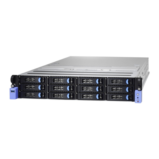
® TYAN also offers the TN76-BP016 in a version that can support up to twelve 3.5”/2.5’ fixed hard drives. The TN76-BP016 uses TYAN’s latest chassis featuring a robust structure and a solid mechanical enclosure. All of this provides TN76-BP016 the power and flexibility to meet the needs of nowadays server application. -
Page 15: Features
Features TYAN TN76-BP016 (BP016T76V12HR-LE) Form Factor 2U Rackmount Chassis Model TN76 System Dimension (D x W x H) 29.9" x 17.2" x 3.4" (760 x 438 x 87.6mm) Motherboard SP016GM2N Buttons (1) PWR w/ LED / (1) UID Front Panel... - Page 16 - 40° C ~ 70° C (-40° F ~ 158° F) Environment In/Non-operating 90%, non-condensing at 35° C Humidity RoHS RoHS 6/6 Compliant (1) TN76-BP016 Barebone w/MP016-9235-12I Barebone SATA 6G Mezz Card Package Contains (1) Web User's manual / (1) Quick Installation Manual...
- Page 17 (1) USB 3.0 port Type / Q'ty 3.5"/2.5"Hot-Swap / (12) HDD backplane External Drive SAS 12Gb/s/ SATA 6Gb/s support Pre-install TYAN P3260-9235-12I (3x 4-in-1 Mini-SAS HD; SATA Storage Mezzanine 6Gb/s IOC w/o RAID stack) System Cooling (11+1) 6cm fans Configuration...
- Page 18 - 40° C ~ 70° C (-40° F ~ 158° F) Environment In/Non-operating 90%, non-condensing at 35° C Humidity RoHS RoHS 6/6 Compliant (1) TN76-BP016 Barebone w/MP016-9235-12I Barebone SATA 6G Mezz Card Package Contains (1) Web User's manual / (1) Quick Installation Manual...
- Page 19 I/O Ports (1) USB 3.0 port Type / Q'ty 3.5"/2.5” Hot-Swap / (4) HDD backplane External Drive SAS 12Gb/s/ SATA 6Gb/s support Pre-install TYAN MP012-9235-4I (4-port SATA 6Gb/s IOC w/o Storage Mezzanine RAID stack) System Cooling (11+1) 6cm fans Configuration Type...
- Page 20 - 40° C ~ 70° C (-40° F ~ 158° F) Environment In/Non-operating 90%, non-condensing at 35° C Humidity RoHS RoHS 6/6 Compliant (1) TN76-BP016 Barebone w/MP012-9235-4I Barebone SATA 6G Mezz Card Package Contains (1) Web User's manual / (1) Quick Installation Manual...
- Page 21 3.5"/2.5” Hot-Swap / (12) / *Need a discrete Type / Q'ty HBA/RAID adapter to enable all drives. External Drive HDD backplane SAS 12Gb/s/ SATA 6Gb/s support Pre-install TYAN MP012-9235-4I (4-port SATA 6Gb/s IOC w/o Storage Mezzanine RAID stack) System Cooling (11+1) 6cm fans Configuration...
- Page 22 - 40° C ~ 70° C (-40° F ~ 158° F) Environment In/Non-operating 90%, non-condensing at 35° C Humidity RoHS RoHS 6/6 Compliant (1) TN76-BP016 Barebone w/MP012-9235-4I Barebone SATA 6G Mezz Card Package Contains (1) Web User's manual / (1) Quick Installation Manual Guide http://www.tyan.com...
- Page 23 L10 system configuration table (for Channel) Model TN76-BP016 BP016T76V4HR BP016T76V12HR BP016T76V12HR BP016T76V12HR SP016GM2N SP016GM2N SP016GM2N SP016GM2N MP016T76-MEB MP016T76-MEB Not include Not include (only in FRU) (only in FRU) Riser#1 MP016T76-L16-1F MP016T76-L16-2F MP016T76-L16-2F MP016T76-L16-2F Riser#2 MP016T76-R16-1F MP016T76-R16-2F MP016T76-R16-2F MP016T76-R16-2F Not include...
-
Page 24: Standard Parts List
If any items are missing or appear damaged, contact your retailer or browse to TYAN’s website for service: http://www.tyan.com The web site also provides information of other TYAN products, as well as FAQs, compatibility lists, BIOS settings, etc. Accessory Kit (2) US Power Cord ... -
Page 25: About The Product
HDD/SSD5 HDD/SSD8 HDD/SSD11 HDD/SSD1 HDD/SSD4 HDD/SSD7 HDD/SSD10 HDD/SSD0 HDD/SSD3 HDD/SSD6 HDD/SSD9 Description USB3.0 Port Front Panel Board Power On/Off Button with green LED ID Button ID LED (blue color) FAULT LED (amber color) (12) 3.5”/2.5” SAS/SATA 6G/12G hot-swap HDDs/SSDs http://www.tyan.com... - Page 26 TN76-BP016-HE HDD/SSD Sequence HDD/SSD2 HDD/SSD1 HDD/SSD0 HDD/SSD3 Description USB3.0 Port Front Panel Board Power On/Off Button with green LED ID Button ID LED (blue color) FAULT LED (amber color) (4) 3.5”/2.5” SAS/SATA 6G/12G hot-swap HDDs/SSDs http://www.tyan.com...
- Page 27 Activity LED (Green color) Status LED (Orange color) Drive State Drive Present, No Activity Solid On Drive Present, with Activity Blinking Drive Fail Don’t care Solid On Drive identify Don’t care Blinking @ 1Hz Drive Rebuild Don’t care Blinking @ 4Hz http://www.tyan.com...
-
Page 28: System Rear View
2 x USB 3.0 Ports RJ-45 Connector (LAN1) RJ-45 Connector (LAN2) USB 3.0 single port ID-LED 1 x HH-FL PCIE Slot SFP4+SFP3+ SFP2+ SFP1 (interface from mezzanine card) ID_LED SW VGA Port Serial Port 2 x HH-FL PCIE+GPU Card Slot hex wrench http://www.tyan.com... -
Page 29: System Top View
System Top View BP016T76V4HR-HE Description (4) 3.5”/2.5” 6G/12G SAS/SATA hot-swap HDDs/SSDs HDD Backplane Board (6) System Fans MP016T76-MEB Memory Expansion Board CPU Air Duct GPU Card brackets (1+1) 1000W(@110Vac) /1600W(@220Vac) Power Supply (underneath) NOTE: The system is pre-installed with SP016 mainboard. http://www.tyan.com... - Page 30 BP016T76V12HR-LE & BP016T76V12HR-SL Description (12) 3.5”/2.5” 6G/12G SAS/SATA hot-swap HDDs/SSDs HDD Backplane Board (6) System Fans CPU Air Duct GPU Card brackets (1+1) 1000W(@110Vac) /1600W(@220Vac) Power Supply (underneath) NOTE: The system is pre-installed with SP016 mainboard. http://www.tyan.com...
- Page 31 BP016T76V12HR Description (12) 3.5”/2.5” 6G/12G SAS/SATA hot-swap HDDs/SSDs HDD Backplane Board (6) System Fans MP016T76-MEB Memory Expansion Board CPU Air Duct GPU Card brackets (1+1) 1000W(@110Vac) /1600W(@220Vac) Power Supply (underneath) NOTE: The system is pre-installed with SP016 mainboard. http://www.tyan.com...
-
Page 32: Chapter 2: Setting Up
Caution! To avoid damaging the motherboard and associated components, do not use torque force greater than 7kgf/cm (6.09 lb/in) on each mounting screw for motherboard installation. Do not apply power to the board if it has been damaged. http://www.tyan.com... -
Page 33: Precautions
Working on a system that is connected to a power supply can be extremely dangerous. Follow the guidelines below to avoid damage to TN76-BP016 or injury to yourself. Ground yourself properly before removing the top cover of the system. -
Page 34: Installing Motherboard Components
CPU, heatsink, air duct, memory modules, HDD/SSD and LAN Card. 2.1.1 Removing the Chassis Cover Follow these instructions to remove the TN76-BP016 chassis cover. Unscrew the top cover. Slide the top cover off. Remove the top cover from the chassis. -
Page 35: Installing The Cpu, Heatsink
Follow the steps below on installing the process, heatsink and air duct. Unclip to take out the hex wrench. Take out the protection cap. Place the CPU into the socket and make sure that the gold arrow is located in the right direction. http://www.tyan.com... - Page 36 DO NOT apply any thermal grease/pad other than the one shipped with heatsink onto the CPU. Pull the clips to place the heatsink on top of the CPU. Use the hex wrench to secure the heatsink to the chassis. http://www.tyan.com...
-
Page 37: Installing The Memory
Align the memory module with the slot. When inserted properly, the memory slot locking levers lock automatically onto the indentations at the ends of the module. Follow the recommended memory population table to install the other memory modules. http://www.tyan.com... - Page 38 DIMM Population Table DIMM Plug Rules http://www.tyan.com...
-
Page 39: Installing The Lan Mezz Card
2.1.4 Installing the LAN Mezz Card Follow these instructions to install the LAN Mezz Card. Locate the four screw holes for the LAN Mezz Card Place the LAN Mezz card onto the holes and secure it with four screws. http://www.tyan.com... -
Page 40: Installing Hard Drives
Follow these instructions to install (12) 3.5”/2.5” hard drives. Warning!!! Always install the hard disk drive to the chassis after the chassis is secured on the rack. HDD Trays Push the latch to pull the hard disk tray out. http://www.tyan.com... - Page 41 Place a 3.5" hard drive into the HDD tray and secure the HDD with 4 HDD screws. (Option 2: 2.5” HDD/SSD) Place a 2.5” hard drive into the HDD tray. Turn the HDD tray over and secure the HDD/SSD with 4 screws. http://www.tyan.com...
- Page 42 Reinsert the HDD tray into the chassis. http://www.tyan.com...
-
Page 43: Rack Mounting
2.2.1 Installing the Server in a Rack Follow these instructions to mount the TYAN TN76-BP016 into an industry standard 19" rack. NOTE: Before mounting the TYAN TN76-BP016 in a rack, ensure that all internal components have been installed and that the unit has been fully tested. -
Page 44: Installing The Inner Rails To The Chassis
Installing the inner Rails to the Chassis Release and detach the inner rail from the sliding rail. Align the inner sliding rail on one side of the server. Pull the inner sliding rail forward to secure it to the chassis. http://www.tyan.com... - Page 45 Screw the inner rail to the chassis. Align and screw the inner sliding rail on the other side of the server. http://www.tyan.com...
-
Page 46: Installing The Outer Rails To The Rack
2.2.3 Installing the Outer Rails to the Rack Secure the outer rails to the rack. Screw the outer rails to the rack. http://www.tyan.com... -
Page 47: Rack Mounting The Server
2.2.4 Rack mounting the Server Lift the unit and then insert the inner slide rails into the middle rails. Push the whole system into the rack. Secure the whole system to the rack with 2 thumb screws. http://www.tyan.com... -
Page 48: Chapter 3: Replacing Pre-Installed Components
This chapter explains how to replace the pre-installed components, including the SP016 Motherboard, M1271T71-BP12-12 12-Ports 6G/12G HDD Backplane Board, M1715T71-FPB Front Panel Board, MP016T76 Fan Board, MP012-9235-4I Storage Mezz Card, System Fan and Power Supply Unit etc. 3.0.2 Disassembly Flowchart The following flowchart outlines the disassembly procedures. http://www.tyan.com... -
Page 49: Removing The Cover
Removing the Cover Before replacing any parts you must remove the chassis cover. Follow Section 2.1.1 Removing the Chassis Cover (page 34) to remove the cover of the TN76-BP016. Replacing Motherboard Components Follow these instructions to replace motherboard components, including the motherboard. -
Page 50: Removing The Motherboard
FRU and follow the instruction stated in Section 2.1.2 Installing the CPU, Heatsink (page 35). Remove the 13 screws securing the motherboard to the chassis. Carefully lift the motherboard from the chassis. http://www.tyan.com... -
Page 51: Replacing The Storage Mezz Card
MP012-9235-4I Storage Mezz Card. Unscrew the Storage Mezz Card and disconnect the cable connected to the card. Lift the card to replace with a new one. Follow the procedures in reverse order to reinstall a new Storage Mezz Card. http://www.tyan.com... -
Page 52: Replacing The Mp016T76-Meb Memory Expansion Board
Replacing the MP016T76-MEB Memory Expansion Board Follow these instructions to replace the MP016T76-MEB Memory expansion Board. Remove the 13 Memory expansion board screws. Release the Memory expansion board chassis as illustrated the direction of arrow. Lift the chassis up. http://www.tyan.com... -
Page 53: Mp016T76-Meb Memory Expansion Board Features
3.4.1 MP016T76-MEB Memory Expansion Board Features http://www.tyan.com... -
Page 54: Replacing The Hdd Backplane Board
Replacing the HDD Backplane Board Follow these instructions to replace the M1271T71-BP12-12 12-Ports HDD Backplane Board. Pull all front HDD trays out. Disconnect the power cable. Disconnect the 3pcs Mini-SAS HD cable. http://www.tyan.com... - Page 55 Unscrew the HDD BP bracket. Loose the screws on both sides of the chassis. Take out the HDD BP board. http://www.tyan.com...
- Page 56 Release 8 push pins to lift the mylar. Loose ten screws to replace with a new HDD BP Board. Reinstall the HDD BP Board into the chassis following the steps in reverse. http://www.tyan.com...
-
Page 57: Hdd Bp Board Features
(3) Mini-SAS HD Connector connected to MB Specifications (MINI_SAS0~2) (1) 12-pin Power Connector connected to MB (PW5) (1) 30-pin Fan Connector connected to MB (J36) (5) 6-pin Fan Connector connected to Fan (FAN1~5) (12) HDD/SSD Active LEDs LEDs (12) HDD/SSD Fault LEDs http://www.tyan.com... -
Page 58: Connector Pin Definitions
VDD_12_RUN VDD_12_RUN J36: 30-pin FAN Connector Definition Definition FAN_TACH1 FAN_TACH6 FAN_TACH2 FAN_TACH7 FAN_TACH3 FAN_TACH8 FAN_TACH4 FAN_TACH9 FAN_TACH5 FAN_TACH10 CON_PWM2 CON_PWM1 FAN_TACH11 FAN_TACH12 CON_PWM3 FAN_TACH13 FAN_TACH15 FAN_TACH14 FAN_TACH16 CON_PWM4 CON_PWM6 FAN1~FAN5: 6-pin FAN Connector Definition Definition VDD_12_FAN1 CON_PWM1 FAN_TACH1 VDD_12_FAN1 http://www.tyan.com... -
Page 59: Replacing The Front Panel Board
Front Panel Board. Unscrew the front panel bezel. Take out the front panel bezel and unscrew the Front Panel Board. Disconnect the Front Panel control cable. Reinstall the Front Panel Board into the chassis following the steps in reverse. http://www.tyan.com... -
Page 60: Front Panel Board Features
Specifications (1) ID Button (SW1) (1) blue color ID LED (LED_ID1) (1) orange color FAULT LED (LED_FAULT1) 3.6.2 Connector Pin Definitions J1: Front Panel Board Connector Definition Definition FP_PW_LED_PW FP_PWR_BTN_N VCC_FPB FP_ID_LED_PW FP_PW_LED_GND FP_ID_LED_N FP_SMB_DAT BMC_HW_FAULT_N FP_SMB_CLK FP_IDLED_BTN_N BMC_SYS_FAULT_N http://www.tyan.com... -
Page 61: Replacing The Usb Board
Replacing the USB Board Follow these instructions to replace the M1714T71-USB USB Board. Unscrew 4 screws to release the USB board bezel. Take out the USB Board bezel. Disconnect the Front USB3.0 Cable. http://www.tyan.com... - Page 62 Unscrew the USB Board bracket. Slide to take out the USB Board bracket. Unscrew the USB Board to replace with a new one. Reinstall the USB Board bracket into the chassis following the steps in reverse order. http://www.tyan.com...
-
Page 63: Replacing The Fans
Replacing the Fans Follow these instructions to replace the fans. 1. Take out the fan module from the chassis. 2. Replace the failed fan module with a new one. 3. Loose the screws on both sides. http://www.tyan.com... - Page 64 4. Push the latch in the direction as the arrow shown to release the fan from the iron holder. 5. Remove the iron holder to replace a new fan. Follow the procedure reverse order to reinstall the system fan. http://www.tyan.com...
-
Page 65: Replacing The Fan Board
Replacing the Fan Board Follow these instructions to replace the MP016T76-FB Fan Board. Take out the fan modules. Remove the six screws. Take out the fan chassis. http://www.tyan.com... - Page 66 Disconnect the fan cables. Remove the 8 screws. http://www.tyan.com...
-
Page 67: Fan Board Features
Rear view: Form Factor W389.5 x L54 (mm), 4-layer PCB (12) FAN Connector Specifications (2) Power Connector(J2/J5) (2)FAN Cable Connector(J1/J6) LEDs (12) Fan Fail LEDs 3.9.2 Fan Board LED Definition FAN Status Upper LED lower LED Normal On(Green) On(Green) Abnormal http://www.tyan.com... -
Page 68: Connector Pin Definitions
PIN 24 VCC3_AUX PIN 25 PIN 26 PIN 27 PIN 28 PWM_SYS4 PWM_SYS5 PIN 29 PIN 30 PWM_SYS6 FAN Connector (FAN1-FAN12) FAN1-FAN12 FAN Connector PIN 1 PIN 2 PIN 3 PIN 4 VDD_12V_RUN FAN_PWM TACH PIN 5 PIN 6 http://www.tyan.com... -
Page 69: Replacing The Power Supply
The system has two pre-installed Power Supply Units. Please unplug the power cord before you follow these instructions to replace the power supply units. Press the latch to pull the power supply out. After replacing a new power supply, press the latch to push the power supply back into the chassis. http://www.tyan.com... -
Page 70: Chapter 4: Mainboard Information
Caution! To avoid damaging the motherboard and associated components, do not use torque force greater than 7kgf/cm (6.09 lb/in) on each mounting screw for motherboard installation. Do not apply power to the board if it has been damaged. http://www.tyan.com... -
Page 71: Board Image
Board Image SP016 This picture is representative of the latest board revision available at the time of publishing. The board you receive may not look exactly like the above picture. http://www.tyan.com... -
Page 72: Block Diagram
Block Diagram SP016 Block Diagram http://www.tyan.com... -
Page 73: Mainboard Mechanical Drawing
Mainboard Mechanical Drawing http://www.tyan.com... -
Page 74: Board Parts, Jumpers And Connectors
The board you receive may not look exactly like the above diagram. The DIMM slot numbers shown above can be used as a reference when reviewing the DIMM population guidelines shown later in the manual. For the latest board revision, please visit our web site at http://www.tyan.com. http://www.tyan.com... - Page 75 1.RJ45 LAN Port #3 (LAN3)dedicate to IPMI + 18. SM Bus Connector (J18) USB 3.0 Ports( J26) 2. RJ45 LAN Port #1 (LAN1) + RJ45 LAN Port #2 19. TYAN Module Header (J47) (LAN2) (Dual LAN1) 3. USB 3.0 Port(J103) 20. USB 3.0 Connector(USB3_2) 4.
- Page 76 Use this header to connect the cooling fan to your motherboard to keep the system stable and reliable. SSI_FP1: Front Panel Connector Signal Signal PW_LED_P VCC3 ID_LED_P PW_LED_N ID_LED_N HDD_LED HW_FAULT- HDD_ACT_LED SYS_FAULT- PWR_BTN LAN1_ACT PHY_LED- RST_BTN SMB_DAT SMB_CLK IDLED_BTN INTRUDER- LAN2LED+ NMI_SW# INTRUSION1: Chassis Intrusion Header Signal Signal INTRUDER# http://www.tyan.com...
- Page 77 FAN PWM2 FAN PWM1 FAN TACH11 SMBDATA FAN TACH12 SMBCLK V3P3_AUX FAN PWM3 V3P3_AUX FAN TACH13 FAN TACH15 FAN TACH14 FAN TACH16 FAN PWM4 FAN PWM5 USB3_2: USB3.0 Connector Signal Signal VCC1 P0_RX_N VCC1 P0_RX_P P0_TX_N P0_TX_P P0_N P0_P OC_N http://www.tyan.com...
- Page 78 TYPEA_USB3: Vertical (Type_A) USB3.0 Connector Signal Signal USB2.0_DATA_N USB2.0_DATA_P USB3.0_RX_N USB3.0_RX_P USB3.0_TX_N USB3.0_TX_P IPMB1: IPMB Pin Header Signal BMC_SMB_DATA BMC_SMB_CLK J47: TPM(TYAN Module Header) Signal Signal INTERRUPT RESET SMBUS-DAT INTERRUPT2 SMBUS-CLK RESET2 RESERED J8: APSS JTAG Connector Signal Signal TRST...
- Page 79 J36: CPLD JTAG Header Signal Signal J9: VPD Connector Signal Signal I2C SDA I2C SCL J46: PSU SIGNAL Connector Signal Signal +12VSB +12VSB PS_ON ALERT PSU2_A0 PSU2_A1 SMART_ON RETURN 12VSL +12V PRESENT PWOK PS_KILL http://www.tyan.com...
- Page 80 TRST J14/J18/J41: SMBUS Connector Signal Signal SMB CLK SMB DATA J15: SMBUS Connector Signal Signal SMB CLK SMB DATA J42: PLX8718 SMBus Select Jumper Signal Signal BMC_PEX_DATA BMC_PEX_CLK SMB_DAT1_CN SMB_CLK1_CN DBG_SMB_DAT DBG_SMB_CLK 3PHD_8: CFAM_RESET_NConnector Signal Signal UCD-PGOOD CFAM_RESET_N BMC_CFAM_RESET_N http://www.tyan.com...
-
Page 81: Tips On Installing Motherboard In Chassis
Be especially careful to look for extra stand-offs. If there are any stand-offs present that are not aligned with a mounting hole on the motherboard, it will likely short components on the back of the motherboard when installed. This will cause malfunction and/or damage to your motherboard. http://www.tyan.com... - Page 82 Some chassis include plastic studs instead of metal. Although the plastic studs are usable, MiTAC recommends using metal studs with screws that will fasten the motherboard more securely in place. Below is a chart detailing what the most common motherboard studs look like and how they should be installed. http://www.tyan.com...
-
Page 83: Memory
8GB DR x8 with 4GB DRAM 16GB DR x4 with 4GB DRAM 32GB QR x4 with 4GB DRAM 32GB DIMMs in both slot0 and slot1 of any Centaur downstream of the processor socket forces DDR speed to 1066. DIMM Plug Rules http://www.tyan.com... - Page 84 DIMM Population Table http://www.tyan.com...
-
Page 85: Connecting External Devices
10/100/1000 Mbps LAN Link/Activity LED Scheme Left LED Right LED Link Green 10 Mbps Active Blinking Green Solid Green Link Green 100 Mbps Solid Green Active Blinking Green Solid Yellow Link Green 1000 Mbps Solid Yellow Active Blinking Green No Link http://www.tyan.com... -
Page 86: Installing The Power Supply
EPS 12V power supply. PWR1: 50-pin Power Connector Signal Signal +12V_IN +12V_IN +12V_IN +12V_IN +12V_IN +12V_IN +12V_IN +12V_IN +12V_IN +12V_IN +12V_IN +12V_IN +12V_IN +12V_IN +12V_IN +12V_IN +12V_IN +12V_IN PSU1_SDA PSU1_A0 PSU1_SCL PSU1_A1 PSU1_PSON_N +12VSB PSU1_ALERT PSU1SMART_ON PSU1_RETURN_S PSU1_12VLS PSU1_12VS+ PSU1_PRESENT_N PSU1_PWOK PSU1_PS_KILL http://www.tyan.com... - Page 87 +12V_IN +12V_IN +12V_IN +12V_IN +12V_IN +12V_IN PSU1_SDA PSU1_A0 PSU1_SCL PSU1_A1 PSU1_PSON_N +12VSB PSU1_ALERT PSU1SMART_ON PSU1_RETURN_S PSU1_12VLS PSU1_12VS+ PSU1_PRESENT_N PSU1_PWOK PSU1_PS_KILL J46: ATX 24-pin Power Connector Signal Signal +12V_IN +12V_IN +12V_IN +12V_IN +12V_IN +12V_IN +12V_IN +12V_IN +12V_IN +12V_IN +12V_IN +12V_IN http://www.tyan.com...
- Page 88 PWR5/PWR6/PWR7/PWR8: Power Connector for GPU Signal Signal +12V_GPU +12V_GPU +12V_GPU +12V_GPU PWR10: 4-pin Power Connector Signal Signal +12V NOTE: You must unplug the power supply before plugging the power cables to motherboard connectors. Apply 5Vsb power supply with current support below 2A. http://www.tyan.com...
-
Page 89: Chapter 5: Petitboot Bootloader
Function Left/Right Arrow Keys Move between characters Up/Down Arrow Keys Move between selections Enter Open highlighted section or accept the configuration Move to the next selection Tab + Shift Keys Move to the previous selection ESC/X Keys Exit http://www.tyan.com... -
Page 90: Getting Help
The following pages provide the details of Petitboot menu. Please be noticed that the Petitboot menu are continually changing due to the Processor NOR (PNOR) firmware updating. The Petitboot menu provided are the most updated ones when this manual is written. Please visit TYAN’s website at http://www.tyan.com for the information of PNOR firmware updating. -
Page 91: Petitboot Main Menu
(YYYY/MM/DD) on the left and the TYAN product name on the right. A help and status menu is displayed at the lower part of the Petitboot screen. Also, if Petitboot returns a list of boot options that are available to the system, you can select them by below methods: To select a boot option, press Enter. - Page 92 Find new or updated boot options on the system, select the 'Rescan devices' option. Retrieve config from URL Retrieve new boot options from a remote configuration file, select the 'Retrieve config from URL' option. Exit to shell Close the Petitboot interface, type X (exit). http://www.tyan.com...
-
Page 93: Petitboot System Information
This screen shows general information about the system type, ID, FW versions and including the MAC addresses of each network interface for use when configuring boot behaviors. Petitboot System Information ───────────────────────────────────── System type: TN76-BP016 System id: 0000000000000000 Network interfaces enP3p13s0f0 :... -
Page 94: Petitboot System Configuration
To select the 'Add Device' button , new devices can be added to the autoboot list, either by UUID, MAC address, or device type. Once added to the bootorder, the priority of devices can be changed with the 'left' and 'right' keysDevices can be http://www.tyan.com... -
Page 95: Network Options
Disk R/W: Prevent all writes to disk / Allow bootloader scripts to modify disks Certain bootloader configurations may request writes access to disk to save information or update parameters (eg. GRUB2). Use this option to control access to disks. http://www.tyan.com... -
Page 96: Petitboot Config Retrieval
[ OK ] [ Help ] [ Cancel ] ───────────────────────────────────── tab=next, shift+tab=previous, x=exit, h=help Configuration URL: Supply a valid URL here to retrieve a remote pxe-boot config file and parse it. URLs are of the form 'scheme://host/path/to/pxeconffile', such as tftp://host/pxeconffile or http://host/pxeconffile http://www.tyan.com... -
Page 97: Petitboot Shell
If user selects the 'Exit to Shell' menu item, system will exit the Petitboot program and present the user with a Linux shell prompt. This shell is a busybox based system that includes many of the standard shell commands and Linux utilities. Exiting petitboot. Type 'exit' to return. http://www.tyan.com... - Page 98 NOTE http://www.tyan.com...
-
Page 99: Chapter 6: Diagnostics
PNOR flash failure, you must contact your dealer for a replacement PNOR. There are no exceptions. TYAN does not have a policy for replacing PNOR chips directly with end users. In no event will TYAN be held responsible for damages done by the end user. -
Page 100: Hostboot Ipls Progress Code
Clean up MCS extent regs ISTEP 06.09 Setup centaur ref clocks ISTEP 06.10 Update SBE config data area ISTEP 06.11 Start the SBE engine on slave chips ISTEP 06.12 Check Slave SBE Complete ISTEP 06.13 vSBE Init of Slave Chips http://www.tyan.com... - Page 101 Cen TP Chiplet array init ISTEP 10.07 Cen TP Chiplet Start clocks ISTEP 10.08 Cen Chiplet Init ISTEP 10.09 Chiplet array init ISTEP 10.10 Cen DTS init ISTEP 10.11 Cen Scan overrides ISTEP 10.12 Manual Cen Scans ISTEP 10.13 Start Cen Nest http://www.tyan.com...
- Page 102 ISTEP 13.09 DRAM training ISTEP 13.10 Advanced DRAM training ISTEP 13.11 Hand off control to MC ISTEP 13.12 Pass in all DIMMs on a given power domain IStep 14 – DRAM Initialization ISTEP 14.01 Load PRD for DRAM domain http://www.tyan.com...
- Page 103 ISTEP 18.13 Create TOD topology ISTEP 18.14 Start TOD to running state IStep 21 - Start Payload ISTEP 21.01 Host runtime setup ISTEP 21.02 Host verify HDAT structures ISTEP 21.03 Start shutdown sequence of Hostboot and start the Payload http://www.tyan.com...
- Page 104 NOTE http://www.tyan.com...
-
Page 105: Appendix I: Cable Connection Tables
Connect to SP016 M/B → USB cable USB3_2 4. HDD PWR Cable M1271T71-BP12 to SP016 M/B M1271T71-BP12 Connect to SP016 M/B → PWR3 5. Mini-SAS HD Cable M1271T71-BP12 to P3260-9235-12I M1271T71-BP12 Connect to P3260-9235-12I → Mini_SAS0 → Mini_SAS1 → Mini_SAS2 http://www.tyan.com... - Page 106 6. GPU PWR Cable SP016 to GPU Card SP016 Connect to GPU Card → PWR7 GPU1 → PWR6 GPU2 http://www.tyan.com...
- Page 107 NOTE http://www.tyan.com...
-
Page 108: Appendix Ii: Technical Support
MiTAC serves multiple market segments with the industry’s most competitive services to support them. Please feel free to contact us directly for this service at tech-support@tyan.com Help Resources: 1. See the POST codes section of this manual. - Page 109 (RMA) number. The RMA number should be prominently displayed on the outside of the shipping carton and the package should be mailed prepaid. TYAN will pay to have the board shipped back to you. TYAN® TN76-BP016 Service Engineer’s Manual V1.0 Document No.: D2316-100 http://www.tyan.com...
Need help?
Do you have a question about the TN76-BP016 and is the answer not in the manual?
Questions and answers