Table of Contents
Advertisement
Quick Links
Advertisement
Table of Contents

Related Manuals for Patton electronics 3196RC


Summary of Contents for Patton electronics 3196RC
-
Page 1: User Manual
Model 3196RC iDSL TDM-Digital Access Concentrator (T-DAC) User Manual Sales Office: +1 (301) 975-1000 Technical Support: +1 (301) 975-1007 E-mail: support@patton.com WWW: www.patton.com Part Number: 07MD3196RC-GS, Rev. D Revised: February 17, 2012... - Page 2 Patton Electronics Company, Inc. 7622 Rickenbacker Drive Gaithersburg, MD 20879 USA Tel: +1 (301) 975-1000 Fax: +1 (301) 869-9293 Support: +1 (301) 975-1007 Web: www.patton.com E-mail: support@patton.com Copyright © 2012, Patton Electronics Company. All rights reserved. The information in this document is subject to change without notice. Patton Elec- tronics assumes no liability for errors that may appear in this document.
-
Page 3: Summary Table Of Contents
Summary Table of Contents Introduction ..............................16 Hardware installation............................ 24 Configuring the T-DAC for operation ......................35 Operation and shutdown..........................68 Troubleshooting and maintenance ........................ 70 Contacting Patton for assistance ........................85 Network Ports (RJ-21X) connector pin-out ....................88 WAN Network Module connector pinout .................... -
Page 4: Table Of Contents
Table of Contents Summary Table of Contents ........................... 3 Table of Contents ............................4 List of Figures ..............................7 List of Tables ..............................9 Compliance Information ..........................10 Radio and TV Interference ..........................10 Industry Canada Notice ..........................11 FCC Part 68 (ACTA) Statement ........................11 CE Notice ...............................12... - Page 5 Model 3196RC T-DAC User Manual Connecting the Ethernet ports ........................27 Connecting the 10/100Base-T Ethernet port to an Ethernet switch or hub ..........27 Connecting the 10/100Base-T Ethernet port to an Ethernet-capable workstation or PC ........28 Connecting the EIA-561 RS-232 configuration port (DCE configured) ............28 Connecting to the T1/E1 WAN ports ......................29...
- Page 6 Model 3196RC T-DAC User Manual Remote loop ..............................75 Line Loop ..............................76 T1/E1 port test modes ............................77 DSX1 payload loop (dsx1PayloadLoop) ....................77 DSX1 line loop (dsxLineLoop) ........................78 Periodic maintenance ............................78 Calibration ..............................78 Maintenance................................79 Replacing the Model 3196RC .........................79 Exporting the current Model 3196RC configuration ................79 Removing the defective Model 3196RC ....................82...
-
Page 7: List Of Figures
List of Figures Ferrite location ............... . . 10 Model 3196RC T-DAC . - Page 8 Model 3196RC T-DAC User Manual 3196RC Configuration Menu home page ........... . 63 IMPORT/EXPORT page .
-
Page 9: List Of Tables
List of Tables General conventions ..............14 Mouse conventions . -
Page 10: Compliance Information
Compliance Information Interference and TV Radio The Model 3196RC generates and uses radio frequency energy, and if not installed and used properly—that is, in strict accordance with the manufacturer's instructions—may cause interference to radio and television recep- tion. The Model 3196RC has been tested and found to comply with the limits for a Class A computing device in accordance with the specifications in Subpart B of Part 15 of FCC rules, which are designed to provide rea- sonable protection from such interference in a commercial installation. -
Page 11: Industry Canada Notice
Model 3196RC T-DAC User Manual Industry Canada Notice Note This equipment meets the applicable Industry Canada Terminal Equip- ment Technical Specifications. This is confirmed by the registration number. The abbreviation, IC, before the registration number signifies that registration was performed based on a Declaration of conformity indicating that Industry Canada technical specifications were met. -
Page 12: Ce Notice
Model 3196RC T-DAC User Manual pany for leased line facilities. The Universal Service Order Code (USOC) is RJ48. The Facility Interface Codes (FIC) are 04DU9-BN, 04DU9-DN, 04DU9-1KN, and 04DU9-1SN. The Service Order Code (SOC) is 6.0N. Facility Service Network Service Interface Code Code Connection... -
Page 13: About This Guide
About this guide This guide describes installing and configuring a Patton Electronics Model 3196RC TDM-Digital Access Concentrator (T-DAC). By the time you are finished with this guide, your T-DAC will be connected to the remote DSL modems and transferring data. The instructions in this guide are based on the following assump- tions: •... -
Page 14: Precautions
Model 3196RC T-DAC User Manual Precautions Notes and cautions, which have the following meanings, are used throughout this guide to help you become aware of potential T-DAC problems. Warnings relate to personal injury issues, and Cautions refer to potential property damage. Note Calls attention to important information. -
Page 15: Mouse Conventions
Model 3196RC T-DAC User Manual Table 1. General conventions Convention Meaning Indicates the names of command buttons that execute an action. Garamond bold type < > Angle brackets indicate function and keyboard keys, such as <SHIFT>, <CTRL>, <C>, and so on. All system messages and prompts appear in the Courier font as the Are you ready? system would display them. -
Page 16: Introduction
Chapter 1 Introduction Chapter contents Model 3196RC iDSL T-DAC overview ........................17 Hardware overview ..............................18 ................................18 ................................19 RS-232 control port ............................19 Power system ..............................19 Central processing unit ...........................19 iDSL ports ..............................19 System timing ..............................20 Temperature ..............................20 Altitude ................................20 Humidity ................................20 Physical dimensions ............................20 Management services ............................20... -
Page 17: Model 3196Rc Idsl T-Dac Overview
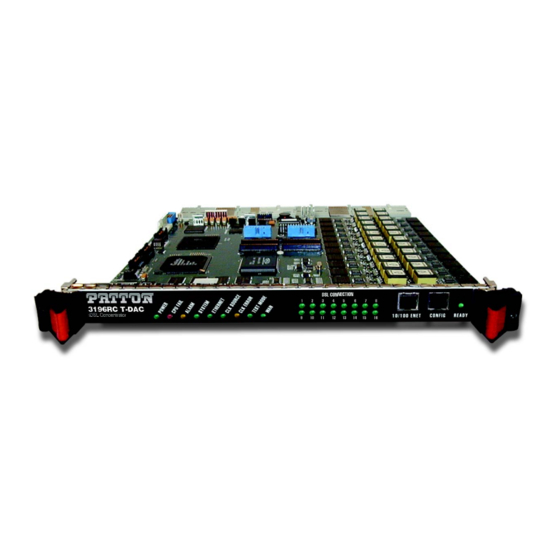
Model 3196RC T-DAC User Manual 1 • Introduction Model 3196RC iDSL T-DAC overview The Model 3196RC (see figure 2) provides 16 iDSL subscriber ports and 4, 8, 12, or 16 T1/E1 WAN uplink ports. A built-in digital cross-connect switch provides completely flexible grooming: the capability to connect any DS0-channel to any other DS0-channel from the WAN uplink ports or the iDSL ports. -
Page 18: Hardware Overview
Model 3196RC T-DAC User Manual 1 • Introduction Hardware overview The Model 3196RC combines transmission and networking technology concentrating 16 iDSL ports and 4 to 16 T1/E1 WAN links into a single slot blade for a standard CPCI chassis. The T-DAC front blade (see figure 3) contains a full set of LED status indicators presented on the front panel, and an RS-232 async control port. -
Page 19: Lan
Model 3196RC T-DAC User Manual 1 • Introduction The 10/100-Mbps Ethernet LAN port is presented on an RJ-45 connector with an auto-sensing/full-duplex 10Base-T or 100Base-T interface. Also included are: • 100Base-TX half-/full-duplex operation (100 + 100) • 10Base-T half-/full-duplex operation (10 + 10) •... -
Page 20: System Timing
Model 3196RC T-DAC User Manual 1 • Introduction System timing The iDSL T-DAC's system timing may be derived from an internal clock from an on-board chip, a CPE iDSL modem, a network clock from one of the T1/E1 WAN ports, or an external 64-kHz BITS (building integrated timing supply) reference clock. -
Page 21: Led Display
Model 3196RC T-DAC User Manual 1 • Introduction POWER LED CPU LED ALARM LED SYSTEM LED ETHERNET LED CLK SOURCE LED CLK ERROR LED TEST MODE LED WAN LED DSL CONNECTION LEDs 10/100 ENET port CONFIG port READY Figure 4. Model 3196RC front panel LEDs LED display Front panel LEDs (figure 3) display the status of the WAN ports, the iDSL ports, the Ethernet LAN port, power, and the alarms. - Page 22 Model 3196RC T-DAC User Manual 1 • Introduction Table 3. LED definitions (Continued) Color Status Meaning CLK SOURCE Green On solid The 3196RC is set as the Master Clock source. Flashing The 3196RC is set as the secondary clock source. The 3196RC is set as the slave, getting its clock from the H.110 Bus.
-
Page 23: Approvals
Model 3196RC T-DAC User Manual 1 • Introduction Approvals The Model 3196RC T-DAC has achieved the following approvals and certifications: • Safety UL 60950 Industry Canada CSA C22.2 No. 60950 • RTTE Directive (CE Mark) EMC Directive 89/336/EEC Low Voltage Directive 73/23/EEC (EN 60950) ETSI CTR 12 ETSI CTR 13 •... -
Page 24: Hardware Installation
Chapter 2 Hardware installation Chapter contents Introduction ................................25 Unpacking the Model 3196RC T-DAC ........................25 T-DAC blades installation.............................25 Cable installation..............................27 Connecting the Ethernet ports ........................27 Connecting the 10/100Base-T Ethernet port to an Ethernet switch or hub ..........27 Connecting the 10/100Base-T Ethernet port to an Ethernet-capable workstation or PC ........28 Connecting the EIA-561 RS-232 configuration port (DCE configured) ............28... -
Page 25: Introduction
Model 3196RC T-DAC User Manual 2 • Hardware installation Introduction This chapter contains the following procedures for installing the Model 3196RC T-DAC: Note Before installing the T-DAC, you will need to obtain the line type and encoding of the T1/E1 line from your local telephone company (Telco). •... -
Page 26: Alignment/Esd Pin And Card Handle
Model 3196RC T-DAC User Manual 2 • Hardware installation Note The T-DAC should be installed as close as possible to the termination jack provided by the Telco. The location should be well ventilated. Do not block the rack chassis’ cooling vents. 2. -
Page 27: Cable Installation
Model 3196RC T-DAC User Manual 2 • Hardware installation Cable installation This section describes installing the network interface cables. Connecting the Ethernet ports The T-DAC has a single 10/100 Ethernet interface for connection to your LAN (figure 6). The Ethernet port will autosense the correct speed of the local LAN and automatically negotiate half or full-duplex operation. -
Page 28: Connecting The 10/100Base-T Ethernet Port To An Ethernet-Capable Workstation Or Pc
Model 3196RC T-DAC User Manual 2 • Hardware installation Figure 7. Ethernet RJ-45 pin and signal definitions for T-DAC Connecting the 10/100Base-T Ethernet port to an Ethernet-capable workstation or PC The 10/100Base-T Ethernet port can connect to a single Ethernet-capable workstation or PC by means of a cross over cable. -
Page 29: Connecting To The T1/E1 Wan Ports
Model 3196RC T-DAC User Manual 2 • Hardware installation Connecting to the T1/E1 WAN ports An active T1/E1 is not necessary to configure the T-DAC. However, an active T1/E1 connection is required when mapping iDSL modems to specific time slots in the T1/E1 ports or even for mapping WAN time slots to other WAN time slots. -
Page 30: Wan Cable's 68 Non-Terminated Twisted-Pairs
Model 3196RC T-DAC User Manual 2 • Hardware installation 2. The other end of the cable has 68 non-terminated twisted-pairs for connection to a punch-down block (see table 4). Select the twisted pairs for the WAN ports that will be activated and terminate them on the punch-down block. -
Page 31: Connecting The Idsl Ports
Model 3196RC T-DAC User Manual 2 • Hardware installation Connecting the iDSL ports The remote (CPE) iDSL modems are connected to the T-DAC via the RJ-21X cable (see figure 12). Pin 1 50-pin TELCO Male Figure 12. RJ-21X connector 1. Connect the RJ-21X connector of the cable into the 50-pin RJ-21X receptacle on the rear of the 3196RC. 2. -
Page 32: Connecting The Bits Clock
Model 3196RC T-DAC User Manual 2 • Hardware installation Table 5. Band Marked Color Code (Continued) DSL Port 50 Pin Positions Wire Color Code Orange/Black Port 12 Black/Orange Green/Black Port 13 Black/Green Brown/Black Port 14 Black/Brown Slate/Black Port 15 Black/Slate Blue/Yellow Port 16 Yellow/Blue... -
Page 33: Ext Clock Connector Location
Model 3196RC T-DAC User Manual 2 • Hardware installation Note To synchronize the ForeFront system with a BITS clock, you must connect the site BITS clock system to the EXT CLOCK connector located on the rear-panel of the T-DAC WAN Access Module rear card (see figure 13). -
Page 34: Completing The Hardware Installation
Model 3196RC T-DAC User Manual 2 • Hardware installation Completing the hardware installation This section verifies that the T-DAC hardware is operational to the point where you can begin configuring the software settings. Power is delivered from the CPCI chassis backplane through the 47-pin PICMG 2.11 power connectors on the 3196RC blades. -
Page 35: Configuring The T-Dac For Operation
Chapter 3 Configuring the T-DAC for operation Chapter contents Introduction ................................36 Configuration prerequisites ...........................36 Initial configuration through the RS-232 control port...................37 Connecting the DB9-RJ45 adapter with the included cable ................37 Setting up the HyperTerminal (or similar program) session ................38 Using a browser to complete Model 3196RC configuration ..................41 Displaying the T-DAC 3196RC web administration pages ................41... -
Page 36: Introduction
Model 3196RC T-DAC User Manual 3 • Configuring the T-DAC for operation Introduction This chapter contains the following procedures that describe configuring the Model 3196RC T-DAC for operation: • “Configuration prerequisites”—lists the items you need to have on hand before configuring the T-DAC. •... -
Page 37: Initial Configuration Through The Rs-232 Control Port
Model 3196RC T-DAC User Manual 3 • Configuring the T-DAC for operation • If you are using a T1 WAN line, you will need the following information from the telephone company (central office): Line Type: either ESF or D4 Line Coding: either B8ZS or AMI •... -
Page 38: Setting Up The Hyperterminal (Or Similar Program) Session
Model 3196RC T-DAC User Manual 3 • Configuring the T-DAC for operation Setting up the HyperTerminal (or similar program) session Do the following: 1. At your PC, find the file HYPERTRM.EXE. Open a HyperTerminal session by double-clicking on the file name. Figure 15. -
Page 39: Com1 Properties Window
Model 3196RC T-DAC User Manual 3 • Configuring the T-DAC for operation 6. Configure your COM port settings as shown in figure 17, then click Figure 17. COM1 Properties window 7. Click on the menu, then select Properties. File 8. Configure the settings for Function, arrow and ctrl keys act as to Terminal keys as shown in figure 18, then click... -
Page 40: Login Window
Model 3196RC T-DAC User Manual 3 • Configuring the T-DAC for operation 9. Connect the male end of the 3196RC T-DAC’ power cables to the power outlets. 10. Boot up information will display on your HyperTerminal connection window, eventually followed by a login request window (see figure 19). -
Page 41: Using A Browser To Complete Model 3196Rc Configuration
Model 3196RC T-DAC User Manual 3 • Configuring the T-DAC for operation 19. Press the left-arrow cursor key until the TOP LEVEL MANAGEMENT window displays. 20. Select for Home, then press <Enter> 21. Under the Current Status page, type (store Config(1)) to save the changes you have just made to the con- figuration. -
Page 42: Home
Model 3196RC T-DAC User Manual 3 • Configuring the T-DAC for operation 5. The 3196RC Configuration Menu home page will appear (see figure 21). Figure 21. 3196RC Configuration Menu home page Home page overview HOME Configuration Menu Configuration/informa- window is divided into two panes: the pane and the tion Configuration Menu... -
Page 43: Home Page Window Panes
Model 3196RC T-DAC User Manual 3 • Configuring the T-DAC for operation Configuration Menu pane Configuration/information pane Figure 22. HOME page window panes Figure 23. Immediate Actions buttons Home From the page, the following actions can be performed: • Record Current Configuration—clicking on this button (see figure 23) saves the current configuration from volatile DRAM memory to FLASH memory. -
Page 44: Configuring The Default Gateway
Model 3196RC T-DAC User Manual 3 • Configuring the T-DAC for operation figuration changes will be lost if the power to the Model 3196RC is turned off. • Hard Reset—this button (see figure 23) causes the Model 3196RC to perform a cold restart. When you select Hard Reset, the T-DAC confirms that you want to execute this command. -
Page 45: Configuring The System Clocking Parameters
Model 3196RC T-DAC User Manual 3 • Configuring the T-DAC for operation 4. To enter the default gateway, use the first . The Destination shall remain 0.0.0.0, and there Add a route line is no mask to enter. 5. In the Gateway box, type your default gateway IP address for the 3196RC. 6. -
Page 46: System Clocking Configuration Page, Example 1
Model 3196RC T-DAC User Manual 3 • Configuring the T-DAC for operation Unless it fails or becomes disconnected, the main reference provides the system clock for the 3196RC. Should this failure occur, the fallback reference will be the clocking source for the 3196RC’s system clock. Example 1 Your 3196RC is the only blade in the chassis and must be configured as the system clocking master. -
Page 47: Configuring The Ds0 Mapping
Model 3196RC T-DAC User Manual 3 • Configuring the T-DAC for operation 2. Click the System Clocking hyperlink on the 3196RC Configuration Menu to open the System Clocking Configuration page (see figure 27). Figure 27. System Clocking Configuration page, example 2 3. -
Page 48: Ds0 Mapping Configuration Window
Model 3196RC T-DAC User Manual 3 • Configuring the T-DAC for operation The DS0 Mapping window (Digital Cross Connect Configuration) provides full DS0 grooming and supports three variations. You may define connections between (1) an iDSL modem and a WAN port, (2) two iDSL modems, or (3) two WAN time slots. -
Page 49: Examples For Configuring Static Connections
Model 3196RC T-DAC User Manual 3 • Configuring the T-DAC for operation The following notation should be used for assigning timeslots: • dash: (-), e.g., 1-3 • comma: (,), e.g., 1,4,9 • combo: 1-2,3,6-7 Examples for configuring static connections. Three examples are provided: •... -
Page 50: Idsl Port Configuration Page
Model 3196RC T-DAC User Manual 3 • Configuring the T-DAC for operation 8. On the 3196RC Configuration Menu, click the iDSL hyperlink to open the page iDSL Port Configuration (figure 30). Using your mnemonic naming convention scheme, enter a name for this connection in the Circuit ID field to the right of Port #3 (optional). -
Page 51: Idsl Port 1 Details Page
Model 3196RC T-DAC User Manual 3 • Configuring the T-DAC for operation 9. On the Configuration/information pane, click on the number 3 under the column titled Port # to open page (see figure 31). iDSL Port 3 Details Figure 31. iDSL Port 1 Details page 10. - Page 52 Model 3196RC T-DAC User Manual 3 • Configuring the T-DAC for operation Connect an E1 line, (WAN) Port 2, timeslots 1 - 31, to another E1 line, (WAN) Port 3, timeslots 1 - 31. Solution: 1. Under Dev Type A, select t1-e1(1). 2.
- Page 53 Model 3196RC T-DAC User Manual 3 • Configuring the T-DAC for operation 15. Click the Submit button at the bottom of the page. 16. Repeat steps 9 through 15 for iDSL modem port 16. You have completed the configuration for example 3. Example 4 Mapping between different blades.
-
Page 54: Activating The Idsl Ports
Model 3196RC T-DAC User Manual 3 • Configuring the T-DAC for operation Activating the iDSL ports Do the following to activate an iDSL port: 1. On the 3196RC Configuration Menu, click the DSL hyperlink to display the iDSL Port Configuration page (see figure 33). - Page 55 Model 3196RC T-DAC User Manual 3 • Configuring the T-DAC for operation • Front panel switches • DTE test mode • User ID Do the following to configure the iDSL port parameters on the Patton CPE device: 1. On the 3196RC home page click the DSL hyperlink to display the iDSL Port Configuration page. Using a browser to complete Model 3196RC configuration...
- Page 56 Model 3196RC T-DAC User Manual 3 • Configuring the T-DAC for operation 2. Scroll to the table row for the port which connects to the Patton CPE device, and click the port number hyperlink to display the iDSL Port # Details page. Using a browser to complete Model 3196RC configuration...
-
Page 57: Configuring Line Settings And Signaling For E1
Model 3196RC T-DAC User Manual 3 • Configuring the T-DAC for operation 3. Click the [change configuration] button to display the configurable parameters for the Patton CPE device on the right-hand side of the page (see below). 4. Use the drop-down menus to set the configurable parameters to your desired values. 5. -
Page 58: Configuring The E1 Line Interface Settings
Model 3196RC T-DAC User Manual 3 • Configuring the T-DAC for operation Figure 35. T1/E1 Link Activity Ports 1 – 4 page. 3. Click the Configuration… hyperlink then click the Modify Configuration... hyperlink to open the WAN Circuit CONFIGURATION LINK window (see figure 36) and view the Line Interface Settings. -
Page 59: Line Coding Pull-Down Menu With Dsx1Hdb3(3) Selected
Model 3196RC T-DAC User Manual 3 • Configuring the T-DAC for operation 2. From the Line Coding pull-down menu (figure 38) select dsx1AMI(5) or dsxHDB3(3). Most installations will use HDB3. Figure 38. Line Coding pull-down menu with dsx1HDB3(3) selected 3. From the Line Build Out pull-down menu (figure 39) select e1pulse(1). -
Page 60: Configuring Line Settings And Signaling For T1
Model 3196RC T-DAC User Manual 3 • Configuring the T-DAC for operation Configuring line settings and signaling for T1 Accessing the Line Interface Settings 1. On the 3196RC Configuration Menu, click the T1/E1 Link hyperlink to open the T1/E1 LINK ACTIV- ITY OVERVIEW page (figure 41). -
Page 61: Configuring The T1 Line Settings
Model 3196RC T-DAC User Manual 3 • Configuring the T-DAC for operation 3. Click the Configuration… hyperlink, then click the Modify Configuration... hyperlink to open the WAN Circuit CONFIGURATION LINK window (figure 43) and view the Line Interface Settings. Figure 43. WAN Circuit Configuration page, Line Interface Settings Configuring the T1 line settings 1. -
Page 62: Line Coding Pull-Down Menu With Dsx1B8Zs(2) Selected
Model 3196RC T-DAC User Manual 3 • Configuring the T-DAC for operation 2. From the Line Coding pull-down menu (figure 45), select dsx1B8ZS(2) or dsx1AMI(5). Figure 45. Line Coding pull-down menu with dsx1B8ZS(2) selected 3. From the Line Build Out pull-down menu (figure 46) select t1pulse0dB(1). -
Page 63: Saving Your Configuration
Model 3196RC T-DAC User Manual 3 • Configuring the T-DAC for operation Saving your configuration At this point you have completed the basic configuration of your T-DAC for operation. To save your configu- ration settings in non-volatile RAM, do the following: 1. -
Page 64: Import/Export
Model 3196RC T-DAC User Manual 3 • Configuring the T-DAC for operation Note The parameters that will be exported are the power-up settings as they are stored in flash memory and may not be the current operating parameters. To ensure that you export the most current parameters, go to HOME, then under Immediate Actions, click on the Record Current Configuration button. -
Page 65: Backing Up The Configuration Store In Flash Memory
Model 3196RC T-DAC User Manual 3 • Configuring the T-DAC for operation Backing up the configuration store in flash memory 1. To make a back-up copy of the configuration file currently stored in your T-DAC’s flash memory: – On the Import/Export page (figure 50) click the Export Flash... -
Page 66: Completing The Installation
Model 3196RC T-DAC User Manual 3 • Configuring the T-DAC for operation – To save the displayed data as a text file, use your browser’s Save function (figure 51). Using Netscape or Internet Explorer, for example. • Click the File menu. •... - Page 67 Model 3196RC T-DAC User Manual 3 • Configuring the T-DAC for operation Note If the T-DAC does not behave as described, the most likely cause is that the T-DAC default settings are not compatible with the T1/E1 line. If this is the case, use the RS-232 CONFIG port to correct the T-DAC settings.
-
Page 68: Operation And Shutdown
Chapter 4 Operation and shutdown Chapter contents Introduction ................................69 Activating the Model 3196RC..........................69 De-activating the Model 3196RC .........................69... -
Page 69: Introduction
Model 3196RC T-DAC User Manual 4 • Operation and shutdown Introduction This chapter describes how to start up and power down the Model 3196RC. Activating the Model 3196RC The Model 3196RC is activated by completing the procedures in chapter 2, “Hardware installation”... -
Page 70: Troubleshooting And Maintenance
Chapter 5 Troubleshooting and maintenance Chapter contents Introduction ................................71 Fault analysis .................................72 Basic iDSL and T1/E1 test modes .........................74 iDSL port test modes ............................74 Local loop ..............................74 Remote loop ..............................75 Line Loop ..............................76 T1/E1 port test modes ............................77 DSX1 payload loop (dsx1PayloadLoop) ....................77 DSX1 line loop (dsxLineLoop) ........................78... -
Page 71: Introduction
Model 3196RC T-DAC User Manual 5 • Troubleshooting and maintenance Introduction This chapter describes troubleshooting and fault analysis that can be performed by the operator. If you require more help, refer to chapter 6, “Contacting Patton for assistance” on page 85. Refer to table 7 for a list of com- mon symptoms and suggested remedies. -
Page 72: Fault Analysis
Model 3196RC T-DAC User Manual 5 • Troubleshooting and maintenance Fault analysis The following procedures outline steps you should follow when troubleshooting a Model 3196RC malfunction. 1. If possible, talk to the person who filed the trouble complaint and determine the operational symptoms. Record the symptoms on the appropriate trouble report form (include the front panel LED indications). - Page 73 Model 3196RC T-DAC User Manual 5 • Troubleshooting and maintenance Table 8. LED definitions (Continued) Location Color Status Meaning SYSTEM Front Green Flash- The Model 3196RC is operating normally. No action rec- panel ommended. The Model 3196RC is not functioning properly. As soon as possible, unplug both power cables from the Model 3196RC, wait 30 seconds, then plug the cables back into the Mode 3196RC to see if the problem disappears.
-
Page 74: Basic Idsl And T1/E1 Test Modes
Model 3196RC T-DAC User Manual 5 • Troubleshooting and maintenance Table 8. LED definitions (Continued) Location Color Status Meaning Front Panel Green On solid Indicates normal activity at each of the T1/E1/PRI links. No action recommended. Single Indicates that the Model 3196RC is detecting the network, but Flash is unable to synchronize with it. -
Page 75: Remote Loop
Model 3196RC T-DAC User Manual 5 • Troubleshooting and maintenance DSL port T1/E1 port 1 3196RC Figure 52. Local loopback To select local loop go to the iDSL page and find the port to be placed under loopback. Locate the Test Mode drop down menu and select local Loop(1) -
Page 76: Line Loop
Model 3196RC T-DAC User Manual 5 • Troubleshooting and maintenance To activate remote loop, do the following: 1. Go to the iDSL page and find the port to be placed under loopback. 2. Locate the Test Mode drop down menu and select remoteLoop(2) 3. -
Page 77: T1/E1 Port Test Modes
Model 3196RC T-DAC User Manual 5 • Troubleshooting and maintenance T1/E1 port test modes The 3196RC offers a number of diagnostics tools to test operation and performance of the T1/E1 ports and line. Diagnostics include DSX1 payload loop and DSX1 line loop. DSX1 payload loop (dsx1PayloadLoop) When activated, the received signal at the selected T1/E1 port, will be looped through the 3196RC (see figure... -
Page 78: Dsx1 Line Loop (Dsxlineloop)
Model 3196RC T-DAC User Manual 5 • Troubleshooting and maintenance DSX1 line loop (dsxLineLoop) When activated, data received at the selected T1/E1 port, is looped back to the originating device (see figure 56). Data is looped at the T1/E1 port. T1/E1 port 3196RC Figure 56. -
Page 79: Maintenance
Model 3196RC T-DAC User Manual 5 • Troubleshooting and maintenance Maintenance This section describes replacing the Model 3196RC. Replacing the Model 3196RC If you isolate a problem to the a Model 3196RC component, the entire Model 3196RC must be replaced as follows. -
Page 80: Import/Export
Model 3196RC T-DAC User Manual 5 • Troubleshooting and maintenance 2. On the Configuration Menu pane, click the Import/Export hyperlink to display the Import/Export page (figure 57). Figure 57. IMPORT/EXPORT page Maintenance... -
Page 81: Example T-Dac Flash Memory Configuration File Displayed In A Browser
Model 3196RC T-DAC User Manual 5 • Troubleshooting and maintenance 3. To make a back-up copy of the configuration file currently stored in your T-DAC’s flash memory: – On the Import/Export page (figure 57 on page 80) click the Export Flash... hyperlink. The T-DAC will get the configuration file currently stored in your T-DAC’s flash memory and display it in your browser (see figure... -
Page 82: Removing The Defective Model 3196Rc
Model 3196RC T-DAC User Manual 5 • Troubleshooting and maintenance – To save the displayed data as a text file, use your browser’s Save function (see figure 59). Using Netscape or Internet Explorer, for example. • Click the File menu. •... -
Page 83: Installing The Replacement Model 3196Rc
Model 3196RC T-DAC User Manual 5 • Troubleshooting and maintenance 3. Unlock the handles by pressing the red button on each handle. The button immediately activates the switch (turning it to an open position), while the button itself remains depressed. The blade can then be removed. -
Page 84: Completing The Installation
Model 3196RC T-DAC User Manual 5 • Troubleshooting and maintenance Completing the installation This section verifies that the Model 3196RC is fully operational. 1. Verify that the green POWER LED is lit. If the POWER LED is flashing green, refer to section “Fault anal- ysis”... -
Page 85: Contacting Patton For Assistance
Chapter 6 Contacting Patton for assistance Chapter contents Introduction ................................86 Contact information..............................86 Warranty Service and Returned Merchandise Authorizations (RMAs)..............86 Warranty coverage ............................86 Out-of-warranty service ..........................86 Returns for credit ............................86 Return for credit policy ..........................87 RMA numbers ..............................87 Shipping instructions ..........................87... -
Page 86: Introduction
Model 3196RC T-DAC User Manual 6 • Contacting Patton for assistance Introduction This chapter contains the following information: • “Contact information”—describes how to contact Patton technical support for assistance. • “Warranty Service and Returned Merchandise Authorizations (RMAs)”—contains information about the RAS warranty and obtaining a return merchandise authorization (RMA). -
Page 87: Return For Credit Policy
Model 3196RC T-DAC User Manual 6 • Contacting Patton for assistance Return for credit policy • Less than 30 days: No Charge. Your credit will be issued upon receipt and inspection of the equipment. • 30 to 120 days: We will add a 20% restocking charge (crediting your account with 80% of the purchase price). -
Page 88: Network Ports (Rj-21X) Connector Pin-Out
Appendix A Network Ports (RJ-21X) connector pin-out Chapter contents Introduction ................................89... -
Page 89: Introduction
Model 3196RC T-DAC User Manual A • Network Ports (RJ-21X) connector pin-out Introduction Figure 60 shows the pin-out for the RJ-21X 50-pin Telco connector. Table 9 contains the band-marked color codes for the RJ-21X 50-pin Telco connector Pin 1 50-pin TELCO Male Figure 60. - Page 90 Model 3196RC T-DAC User Manual A • Network Ports (RJ-21X) connector pin-out Table 9. Band Marked Color Code (Continued) DSL Port 50 Pin Positions Wire Color Code Slate/Black Port 15 Black/Slate Blue/Yellow Port 16 Yellow/Blue Orange/Yellow Yellow/Orange Green/Yellow Yellow/Green Brown/Yellow Yellow/Brown Slate/Yellow Yellow/Slate...
-
Page 91: Wan Network Module Connector Pinout
Appendix B WAN Network Module connector pinout Chapter contents Introduction ................................92 68-Pin Telco pinout ..............................92... -
Page 92: Introduction
Model 3196RC T-DAC User Manual B • WAN Network Module Introduction The WAN cable is 6 feet in length comprising 34 twisted pairs. One end of the cable will have the AMP con- nector 749621-7 (or equivalent) and the AMP back shell 749195-2 (or equivalent). The other end will be blunt. - Page 93 Model 3196RC T-DAC User Manual B • WAN Network Module Table 10. WAN cable’s 68 non-terminated twisted-pairs (Continued) Port/ 68 Pin Wire Color Port/ 68 Pin Wire Color Pairs Pairs Direction Positions Code Direction Positions Code Port 5/RX Tan/Brown Port 13/RX Pink/Violet Brown/Tan Violet/Pink...