Table of Contents
Advertisement
Quick Links
Advertisement
Table of Contents

Subscribe to Our Youtube Channel
Related Manuals for Patton electronics 3095


Summary of Contents for Patton electronics 3095
- Page 1 Model 3095 mDSL Digital Access and Cross-Connect System (DACS) Getting Started Guide Sales Office: +1 (301) 975-1000 Technical Support: +1 (301) 975-1007 E-mail: support@patton.com WWW: www.patton.com Document Number: 110061U Rev. C Part Number: 07MD3095-GS-C...
- Page 2 Patton Electronics Company, Inc. 7622 Rickenbacker Drive Gaithersburg, MD 20879 USA tel: +1 (301) 975-1000 fax: +1 (301) 869-9293 support: +1 (301) 975-1007 web: www.patton.com e-mail: support@patton.com Copyright © 2001 & 2002, Patton Electronics Company. All rights reserved. The information in this document is subject to change without notice. Patton Electronics assumes no liability for errors that may appear in this document.
-
Page 3: Table Of Contents
2 Hardware installation............................ 21 Introduction ................................22 Unpacking the Model 3095 DACS ........................22 DACS chassis installation ............................22 Cable installation..............................23 Installing the power cables—AC Power Supply ....................23 Installing the power cables—DC Power Supply ....................24 Grounding the Model 3095—AC and DC Power Supplies ................25... - Page 4 Connecting the DB9-RJ45 adapter with the included cable ................33 Setting up the HyperTerminal (or similar program) session ................33 Using a Web browser to complete Model 3095 configuration ................36 Displaying the DACS 3095 Web Administration Pages ..................37 Home page overview ..........................37 Configuring the DS0 mapping ........................39...
- Page 5 Model 3095 mDSL DACS Getting Started Guide Contents Using the DB9-RJ45 adapter with the included cable ................60 Setting up the HyperTerminal (or similar program) session ..............61 Completing the installation ........................64 6 Contacting PATTON for assistance ......................65 Introduction ................................66 Contact information..............................66 Warranty Service and Returned Merchandise Authorizations (RMAs)..............66...
- Page 6 Contents Model 3095 mDSL DACS Getting Started Guide...
-
Page 7: Compliance Information
The Model 3095 has been tested and found to comply with the limits for a Class A computing device in accordance with the specifications in Subpart B of Part 15 of FCC rules, which are designed to provide reason- able protection from such interference in a commercial installation. -
Page 8: Fcc Part 68 Compliance Statement
Model 3095 mDSL DACS Getting Started Guide you must notify the telephone company prior to disconnection. The following information may be required when applying to your local telephone company for leased line facilities. The Universal Service Order Code (USOC) is RJ48. The Facility Interface Codes (FIC) are 04DU9-BN, 04DU9-DN, 04DU9-1KN, and 04DU9-1SN. -
Page 9: About This Guide
About this guide This guide describes installing and configuring a Patton Electronics Model 3095 mDSL Digital Access and Cross-Connect System (DACS). By the time you are finished with this guide, your DACS will be connected to the remote DSL modems and transferring data. The instructions in this guide are based on the following assumptions: •... -
Page 10: Precautions
Model 3095 mDSL DACS Getting Started Guide Precautions Notes and cautions, which have the following meanings, are used throughout this guide to help you become aware of potential DACS problems. Warnings relate to personal injury issues, and Cautions refer to potential property damage. -
Page 11: Mouse Conventions
Model 3095 mDSL DACS Getting Started Guide Mouse conventions The following conventions are used when describing mouse actions: Table 2. Mouse conventions Convention Meaning Left mouse button This button refers to the primary or leftmost mouse button (unless you have changed the default configuration). - Page 12 Model 3095 mDSL DACS Getting Started Guide...
-
Page 13: Introduction
Chapter 1 Introduction Chapter contents Model 3095 mDSL DACS overview ........................14 Hardware overview ..............................15 WAN ................................15 LAN ................................15 RS-232 control port ............................16 Power system ..............................16 Central processing unit ...........................16 mDSL Ports ..............................16 Alarm Port ..............................16 System Timing and Clock Port ........................17 Temperature ..............................17... -
Page 14: Model 3095 Mdsl Dacs Overview
Each WAN port terminates T1/E1 with flexible any-to-any DS0 mapping. The entire system can be managed through SNMP/HTTP-based management screens. The Model 3095 connects 16 mDSL remote NTUs or modems at data-rates up to 2.3 Mbps to digital (ATM/ FR/DDN/IP) networks, thus permitting multi-service access to CLECs, ISPs, and PTTs. -
Page 15: Hardware Overview
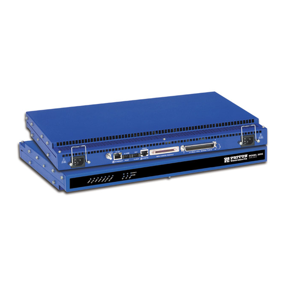
Figure 2. Model 3095 DACS features The 3095 includes four to sixteen WAN uplink ports selectable for T1 or E1 operation to ATM/FR/DDN/IP network backbones. Also included are: • Four to sixteen built-in T1/E1 CSU/DSUs •... -
Page 16: Rs-232 Control Port
Optional DC power supply with -36 to 72VDC via 2-position power block Central processing unit The 3095 employs an Intel i960VH RISC processor operating at 100 MHz/100 Mips. The CPU controls the memory, front/back-panel and management interface for mDSL port/WAN time slot mapping, local switch- ing, loopback and the management system. -
Page 17: System Timing And Clock Port
Model 3095 mDSL DACS Getting Started Guide 1 • Introduction • 3-pin terminal block connector • 3-contact dry relay for external alarm systems System Timing and Clock Port The mDSL Multiplexer's system timing may be derived from the external reference Clock Port, an Internal Clock from an on-board chip, a CPE mDSL modem, or a Network Clock from one of the T1/E1 WAN ports. -
Page 18: Management Services
2.3 Mbps m DSL MODEM PORTS 2 AMP ETHERNET CONFIG 17 in. (43 cm) Figure 3. Model 3095 DACS chassis physical dimensions Management services • Out-of-Band RS-232 configuration port for management and control • SNMP version 1 configuration management •... -
Page 19: Led Display
• EXT. CLOCK: Green if the mDSL Digital Cross Connect is being driven by the BITS clock. Off if the Model 3095 is connected to a (T1/E1) Network Clock or Internal Clock. • TEST MODE: Yellow if any of the 16 DSL ports or any of the T1/E1 ports are in local switching or loop- back mode, respectively. -
Page 20: Approvals
• WAN PORTS: Green indicates normal activity for each T1/E1 link. Red indicates an error on the port (e.g., loss of sync, etc.). Approvals The Model 3095 DACS has achieved the following approvals and certifications: • Safety UL1950 (MET) Industry Canada (cMET) •... -
Page 21: Hardware Installation
Installing the power cables—AC Power Supply ....................23 Installing the power cables—DC Power Supply ....................24 Grounding the Model 3095—AC and DC Power Supplies ................25 Connecting the Ethernet ports ........................26 Connecting the 10/100Base-T Ethernet port to an Ethernet switch or hub ..........26 Connecting the 10/100Base-T Ethernet port to an Ethernet-capable workstation or PC .........27... -
Page 22: Introduction
2 • Hardware installation Model 3095 mDSL DACS Getting Started Guide Introduction This chapter contains the following procedures for installing the Model 3095 DACS: Note Before installing the DACS, you will need to obtain the line type and encoding of the T1/E1 line from your local telephone company (telco). -
Page 23: Cable Installation
Model 3095 mDSL DACS Getting Started Guide 2 • Hardware installation 4. Place the DACS at the desired position in the rack. 5. Secure the DACS in position with the mounting screws. Cable installation This section describes installing the power, ground, and network interface cables. -
Page 24: Installing The Power Cables-Dc Power Supply
1. Connect the earth ground of the DC source to the grounding stud on the DACS as described in the fol- lowing section “Grounding the Model 3095—AC and DC Power Supplies”. 2. Strip back the insulation on each of the wires approximately -inch. -
Page 25: Grounding The Model 3095-Ac And Dc Power Supplies
Figure 7. DC connector, - DC and + DC Input view 4. Repeat steps 1 through 3 to install the remaining DC power connection. Grounding the Model 3095—AC and DC Power Supplies Do the following: 1. Assemble a ground wire using #10 AWG wire with green-colored insulation and two ring terminals. Make the wire long enough to reach one of the following ground sources: –... -
Page 26: Connecting The Ethernet Ports
(EIA-561) 10/100 Ethernet (RJ-45 connector) Figure 8. Model 3095 network and configuration ports Connecting the 10/100Base-T Ethernet port to an Ethernet switch or hub The 10/100Base-T Ethernet port (see figure 8) is designed to connect to an Ethernet switch or hub. The Ether- net RJ-45 pin and signal definitions for the DACS or for a NIC card in a workstation/PC are shown in... -
Page 27: Connecting The 10/100Base-T Ethernet Port To An Ethernet-Capable Workstation Or Pc
1 mile (1.6 km) from the digital services termination. 1. Connect the 68-pin SCSI connector of the WAN cable to the connector on the rear panel of the Model 3095. Refer to “Appendix B” on page 73 for the T1/E1 connector and pin number designations. Cable installation... -
Page 28: Connecting The Mdsl Ports
1. Connect the RJ-21X connector of the cable into the 50-pin RJ-21X receptacle on the rear of the 3095. 2. The other end of the cable has 25 non-terminated twisted-pairs for connection to punch-down blocks. - Page 29 Model 3095 mDSL DACS Getting Started Guide 2 • Hardware installation 1. Connect the equipment to a 40–72 VDC, 2.5A supply source that is electrically isolated from the AC source. The 40–72 VDC source is to be reliably connected to earth.
- Page 30 2 • Hardware installation Model 3095 mDSL DACS Getting Started Guide Completing the hardware installation...
-
Page 31: Configuring The Dacs For Operation
Connecting the DB9-RJ45 adapter with the included cable ................33 Setting up the HyperTerminal (or similar program) session ................33 Using a Web browser to complete Model 3095 configuration ................36 Displaying the DACS 3095 Web Administration Pages ..................37 Home page overview ..........................37 Configuring the DS0 mapping ........................39... -
Page 32: Introduction
• “Saving your configuration” on page 47—tells you how to save the configuration settings. • “Completing the installation” on page 49—describes testing the 3095 DACS to verify that it is fully opera- tional. Configuration prerequisites You will need the following to configure the 3095 DACS: •... -
Page 33: Initial Configuration Through The Rs-232 Control Port
Line Type: either E1 or E1-CRC Line Coding: either HDB3 or AMI Initial Configuration through the RS-232 Control Port Initially you must configure the 3095’s IP address and—in rare instances—change the netmask from the default settings. Note Do not connect power or the Ethernet connection to the Model 3095 at this time. - Page 34 3 • Configuring the DACS for operation Model 3095 mDSL DACS Getting Started Guide Figure 13. Connect To window 3. On the Connect To window (see figure 13), set Connect using: to one of the options named Direct to ComX (where the "X"...
- Page 35 Figure 15. Terminal keys configuration 9. Connect the male end of the 3095 DACS’ power cables to the power outlets. 10. On your HyperTerminal connection window, boot up information will display, eventually followed by a login request window resembling that shown in figure 16.
-
Page 36: Using A Web Browser To Complete Model 3095 Configuration
21. Under the Current Status page, type 1 (store Config(1)) to save the changes you have just made to the configuration. This completes the initial configuration of the Model 3095. The next steps in configuration will be done directly through Ethernet via your Web browser. -
Page 37: Displaying The Dacs 3095 Web Administration Pages
3. Start a Web browser session. In the portion of the browser window where the URL is displayed, type the IP address of the Model 3095 (for example, if the Model 3095’s IP address 123.124.221.10, you would type 123.124.221.10 in the browser’s URL area). If you do not have an IP address in your DACS, refer to “Initial Configuration through the RS-232 Control Port”... - Page 38 DRAM memory to FLASH memory. Once the configuration is saved into FLASH memory, the configuration will not be lost even if the power is cycled on the 3095. Initially, any changes made to the Using a Web browser to complete Model 3095 configuration...
-
Page 39: Configuring The Ds0 Mapping
T1 or E1 link, or another mDSL port. Each mDSL modem inside the 3095 DACS is configured by selecting the number of DS0 time slots, each time slot being 64 kbps. You may choose to map from 1 to 31 DS0 time slots in the mDSL modem. - Page 40 Device Type . This setting specifies the physical interface onto which you will be connecting. Within the Model 3095, the user has the option of selecting either a T1/E1 WAN line or an mDSL modem. The two Device Types' choices are...
-
Page 41: Examples On Configuring Static Connections
3. Under "Dev Slots A," enter 1 - 31. 4. Under "Dev Type B," select t1-e1(1). 5. Under "Dev Num B," select port3(3). 6. Under "Dev Slots B," enter 1 - 31. Using a Web browser to complete Model 3095 configuration... -
Page 42: Setting The Clocking Source
This section configures the Main Reference and Fallback Reference Clock for the 3095 DACS. You can choose any of the WAN ports, an internal oscillator or an externally provided clock for the system clock in the 3095. The Main Reference provides the 3095’s system clock unless it fails or is disconnected. Should this occur, the Fallback Reference will be the clocking source for the 3095’s system clock. -
Page 43: Activating The Mdsl Modems
Activate Port 5 - 8, or you may individually select any mDSL modem in the table. Activate an individual mDSL modem by selecting in the pull-down menu under connect(1) Desired State . After you have activated all desired modems, click on Submit Query Using a Web browser to complete Model 3095 configuration... -
Page 44: Configuring The Default Gateway
3. To enter the default gateway, use the first Add Route line. The Destination shall remain as 0.0.0.0. There is no mask to enter. 4. Enter the IP address in the Gateway box. This is the default gateway. 5. Click on the button. Add Route Using a Web browser to complete Model 3095 configuration... -
Page 45: Configuring Line Settings And Signaling For E1
Figure 25. T1/E1 Link Activity window Configuring line settings and signaling for E1 T1/E1 Link Configuration Menu T1/E1 Link Activity Overview 1. Select on the . The window appears (see figure 25). Using a Web browser to complete Model 3095 configuration... -
Page 46: Configuring The E1 Line Settings
At this point, the WAN front panel LEDs will become active. A solid green FRAME light indicator means that the DACS has synchronized with the E1 line. If the E1 line is not connected to the 3095, you will see Alarms on that WAN port. -
Page 47: Configuring The Line Settings
At this point, the WAN front panel LEDs will become active. A solid green FRAME light indicator means that the DACS has synchronized with the T1 line. If the T1 line is not connected to the 3095, you will see Alarms on that WAN port. - Page 48 3 • Configuring the DACS for operation Model 3095 mDSL DACS Getting Started Guide Figure 27. Import/Export main window Export Flash Import/Export 5. To export the flash configuration, click on the link on the main page. The access server will display text configuration information resembling that shown in figure 28.
-
Page 49: Completing The Installation
Figure 29. Saving the access server flash memory configuration data as a text file Completing the installation This section verifies that the Model 3095 is fully operational. 1. Temporarily disconnect the male ends of both power cords from the power outlet. Wait 30 seconds, then plug the power cords in again. - Page 50 Congratulations! Your DACS is now installed. For more in-depth information about configuring your DACS settings, refer to the DSL DACS Administrator’s Reference Guide included on your Model 3095 CD-ROM. Otherwise, refer to Chapter 4, “Operation and shutdown” for information on activating and de-activating your Model 3095 DACS.
-
Page 51: Operation And Shutdown
Chapter 4 Operation and shutdown Chapter contents Introduction ................................52 Activating the Model 3095 ............................52 De-activating the Model 3095..........................52... -
Page 52: Introduction
2. The WAN 1 Frame LED illuminates, indicating that the Model 3095 is synchronizing with the T1/E1 signal. 3. After 5 seconds, the WAN A Error LED flashes, indicating that the Model 3095 is satisfied with the quality of the T1/E1 signal. -
Page 53: Troubleshooting And Maintenance
Periodic maintenance ............................57 Calibration ..............................57 Maintenance................................57 Replacing the Model 3095 ..........................57 Exporting the current Model 3095 configuration ..................57 Removing the defective Model 3095 ......................59 Installing the replacement Model 3095 .....................60 Verifying the hardware installation ......................60 Importing a saved configuration ........................60 Using the DB9-RJ45 adapter with the included cable ................60... -
Page 54: Introduction
CPU is unable to load the software from FLASH to RAM for operation. As soon as possible, unplug both power cables from the Model 3095, wait 30 seconds, then plug the cables back into the Mode 3095 to see if the problem disappears. If the CPU FAIL LED remains lit after the Model 3095 completes the power-up cycle, contact Patton Technical Support to determine whether the DACS needs to be replaced or not. -
Page 55: Fault Analysis
5 • Troubleshooting and maintenance Fault analysis The following procedures outline steps you should follow when troubleshooting a Model 3095 malfunction. 1. If possible, talk to the person who filed the trouble complaint and determine the operational symptoms. Record the symptoms on the appropriate trouble report form (include the front panel LED indications). - Page 56 Front panel Green On solid Indicates normal activity at each of the T1/E1/PRI links. No Enabled action recommended. Flashing Indicates that the Model 3095 is detecting the network, but is unable to synchronize with it. Indicates an error on any of the T1/E1/PRI links.
-
Page 57: Periodic Maintenance
Rear panel Yellow On solid 100 Mbps speed. No action recommended. 10 Mbps speed. No action recommended. Periodic maintenance Use a lint-free cloth to clean dust off the Model 3095 chassis. Clean the input and output vents and the fans to remove the accumulated dust. Calibration The Model 3095 requires no calibration. - Page 58 5 • Troubleshooting and maintenance Model 3095 mDSL DACS Getting Started Guide Import/ 2. To export a configuration, connect your Web browser to the Administration Pages, then click on Export under the Configuration Menu to display the Import/Export main window (see figure 30).
-
Page 59: Removing The Defective Model 3095
Figure 32. Saving the access server flash memory configuration data as a text file Removing the defective Model 3095 1. Remove the replacement Model 3095 from its shipping container and place it near where the malfunction- ing Model 3095 is located. -
Page 60: Installing The Replacement Model 3095
2. Verify that the green POWER LED is lit. Importing a saved configuration Before the Model 3095 can be configured, the IP address and the netmask needs to be set up. This setup is done through the Model 3095 RS-232 CONFIG port on the Model 3095. -
Page 61: Setting Up The Hyperterminal (Or Similar Program) Session
Do the following: 1. Open a HyperTerminal session by double-clicking on HYPERTRM.EXE. Figure 33. Connection Description window 2. Type a connection name (for example, 3095 Config), select an icon, then click figure 33 OK (see Figure 34. Connect To window 3. - Page 62 5 • Troubleshooting and maintenance Model 3095 mDSL DACS Getting Started Guide 6. Configure your COM port settings as shown in figure 35, then click Figure 35. COM1 Properties window 7. Click on the menu, then select File Properties 8. Configure the settings for Function, arrow and ctrl keys act as to Terminal keys as shown in figure 36, then click Figure 36.
- Page 63 Model 3095 mDSL DACS Getting Started Guide 5 • Troubleshooting and maintenance 9. Connect the male end of the 3095 DACS power cables to the power outlets. 10. On your HyperTerminal connection window, boot up information will display, eventually followed by a login request window resembling that shown in figure 37.
-
Page 64: Completing The Installation
3. Verify that the Link 1 Frame LED illuminates, indicating that the Model 3095 is synchronizing with the T1/E1 signal. 4. Verify that after 5 seconds, the Link A Error LED begins flashing, indicating that the Model 3095 is satis- fied with the quality of the T1/E1 signal. -
Page 65: Contacting Patton For Assistance
Chapter 6 Contacting PATTON for assistance Chapter contents Introduction ................................66 Contact information..............................66 Warranty Service and Returned Merchandise Authorizations (RMAs)..............66 Warranty coverage ............................66 Out-of-warranty service ..........................66 Returns for credit ............................66 Return for credit policy ..........................67 RMA numbers ..............................67 Shipping instructions ..........................67... -
Page 66: Introduction
6 • Contacting PATTON for assistance Model 3095 mDSL DACS Getting Started Guide Introduction This chapter contains the following information: • “Contact information”—describes how to contact PATTON technical support for assistance. • “Warranty Service and Returned Merchandise Authorizations (RMAs)”—contains information about the RAS warranty and obtaining a return merchandise authorization (RMA). -
Page 67: Return For Credit Policy
Model 3095 mDSL DACS Getting Started Guide 6 • Contacting PATTON for assistance Return for credit policy • Less than 30 days: No Charge. Your credit will be issued upon receipt and inspection of the equipment. • 30 to 60 days: We will add a 20% restocking charge (crediting your account with 80% of the purchase price). - Page 68 6 • Contacting PATTON for assistance Model 3095 mDSL DACS Getting Started Guide Warranty Service and Returned Merchandise Authorizations (RMAs)
-
Page 69: A 'Network Ports (Rj-21X) Connector Pin-Out
Appendix A ‘Network Ports (RJ-21X) connector pin-out Chapter contents Introduction ................................70... -
Page 70: Introduction
A • ‘Network Ports (RJ-21X) connector pin-out Model 3095 mDSL DACS Getting Started Guide Introduction Table 5 contains the band-marked color codes for the RJ-21X, 50-pin Telco connector. The Pair Number matches the port number on the DS0 Mapping Management page. - Page 71 Model 3095 mDSL DACS Getting Started Guide A • ‘Network Ports (RJ-21X) connector pin-out Table 5. Band Marked Color Code (Continued) Wire/Color Code Tip and Ring Pair Number 50 Pin Positions Black/Slate Tip 15 Pair 15 Slate/Black Ring 15 Yellow/Blue...
- Page 72 A • ‘Network Ports (RJ-21X) connector pin-out Model 3095 mDSL DACS Getting Started Guide Introduction...
-
Page 73: B Wan Network Module Connector Pin-Out
Appendix B WAN Network Module connector pin-out Chapter contents Introduction ................................74... -
Page 74: Introduction
B • WAN Network Module connector pin-out Model 3095 mDSL DACS Getting Started Guide Introduction Table 6 and Table 7 contain the pin-out information for the 68-pin SCSI connector. WAN NETWORK MODULE Figure 40. 68-pin SCSI connector Introduction... - Page 75 Model 3095 mDSL DACS Getting Started Guide B • WAN Network Module connector pin-out Table 6. Pin-out information listed by pin number Description Description Port # Port # TX+_D TX+_J TX-_D TX-_J RX+_D RX+_J RX-_D RX-_J RX+_C RX+_I RX-_C RX-_I...
- Page 76 B • WAN Network Module connector pin-out Model 3095 mDSL DACS Getting Started Guide Table 7. Pin-out information listed by WAN port number Description Description Port # Port # TX+_A TX+_L TX-_A TX-_L RX+_A RX+_L RX-_A RX-_L TX+_B TX+_K TX-_B...
Need help?
Do you have a question about the 3095 and is the answer not in the manual?
Questions and answers