Table of Contents
Advertisement
Quick Links
Advertisement
Table of Contents

Related Manuals for Patton electronics OnSite 1069


Summary of Contents for Patton electronics OnSite 1069
- Page 1 USER MANUAL MODEL 1069 OnSite™ VDSL2 CPE REGULATORY MODEL NUMBER: This is a Class A device and is not intended for 03342D4-001 use in a residential environment. SALES OFFICE Part# 07M1069-UM Rev. C (301) 975-1000 Revised 7/3/12 TECHNICAL SUPPORT (301) 975-1007 An ISO-9001Certified Company...
-
Page 2: Table Of Contents
CONTENTS Warranty Information ..............3 Regulatory Information ..............3 EMC Directive:................3 Low-Voltage Direcive (Safety): ............. 3 PSTN: ................... 3 Radio and TV Interference (FCC Part 15) ........3 CE Declaration of Conformity ............4 Authorized European Representative........... 4 Service..................4 Safety When Working With Electricity .......... -
Page 3: Warranty Information
1.0 WARRANTY INFORMATION Patton Electronics warrants all Model 1069 components to be free from defects, and will—at our option—repair or replace the product should it fail within one year from the first date of the shipment. This warranty is limited to defects in workmanship or materials, and does not cover customer damage, abuse or unauthorized modification. -
Page 4: Ce Declaration Of Conformity
tion. The device has been tested and found to comply with the limits for a Class A computing device in accordance with specifications in Subpart B of Part 15 of FCC rules, which are designed to provide reasonable pro- tection from such interference in a commercial installation. However, there is no guarantee that interference will not occur in a particular instal- lation. -
Page 5: Safety When Working With Electricity
1.6 SAFETY WHEN WORKING WITH ELECTRICITY • This device contains no user serviceable parts. This device can only be repaired by qualified service per- sonnel. • Do not open the device when the power cord is con- nected. For systems without a power switch and without an external power adapter, line voltages are present within the device when the power cord is connected. - Page 6 In accordance with the requirements of council direc- tive 2002/96/EC on Waste of Electrical and Electronic Equipment (WEEE), ensure that at end-of-life you sepa- rate this product from other waste and scrap and deliver to the WEEE collection system in your country for recy- cling.
-
Page 7: General Information
2.0 GENERAL INFORMATION Thank you for your purchase of this Patton Electronics product. This product has been thoroughly inspected and tested and is warranted for one year for parts and labor. If any questions or problems arise during installation or use of this product, contact Patton Electronics Technical Support at +1 (301) 975-1007. -
Page 8: Application
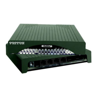
POTS/ISDN twisted-pair RJ-45 interface VDSL twisted-pair RJ-45 interface Ethernet ports (0-3) Reset switch Power jack Figure 1. Model 1069 rear panel 2.3 APPLICATION In an example application, the VDSL2 CPE modem is placed in either MxU environments or individual residents for delivering triple play ser- vices including “fiber like”... -
Page 9: Installation
3.0 INSTALLATION The Interconnecting cables shall be acceptable for external use and shall be rated for the proper applica- tion with respect to voltage, current, anticipated tem- CAUTION perature, flammability, and mechanical serviceability. To connect the Model 1069, do the following: 1. -
Page 10: Connecting The Line Interface
3.1 CONNECTING THE LINE INTERFACE The Interconnecting cables shall be acceptable for external use and shall be rated for the proper applica- tion with respect to voltage, current, anticipated tem- CAUTION perature, flammability, and mechanical serviceability. The Model 1069 supports communication over a distance of up to 10,000 ft (3 km) over 24 AWG (0.5 mm) twisted-pair wire or Cat5+. -
Page 11: Connecting The 10/100Base-T Ethernet Interface
3.2 CONNECTING THE 10/100BASE-T ETHERNET INTERFACE The Interconnecting cables shall be acceptable for external use and shall be rated for the proper applica- tion with respect to voltage, current, anticipated tem- CAUTION perature, flammability, and mechanical serviceability. The RJ-45 ports labeled Ethernet are the Auto-MDIX10/100Base-T inter- faces. -
Page 12: Connecting Power
3.4 CONNECTING POWER The Interconnecting cables shall be acceptable for external use and shall be rated for the proper applica- tion with respect to voltage, current, anticipated tem- CAUTION perature, flammability, and mechanical serviceability. The Model 1069 does not have a power switch, so it powers up as soon as it is plugged in. -
Page 13: Configuration
4.0 CONFIGURATION You may use the DIP switch included in the Model 1069 for configuring the CO or CPE mode. All other configurations for the Model 1069 VDSL2 CPE should be made through the VDSL2+ DSLAM. 4.1 CONFIGURING SWITCH S1-1: CO/CPE The DIP switches are externally accessible from the underside of the Model 2174. -
Page 14: Operation
5.0 OPERATION Once the Model 1069 is properly installed, it should operate transpar- ently. No user settings required. This section describes reading the LED status monitors. Before applying power to the Model 1069, please review section 3.4, “Connecting Power” on page 12 to verify that the unit is connected to the appropriate power source. -
Page 15: Specifications
APPENDIX A SPECIFICATIONS A.1 VDSL2 • Full compliance up to 30Mhz profile A.2 LAN CONNECTION • Four RJ-45, 10/100Base-T, IEEE 802.3 Ethernet A.3 TRANSMISSION LINE • Two-wire unconditioned twisted pair • VDSL2 Connector: RJ-45 A.4 LED STATUS INDICATORS • Power (Green) •... -
Page 16: Model 1069 Series Factory
APPENDIX B MODEL 1069 SERIES FACTORY REPLACEMENT PARTS AND ACCESSORIES Patton Model # Description Base Models 1069/EUI OnSite VDSL2 CPE RJ45 Line, 100-240VAC 07M1069-UM User Manual Power Supplies PS-03671H1-002 100-240VAC (12V, DC/2A) Wall mount power adapter Power Adapters 12-130 European replacement plug 12-129 American replacement plug 12-131... -
Page 17: Model 1069 Series Interface Pin Assignment
APPENDIX C MODEL 1069 SERIES INTERFACE PIN ASSIGNMENT C.1 10/100BASE-T INTERFACE RJ-45 • Pin 1: TX+ • Pin 2: TX- • Pin 3: RX+ • Pin 6: RX- • Pins 4, 5, 7, 8: no connection C.2 VDSL2 INTERFACE RJ-45 •... - Page 18 NOTES _________________________________________________________ _________________________________________________________ _________________________________________________________ _________________________________________________________ _________________________________________________________ _________________________________________________________ _________________________________________________________ _________________________________________________________ _________________________________________________________ _________________________________________________________ _________________________________________________________ _________________________________________________________ _________________________________________________________ _________________________________________________________...
- Page 19 NOTES _________________________________________________________ _________________________________________________________ _________________________________________________________ _________________________________________________________ _________________________________________________________ _________________________________________________________ _________________________________________________________ _________________________________________________________ _________________________________________________________ _________________________________________________________ _________________________________________________________ _________________________________________________________ _________________________________________________________ _________________________________________________________...
- Page 20 NOTES _________________________________________________________ _________________________________________________________ _________________________________________________________ _________________________________________________________ _________________________________________________________ _________________________________________________________ _________________________________________________________ _________________________________________________________ _________________________________________________________ _________________________________________________________ _________________________________________________________ _________________________________________________________ _________________________________________________________ _________________________________________________________ Copyright © 2012. Patton Electronics Company All Rights Reserved.
Need help?
Do you have a question about the OnSite 1069 and is the answer not in the manual?
Questions and answers