Table of Contents
Advertisement
Quick Links
Download this manual
See also:
User Manual
Dear Valued Customer,
Thank you for purchasing Patton Electronics products! We do appreciate
your business. I trust that you find this user manual helpful.
We manufacture one of the widest selections of data communications
products in the world including CSU/DSU's, network termination units,
powered and self-powered short range modems, fiber optic modems, interface
converters, baluns, electronic data switches, data-line surge protectors,
multiplexers, transceivers, hubs, print servers and much more. We produce
these products at our Gaithersburg, MD, USA, facility, and can custom
manufacture products for your unique needs.
We would like to hear from you. Please contact us in any of the following
ways to tell us how you like this product and how we can meet your product
needs today and in the future.
Web:
http://www.patton.com
Sales E-mail:
sales@patton.com
Support E-mail:
support@patton.com
Phone - Sales
(301) 975-1000
Phone - Support
(301) 975-1007
Fax:
(301) 869-9293
Mail:
Patton Electronics Company
7622 Rickenbacker Drive
Gaithersburg, MD 20879 USA
We are committed to a quality product at a quality price. Patton
Electronics is BABT and ISO 9001 certified. We meet and exceed the highest
standards in the industry (CE, UL, etc.).
It is our business to serve you. If you are not satisfied with any aspect of
this product or the service provided from Patton Electronics or its distributors,
please let us know.
Thank you.
Burton A.Patton
Vice President
P.S. Please tell us where you purchased this product.
USER
MANUAL
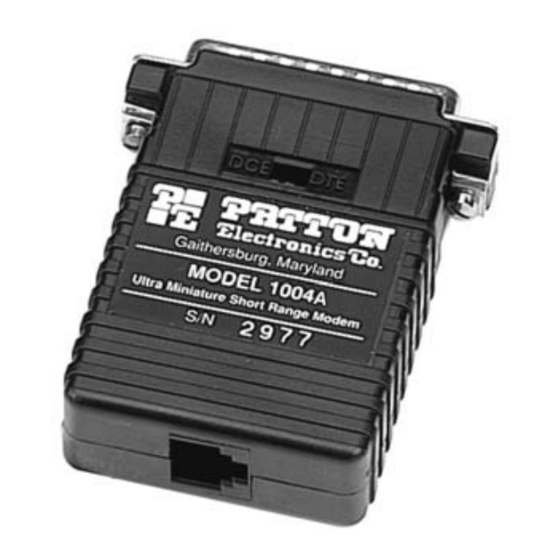
MODEL 1004A
High Speed, Multipoint
Short Range Modem
Part# 07M1004A-C
Doc# 047031UC
Revised 4/15/97
C E R T I F I E D
An ISO-9001
Certified Company
SALES OFFICE
(301) 975-1000
TECHNICAL SUPPORT
(301) 975-1007
http://www.patton.com
Advertisement
Table of Contents

Related Manuals for Patton electronics 1004A


Summary of Contents for Patton electronics 1004A
-
Page 1: User Manual
(CE, UL, etc.). It is our business to serve you. If you are not satisfied with any aspect of this product or the service provided from Patton Electronics or its distributors, please let us know. Thank you. -
Page 2: Warranty Information
The Model 1004A has been tested and found to comply with the limits for a Class A computing device in accordance... -
Page 3: General Information
Figure 2 (below) shows the location of the eight position DIP switch • Silicon Avalanche Diode surge protection on the underside of the Model 1004A PC board. Figure 3 (opposite page) shows the orientation of the eight position DIP switch, with respect to ON/OFF positions. -
Page 4: Dip Switch Settings
DCE/DTE switch. If the device connected to the Model S1-3 RTS/CTS Delay 8 msec 1004A is a modem or multiplexer (or is wired like one), set the switch to S1-4 “ECHO” Mode Echo Off “DTE”. This setting causes the Model 1004A to behave like Data Terminal Equipment and transmit data on pin 2. - Page 5 (half-duplex mode only). The switch settings generally needed to configure the Model S1-4 Setting 1004A for various applications are shown in the table below. Note: Do Echo On not change switch settings until you have carefully read Section 3.3. Echo Off...
-
Page 6: Installation
If your application requires you to connect one or two pairs of bare XMT+--------------------------------------------------XMT+ wires to the Model 1004A, you will need to open the case to access the XMT----------------------------------------------------XMT- terminal blocks. The following instructions will tell you how to open the case, connect the bare wires to the terminal blocks and fasten the strain relief collar in place so the wires won't pull loose. - Page 7 8. When you finish connecting the wires to the terminal block, the assembly should resemble the diagram below: 10. Insert the strain relief assembly and wire into the slot in the bottom half of the modem case. Set it into the recess in the case. 9.
- Page 8 4.1.2 TWISTED PAIR CONNECTION USING RJ-11 OR RJ-45 RJ-45 Cable (4-Wire) The RJ-11 and RJ-45 connectors on the Model 1004A’s twisted pair SIGNAL PIN# PIN# SIGNAL interface are pre-wired for a standard TELCO wiring environment. The signal/pin relationships are shown below: †...
-
Page 9: Daisy Chain Topology
Figure 5. Star wiring for Model 1004A host and slaves (Note: If you must use a cable to connect the Model 1004A to the RS-232 device, make sure it is a straight through cable of the shortest possible length—we recommend 6 feet or less). - Page 10 APPENDIX A APPENDIX B PATTON MODEL 1004A RS-232 PIN CONFIGURATIONS PATTON MODEL 1004 SPECIFICATIONS DIRECTION “DCE” SETTING DIRECTION Transmission Format: Asynchronous Data Rate: Up to 115,200 bps 1- (FG) Frame Ground Range: Up to 9 miles 2- (TD) Transmit Data...
Need help?
Do you have a question about the 1004A and is the answer not in the manual?
Questions and answers