Patton electronics RocketLink-G 3088 Series User Manual
G.shdsl ntu with fixed serial interface
Hide thumbs
Also See for RocketLink-G 3088 Series:
- User manual (48 pages) ,
- Quick start manual (13 pages)
Table of Contents
Advertisement
Quick Links
For Quick
Start Installation
RocketLink-G Model 3088 Series
G.SHDSL NTU with fixed
serial interface
User Manual
Important
This is a Class A device and is not intended nor approved for use in a residential environment.
Sales Office:
+1 (301) 975-1000
Technical Support:
+1 (301) 975-1007
E-mail:
support@patton.com
WWW:
www.patton.com
Part Number: 07M3088-GSG, Rev. J
Revised: February 15, 2012
Advertisement
Table of Contents

Related Manuals for Patton electronics RocketLink-G 3088 Series


Summary of Contents for Patton electronics RocketLink-G 3088 Series
-
Page 1: User Manual
For Quick Start Installation RocketLink-G Model 3088 Series G.SHDSL NTU with fixed serial interface User Manual Important This is a Class A device and is not intended nor approved for use in a residential environment. Sales Office: +1 (301) 975-1000 Technical Support: +1 (301) 975-1007 E-mail:... - Page 2 Patton Electronics Company, Inc. 7622 Rickenbacker Drive Gaithersburg, MD 20879 USA Tel: +1 (301) 975-1000 Fax: +1 (301) 869-9293 Support: +1 (301) 975-1007 Web: www.patton.com E-mail: support@patton.com Trademark Statement The term RocketLink-G is a trademark of Patton Electronics Company. All other trademarks presented in this document are the property of their respective owners.
-
Page 3: Summary Table Of Contents
Summary Table of Contents General information ............................14 2 Configuration..............................18 RocketLink-G installation..........................41 Operation ..............................51 Remote console operation ..........................55 Software Upgrade ............................60 Reset configuration to factory defaults......................62 Contacting Patton for assistance ........................64 Compliance information .......................... -
Page 4: Table Of Contents
Table of Contents Summary Table of Contents ........................... 3 Table of Contents ............................4 List of Figures ..............................8 List of Tables ..............................9 About this guide ............................10 Audience................................10 Structure................................10 Precautions ................................11 Safety when working with electricity .......................12 ..................................13 General observations... - Page 5 Model 3088 Series User Manual Table of Contents S2-2 Line Code (Models 3088/K and 3088/T) ..................31 S2-3: Annex A/B (Models 3088/K and 3088/T) ..................31 S2-4 through S2-5: Clock Mode (Models 3088/K and 3088/T)) ..............31 S2-6 through S2-8: Line Type (Models 3088/K and 3088/T) ..............32 Console ................................32...
- Page 6 Model 3088 Series User Manual Table of Contents LOS (Red) [Models K and T] ........................53 Test modes ..............................53 Loopbacks ..............................54 Patterns ..............................54 Remote console operation ..........................55 Introduction ................................56 Establishing a Remote Console Session ......................56 How to Connect ............................56 How to Disconnect ...........................57 Differences in Local and Remote Control Session Behavior ..............58...
- Page 7 Model 3088 Series User Manual Table of Contents Status LEDs................................72 Power (Green) ............................72 DSL (Green) .............................72 Link (Green) (T1/E1 only) ........................72 Term (Green) ............................73 TM/ER (Red) ............................73 Configuration................................73 Power and power supply specifications ........................73 External AC universal power supply ........................73 External 48 VDC power supply ........................74 Transmission line...
-
Page 8: List Of Figures
List of Figures RocketLink-G 3088 ..............15 Power connection barrel receptacle 5 VDC diagram . -
Page 9: List Of Tables
List of Tables General conventions ..............13 RocketLink-G configurable parameters . -
Page 10: About This Guide
About this guide This guide describes installing and operating the Patton Electronics Model 3088 G.SHDSL RocketLink-G™ NTU. Audience This guide is intended for the following users: • Operators • Installers • Maintenance technicians Structure This guide contains the following chapters and appendices: •... -
Page 11: Precautions
Model 3088 Series User Manual Precautions Notes, cautions, and warnings, which have the following meanings, are used throughout this guide to help you become aware of potential problems. are intended to prevent safety hazards that could result in per- sonal injury. are intended to prevent situations that could result in property damage or impaired functioning. -
Page 12: Safety When Working With Electricity
Model 3088 Series User Manual Safety when working with electricity • Do not open the device when the power cord is connected. For systems without a power switch and without an external power adapter, line volt- ages are present within the device when the power cord is connected. WARNING For devices with an external power adapter, the power adapter shall be a •... -
Page 13: General Observations
Model 3088 Series User Manual Electrostatic Discharge (ESD) can damage equipment and impair electrical circuitry. It occurs when electronic printed circuit cards are improperly handled and can result in complete or intermittent CAUTION failures. Do the following to prevent ESD: •... -
Page 14: General Information
Chapter 1 General information Chapter contents RocketLink-G 3088 overview..........................15 Serial interface types ..............................15 Features .................................15 Power input connector ............................16 External AC universal power supply ........................16 External 48 VDC power supply ........................17... -
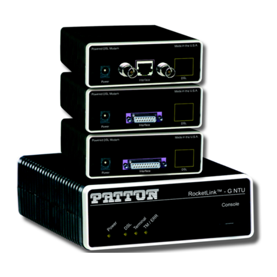
Page 15: Rocketlink-G 3088 Overview
Model 3088 Series User Manual 1 • General information RocketLink-G 3088 overview The Patton Electronics Model 3088 G.SHDSL RocketLink provides high speed 2-wire connectivity to ISPs, PTTs, and enterprise environments using Symmetrical High-data-rate Digital Subscriber Line (G.SHDSL) technology. As a symmetric DSL NTU, RocketLink DSL offers the same data rates in both directions over a single pair of regular twisted pair lines using TC-PAM modulation. -
Page 16: Power Input Connector
Model 3088 Series User Manual 1 • General information • Built-in testing and diagnostics • RocketLink Plug ‘n’ Play for easy installations • Interoperable with other Patton G.SHDSL modems • Configurable as remote (CP) units • Configurable as central (CO) units to operate back-to-back •... -
Page 17: External 48 Vdc Power Supply
Model 3088 Series User Manual 1 • General information External 48 VDC power supply The external DC adaptor shall be a listed limited power source that incorporates a disconnect device and shall be positioned within easy reach of the operator. The interconnecting cables CAUTION shall be rated for the proper voltage, current, anticipated tem- perature, flammability, and mechanical serviceability... -
Page 18: Configuration
Chapter 2 Configuration Chapter contents Introduction ................................19 Software (CLI) configuration ..........................19 Hardware (DIP-switch) configuration ......................19 Configuring the DIP switches .........................22 System reset mode ............................23 Software upgrades .............................23 Configuration reset to factory defaults .......................23 DIP switch settings ............................23 DIP switch settings for RocketLink-G models 3088/CA and 3088/D .............24 S1-1 through S1-7: Data Rate (RocketLink-G models 3088/CA and 3088/D) .........25... -
Page 19: Introduction
Model 3088 Series User Manual 2 • Configuration Introduction You can configure the RocketLink-G (see figure 3) in one of two ways: • Software configuration using command line interface (CLI) via the console port • Hardware configuration via DIP switches Figure 3. -
Page 20: Rocketlink-G Configurable Parameters
Model 3088 Series User Manual 2 • Configuration • If you attempt to modify any configuration parameters via the EOC (by changing (EOC variables), the RocketLink-G will not execute your changes. Table 2 lists the Model 3088’s configurable parameters. Table 2. RocketLink-G configurable parameters Parameter Description Possible Values... - Page 21 Model 3088 Series User Manual 2 • Configuration Table 2. RocketLink-G configurable parameters (Continued) Parameter Description Possible Values Line Code Selects line coding for the T1 or E1 line. (models K & T) HDB3 (E1 only) B8ZS (T1 only) Line Build Out Selects wave form used on the T1 or E1 line.
-
Page 22: Configuring The Dip Switches
Model 3088 Series User Manual 2 • Configuration Table 2. RocketLink-G configurable parameters (Continued) Parameter Description Possible Values DSL Error Monitor The length, in seconds, of an interval. 1–255 Interval Time DSL Error Monitor The number of errored intervals allowed before restarting the DSL 1–255 Interval Count link. -
Page 23: System Reset Mode
Model 3088 Series User Manual 2 • Configuration The two sets of DIP switches on the underside of the Model 3088 are referred to as S1 and S2. As shown in figure 5, DIP switch orientation with respect to ON and OFF positions is consistent for all switches. Figure 5. -
Page 24: Dip Switch Settings For Rocketlink-G Models 3088/Ca And 3088/D
Model 3088 Series User Manual 2 • Configuration DIP switch settings for RocketLink-G models 3088/CA and 3088/D An overview of the RocketLink-G DIP switch functions for Models 3088/CA and 3088/D is provided in table 3 table 4. The detailed switch settings are shown in following tables. Table 3. -
Page 25: S1-1 Through S1-7: Data Rate (Rocketlink-G Models 3088/Ca And 3088/D)
Model 3088 Series User Manual 2 • Configuration S1-1 through S1-7: Data Rate (RocketLink-G models 3088/CA and 3088/D) Switches S1-1 through S1-7 define both the DSL data rate and the serial data rate. Table 5. S1-1 through S1-7 Data Rate DIP switch settings S1-1 S1-2 S1-3... - Page 26 Model 3088 Series User Manual 2 • Configuration Table 5. S1-1 through S1-7 Data Rate DIP switch settings (Continued) S1-1 S1-2 S1-3 S1-4 S1-5 S1-6 S1-7 Data Rate (kbps) 2368 2432 2496 2560 2624 2688 2752 2816 2880 2944 3008 3072 3136 3200...
-
Page 27: S1-8: Tx Clock (Rocketlink-G Models 3088/Ca And 3088/D)
Model 3088 Series User Manual 2 • Configuration S1-8: TX Clock (RocketLink-G models 3088/CA and 3088/D) Table 6. S1-8 TX Clock DIP switch settings S1-8 Setting Description Normal TD sampled on falling edge of TX clock. Inverted TD sampled on rising edge of TX clock. S2-2: Line Probe (Models 3088/CA and D) Line probe is a mechanism that determines the highest rate (192K to 2304K) that the DSL link can reliably support. -
Page 28: X.21 Operation
Model 3088 Series User Manual 2 • Configuration X.21 operation. There are a few things to note about clock modes and X.21 operation. One X.21 modem must be set to Receive-Recover. The other X.21 modem must be set to either Internal or External/Network clock mode. -
Page 29: Dip Switch Settings For Rocketlink-G Models 3088/K And 3088/T
Model 3088 Series User Manual 2 • Configuration DIP switch settings for RocketLink-G models 3088/K and 3088/T An overview of the RocketLink-G DIP switch functions for Models 3088/K (E1) and 3088/T (T1) is provided table 12 table Table 12. Model 3088/K and 3088/T S1 DIP-Switch Functions Position Function S1-1... -
Page 30: S1-1 Through S1-6: Timeslots & Data Rate (Rocketlink-G Models 3088/K And 3088/T)
Model 3088 Series User Manual 2 • Configuration S1-1 through S1-6: TimeSlots & Data Rate (RocketLink-G Models 3088/K and 3088/T) Switches S1-1 through S1-6 define the number of timeslots utilized, and thus the data rate, on both the T1/E1 line and the DSL line. G.991.2 specifies G.SHDSL data rates beginning at 192 kbps. In compliance with the G.991.2 specification, the RocketLink-G will only set the number of DSL timeslots at a value greater than or equal to 3, regardless of the setting for T1/E1 timeslots Table 14. -
Page 31: S1-7 And S1-8: Line Build Out (Models 3088/K And 3088/T)
Model 3088 Series User Manual 2 • Configuration S1-7 and S1-8: Line Build Out (Models 3088/K and 3088/T) Switches S1-7 and S1-8 define the shape of the waveform on the T1 or E1 line, as shown in table Table 15. S1-7 – S1-8: Line Build Out Settings S1-7 S1-8 Line Build Out (E1) -
Page 32: S2-6 Through S2-8: Line Type (Models 3088/K And 3088/T)
Model 3088 Series User Manual 2 • Configuration Table 18. S2-4 and S2-5 Clock Mode Settings S2-4 S2-5 Clock Mode Description Reserved S2-6 through S2-8: Line Type (Models 3088/K and 3088/T) The RocketLink-G has two different line types, T1 and E1. T1 has three different settings, and E1 has five dif- ferent settings. - Page 33 Model 3088 Series User Manual 2 • Configuration External: The serial interface provides the clock for the DSL interface (V.35, X.21). It must be set to DTE for the X.21 interface. Receive Recover: The 3088 recovers the clock from the DSL interface and provides it to the serial/T1/ E1 interface.
- Page 34 Model 3088 Series User Manual 2 • Configuration • DSL Error Monitor Interval Count: The number of errored intervals allowed before restarting the DSL link. • DSL Error Monitor Total Intervals: The number of intervals to inspect before disabling the error moni- tor.
-
Page 35: Help Commands
Model 3088 Series User Manual 2 • Configuration RX FIFO Empty RX FIFO Slip • T1/E1 Loss of Signal: Active or Inactive. • T1/E1 Frame Sync: Searching or Found. • T1/E1 Frame Errors: Yes or No. • T1/E1 Buffer Slips: Yes or No. •... -
Page 36: System Configuration Commands
Model 3088 Series User Manual 2 • Configuration System Configuration Commands The following commands allow the user to configure the system: • system set password <password>: Sets the system password. • system set circuitid <circuitid>: Sets the circuit ID. • system set clockmode <internal|external/network|receiverecover>: Sets the clock mode. -
Page 37: Dsl Status Command
Model 3088 Series User Manual 2 • Configuration • DSL Error Monitor Startup Delay Interval 1 Interval 2 … Interval totint ?startdelay⇒ ?inttime⇒ ?inttime⇒ ?inttime⇒ ?inttime⇒ The DSL error monitor inspects intervals to see if they have met the error threshold (maxint). If the error mon- itor finds a certain number (intcnt) of intervals that meet or exceed the error threshold, it will restart the DSL link. -
Page 38: T1/E1 Status Commands
Model 3088 Series User Manual 2 • Configuration t1e1 set lbo <75ohm|120ohm|0.0|7.5|15.0|22.5> Select the line build out. 75? and 120? can only be use for E1 line types. The others can only be used for T1 line types. t1e1 set timeslots <1-32> Specify the number of T1/E1 timeslots to map to DSL timeslots. -
Page 39: Rocketlink Plug 'N' Play
Model 3088 Series User Manual 2 • Configuration tx fifo full: tx fifo empty: 0 tx fifo slip: tx stuff: rx fifo full: rx fifo empty: 0 rx fifo slip: line condition: good noise margin: 3.5 > remote console password: ****** >... -
Page 40: Typical Rocketlink Plug 'N' Play Application
Model 3088 Series User Manual 2 • Configuration • Set the Model 3088 (CP) to “RocketLink Plug-and-Play CP” by setting S1 and S2 DIP switches in the ON position as described in figure 3096RC 3088 DSL Span (CO) (CP) DIP Switches all in ON position DIP Switches or NMS configured according to specific application requirements... -
Page 41: Rocketlink-G Installation
Chapter 3 RocketLink-G installation Chapter contents Installation ................................42 Connecting the twisted pair interface ......................42 Connecting the Model 3088/CA (V.35) serial interface ..................43 Connecting the Model 3088/CA (V.35) to a “DTE” device ..............43 Connecting the Model 3088/CA (V.35) to a “DCE” device ..............43 Connecting the Model 3088/D (X.21) serial interface ..................44... -
Page 42: Installation
Model 3088 Series User Manual 3 • RocketLink-G installation Installation Once the Model 3088 is properly configured, it is ready to connect to the twisted pair interface, to the serial port, and to the power source. This section tells you how to make these connections. Connecting the twisted pair interface The Model 3088 supports communication between two DTE devices as follows: The interconnecting cables shall be acceptable for external use... -
Page 43: Connecting The Model 3088/Ca (V.35) Serial Interface
Model 3088 Series User Manual 3 • RocketLink-G installation Connecting the Model 3088/CA (V.35) serial interface Model 3088/CA supports V.35 serial port connections. This section describes how to connect the serial ports to your V.35 equipment. The interconnecting cables shall be acceptable for external use and shall be rated for the proper application with respect to volt- age, current, anticipated temperature, flammability, and CAUTION... -
Page 44: Connecting The Model 3088/D (X.21) Serial Interface
Model 3088 Series User Manual 3 • RocketLink-G installation circuit cable. When connecting the V.35 interface of the Model 3088/CA to your DCE device (see figure use a V.35 tail circuit cable. Some applications may also require the installation of a tail-circuit buffer to account for small differences in clock frequency between the 3088/CA and the V.35 DCE (multiplexer). -
Page 45: Opening The Case
Model 3088 Series User Manual 3 • RocketLink-G installation such as a modem or multiplexer. When connecting the X.21 interface of the Model 3088/D to your DTE or DCE device, use an X.21 straight-through cable (See figure 10). ™ i n k e t L o le DSL Span... -
Page 46: Connecting The Model 3088/K Serial Interface
Model 3088 Series User Manual 3 • RocketLink-G installation The DCE/DTE strap is located on the top side of the 3088/D pc board (See figure 12). The arrows on the top of the strap indicate the configuration of the X.21 port (for example, if the DCE arrows are pointing toward the DB-15 connector, the X.21 port is wired as a DCE). -
Page 47: Connect Twisted Pair (120 Ohm) To E1 Network
Model 3088 Series User Manual 3 • RocketLink-G installation Connect twisted pair (120 ohm) to E1 network The Model 3088/K is equipped with a single RJ-48C jack for connections to a 120 ohm twisted pair E1 net- work interface. If your E1 network terminates via RJ-48C, use the diagram below and the table following it to make the proper connections. -
Page 48: Connecting The Model 3088/T (T1) Serial Interface
Model 3088 Series User Manual 3 • RocketLink-G installation i n t r e d r f a I n t e TX (75 Ohm) E1 interface (Data to (120 Ohm) G.703/G.704 network) RX (75 Ohm) Power (Data from G.703/G.704 network) Figure 15. -
Page 49: Connecting Power
Model 3088 Series User Manual 3 • RocketLink-G installation Use the following connection diagram to connect the 120 ohm E1 network channel. RJ-48C Cable (8-Wire) 3088/T Signal Pin # Network signal RX (Ring) TX (Ring) RX (Tip) TX (Tip) Shield Shield TX (Ring) RX (Ring) -
Page 50: Dc Power
Model 3088 Series User Manual 3 • RocketLink-G installation DC Power The 36-60 VDC DC to DC adapter is supplied with the DC version of the Model 3088. The black and red leads plug into a DC source (nominal 48VDC) and the barrel power connector plugs into the barrel power supply jack on the 3088. -
Page 51: Operation
Chapter 4 Operation Chapter contents Introduction ................................52 Power-up ................................52 LED status monitors ............................52 Power (Green) ............................52 DSL (Green) .............................52 Link (Green) (Models K and T only) ......................52 Term (Green) [Models C and D] ......................53 TM/ER (Red) ............................53 LOS (Red) [Models K and T] ........................53 Test modes ..............................53... -
Page 52: Introduction
Model 3088 Series User Manual 4 • Operation Introduction Once the Model 3088 is properly configured and installed, it should operate transparently. The following sec- tions describe power-up, reading the LED status monitors, and using the built-in loopback test modes. Power-up To apply power to the Model 3088, first be sure that you have read section “Power input connector”... -
Page 53: Term (Green) [Models C And D]
Model 3088 Series User Manual 4 • Operation Term (Green) [Models C and D] The Term LED glows solid under the following circumstances: • 3088/CA with V.35 interface: If the serial interface has asserted DTR • 3088/D with the X.21 interface: Configured as DCE: Indicates that the “Control”... -
Page 54: Loopbacks
Model 3088 Series User Manual 4 • Operation Loopbacks The 3088 supports both Local Analog Loopbacks (LAL) and Remote Digital Loopbacks (RDL). These can be initiated either from the optional front panel switches or by the console command dsl set loopback <off|lal|rdl>. -
Page 55: Remote Console Operation
Chapter 5 Remote console operation Chapter contents Introduction ................................56 Establishing a Remote Console Session ......................56 How to Connect ............................56 How to Disconnect ...........................57 Differences in Local and Remote Control Session Behavior ..............58... -
Page 56: Introduction
Model 3088 Series User Manual 5 • Remote console operation Introduction The PC user (near-end) may configure and verify status of the remote 3088 (far-end) via a Remote Console session. The PC user must log onto the 3088 (near-end) unit to establish a remote console session. Once done, the remote 3088 (far-end) appears as a unit which is locally connected through the RS-232 console port. -
Page 57: How To Disconnect
Model 3088 Series User Manual 5 • Remote console operation Note The local or remote 3088 may be CO or CPE, as long as there is one of each. Either the CO or CPE unit may accept a remote console connection. Note With a remote console session open, a user at PC (far-end) is blocked from using the local console. -
Page 58: Differences In Local And Remote Control Session Behavior
Model 3088 Series User Manual 5 • Remote console operation The response upon logging out of the remote console session with the command logout is Console: Remote con- sole connection lost. The following is what is displayed upon a user’s logging out of a remote console session after logging in. - Page 59 Model 3088 Series User Manual 5 • Remote console operation • dsl set loopback lal: Do not issue this command over the RCS to the far-end 3088. If the far-end goes into LAL, the near-end and far-end 3088 NTUs can no longer communicate over the RCS. Do not issue this command to a far-end unit.
-
Page 60: Software Upgrade
Chapter 6 Software Upgrade Chapter contents Introduction ................................61... -
Page 61: Introduction
Model 3088 Series User Manual 6 • Software Upgrade Introduction The Model 3088 is software upgradeable through the console port. Software images will be available in Intel Hex file format. The software upgrade feature is available either by powering up the Model 3088 with all DIP switches set to the OFF position, or by entering the system upgrade command on the command line interface. -
Page 62: Reset Configuration To Factory Defaults
Chapter 7 Reset configuration to factory defaults Chapter contents Introduction ................................63... -
Page 63: Introduction
Model 3088 Series User Manual 7 • Reset configuration to factory defaults Introduction The configuration can be reset to factory defaults from the software reset mode. This allows a user to recover from a forgotten password. To reset to the configuration, follow these steps: 1. -
Page 64: Contacting Patton For Assistance
Chapter 8 Contacting Patton for assistance Chapter contents Introduction ................................65 Contact information..............................65 Patton support headquarters in the USA ......................65 Alternate Patton support for Europe, Middle East, and Africa (EMEA) ............65 Warranty Service and Returned Merchandise Authorizations (RMAs)..............65 Warranty coverage ............................65 Out-of-warranty service ..........................66 Returns for credit... -
Page 65: Introduction
Model 3088 Series User Manual 8 • Contacting Patton for assistance Introduction This chapter contains the following information: • “Contact information”—describes how to contact Patton technical support for assistance. • “Warranty Service and Returned Merchandise Authorizations (RMAs)”—contains information about the warranty and obtaining a return merchandise authorization (RMA). -
Page 66: Out-Of-Warranty Service
Model 3088 Series User Manual 8 • Contacting Patton for assistance Out-of-warranty service Patton services what we sell, no matter how you acquired it, including malfunctioning products that are no longer under warranty. Our products have a flat fee for repairs. Units damaged by lightning or other catastro- phes may require replacement. - Page 67 Appendix A Compliance information Chapter contents Compliance ................................68 ................................68 Safety ................................68 PSTN Regulatory ............................68 FCC Part 68 (ACTA) Statement ...........................68 Radio and TV Interference (FCC Part 15) ......................69 Industry Canada Notice ............................69 CE Declaration of Conformity ..........................69 Authorized European Representative ........................70...
-
Page 68: A Compliance Information
Model 3088 Series User Manual A • Compliance information Compliance • FCC Part 15, Class A • EN55022, Class A • EN55024 Safety • UL 60950-1/CSA C22.2 N0. 60950-1 • IEC/EN60950-1 2nd edition • AS/NZS 60950-1 • GOST-R PSTN Regulatory •... -
Page 69: Radio And Tv Interference (Fcc Part 15)
Model 3088 Series User Manual A • Compliance information If trouble is experienced with this equipment, for repair or warranty information, please contact our company. If the equipment is causing harm to the telephone network, the telephone company may request that you dis- connect the equipment until the problem is resolved. -
Page 70: Authorized European Representative
Model 3088 Series User Manual A • Compliance information Authorized European Representative D R M Green European Compliance Services Limited. Avalon House, Marcham Road Abingdon, Oxon OX14 1UD, UK Authorized European Representative... - Page 71 Appendix B Specifications Chapter contents Clocking modes..............................72 DTE rate ................................72 Serial interface ...............................72 Serial connector ..............................72 Diagnostics................................72 Status LEDs................................72 Power (Green) ............................72 DSL (Green) .............................72 Link (Green) (T1/E1 only) ........................72 Term (Green) ............................73 TM/ER (Red) ............................73 Configuration................................73 Power and power supply specifications ........................73 External AC universal power supply ........................73...
-
Page 72: B Specifications
Model 3088 Series User Manual B • Specifications Clocking modes Internal, external (V.35 only), or receive recovered DTE rate All 64k steps from 64 to 4608 kbps Serial interface V.35 (Model 3088/CA), DCE orientation; X.21 (Model 3088/D), DCE or DTE orientation depending on orientation of daughter board mounted on the mother board. -
Page 73: Term (Green)
Model 3088 Series User Manual B • Specifications Term (Green) The Term LED glows solid under the following circumstances: • 3088/CA with V.35 interface: If the serial interface has asserted DTR • 3088/D with the X.21 interface: Configured as DCE: Indicates that the “Control” signals have been asserted. Configured as DTE: Indicates that the “Indication”... -
Page 74: External 48 Vdc Power Supply
Model 3088 Series User Manual B • Specifications External 48 VDC power supply The external DC adaptor shall be a listed limited power source that incorporates a disconnect device and shall be positioned within easy reach of the operator. The interconnecting cables shall be rated for the proper voltage, current, anticipated tem- CAUTION perature, flammability, and mechanical serviceability... -
Page 75: Factory Default Values
Appendix C Factory default values Chapter contents Factory default values for software-configurable parameters...................76... -
Page 76: Parameters
Model 3088 Series User Manual C • Factory default values Factory default values for software-configurable parameters Table 20. 3088/CA and 3088/D Parameter Default value Clock Mode Receive-Recover DSL Timeslots Serial Timeslots Tx Clock Normal Circuit ID Patton Model 3088 Password superuser Front Panel Switches Enabled... - Page 77 Model 3088 Series User Manual C • Factory default values Table 21. 3088/K (Continued) Parameter Default value Loopback Pattern DSL Error Monitor – Max Errors/Interval DSL Error Monitor – Interval Time DSL Error Monitor – Max Errored Intervals DSL Error Monitor – Total Intervals DSL Error Monitor –...
-
Page 78: Factory Replacement Parts And Accessories
Appendix D Factory replacement parts and accessories Chapter contents Factory replacement parts and accessories ......................79... -
Page 79: Factory Replacement Parts And Accessories
Model 3088 Series User Manual D • Factory replacement parts and accessories Factory replacement parts and accessories Model # Description 08055DCUI 100–240VAC (+5V ±5% reg. DC/2A) Universal Input Adapter 0805EUR European Power Cord CEE 7 (“A”) 0805UK United Kingdom Power Cord (“D”) 0805US American Power Cord (“K”) 0805AUS... -
Page 80: E Interface Pinouts
Appendix E Interface pinouts Chapter contents RJ-11 non-shielded DSL port..........................81 V.35 interface................................81 T1/E1 interface ..............................81 X.21 interface ................................82 RS-232 console interface pin assignments......................82... -
Page 81: Non-Shielded Dsl Port
Model 3088 Series User Manual E • Interface pinouts RJ-11 non-shielded DSL port Single twisted-pair (TP) for full-duplex transmission. The signals are polarity insensitive. Pin # Signal Ring V.35 interface DB-25 female connector (DCE orientation) Pin # Signal Pin # Signal Frame Ground TxC-b... -
Page 82: Interface
Model 3088 Series User Manual E • Interface pinouts X.21 interface D-sub-15 female connector (DTE/DCE orientation). Pin # Signal Frame Ground T - Transmit Data-A (DTE Source) C - Control-A (DTE Source) R - Receive Data-A (DCE Source) I - Indication-A (DCE Source) S - Signal Element Timing-A (DCE Source) BT - Byte Timing-A (DCE Source) SGND - Signal Ground...