Table of Contents
Advertisement
Quick Links
Advertisement
Table of Contents

Related Manuals for Patton electronics 3095


Summary of Contents for Patton electronics 3095
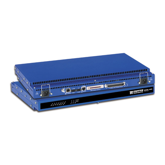
- Page 1 Model 3095 mDSL Digital Access and Cross- Connect System (DACS) Administrator’s Reference Guide Sales Office: +1 (301) 975-1000 +1 (301) 975-1007 Technical Support: E-mail: support@patton.com WWW: www.patton.com Document Number: 110062U Rev. A Part Number: O7MD3095-ARG-A Revised: November 26, 2001...
- Page 2 Patton Electronics Company, Inc. 7622 Rickenbacker Drive Gaithersburg, MD 20879 USA Voice: +1 (301) 975-1000 Fax: +1 (301) 869-9293 Technical Support: +1 (301) 975-1007 Technical Support e-mail: support@patton.com WWW: www.patton.com Copyright © 2001, Patton Electronics Company. All rights reserved. The information in this document is subject to change without notice. Patton Electronics assumes no liability for errors that may appear in this document.
-
Page 3: Table Of Contents
Contents About this guide ..............................15 Audience................................15 Structure................................15 Typographical conventions used in this document....................16 General conventions ............................16 Mouse conventions ............................17 1 Introduction ..............................19 Introduction ................................20 Logging into the HTTP/HTML Administration Pages ..................20 HTTP/HTML and SNMP Object Format ......................20 Saving HTTP/HTML Object Changes .........................21 2 Home................................ - Page 4 Contents mDSL DACS Administrators’ Reference Guide Displaying the alarms window ..........................40 Alarm Response Outputs ..........................42 Relay Response (alarmRlay(1)) ........................42 Minor Alarm SYSLOG Priority (minorSyslogPriority) ................42 Major Alarm SYSLOG Priority (majorSyslogPriority) ................42 Minor Alarm SNMP Trap IP [address] (minorTrapIp) ................42 Major Alarm SNMP Trap IP [address] (majorTrapIp) ................42 Temperature Threshold (boxAlarmTemperature) ..................42 Current Box Temperature (boxTemperature) ....................42 Clear All Alarms ............................42...
- Page 5 mDSL DACS Administrators’ Reference Guide Contents Clock Status (daxClockFailure) ........................58 9 mDSL Port Configuration ..........................59 Introduction ................................61 mDSL Port Configuration window ........................61 Action buttons ..............................62 mDSL Port Table ............................63 Port Number (mdslconfigID) .........................63 Circuit ID (userIDMdsl) ..........................63 DSP Status (dspStateMdsl) ..........................64 Desired State (userDesireMdsl) ........................64 The Test Mode Selection (testModeMdsl) ......................65 Loopback tests ............................65...
- Page 6 Contents mDSL DACS Administrators’ Reference Guide Port Alarm Information ..........................77 Line Down Alarm Severity (lineDownSeverityMdsl) .................77 Bit Error Alarm Severity (bitErrSeverityMdsl) ...................77 Alarm Thresholds ............................77 Errored Seconds Alarm Threshold (errSecThresholdMdsl) ..............77 Severely Errored Seconds Alarm Threshold (sevErrSecThresholdMdsl) ..........77 Unavailable Seconds Alarm Threshold (unavailSecThresholdMdsl).............
- Page 7 mDSL DACS Administrators’ Reference Guide Contents Received Frames Too Long (dot3StatsFrameTooLongs) .................87 Other Received Errors (dot3StatsInternalMacReceiveErrors) ................88 Chip Set ID (dot3StatsEtherChipSet) ......................88 11 Filter IP ................................. 89 Introduction ................................90 Defining a filter ..............................90 Name (filterIpName) ............................92 Direction (filterIpDirection) ...........................92 Action (filterIpAction) ............................92 Source IP (filterIpSourceIp) ..........................92 Source IP Mask (filterIpSourceMask) ......................92 Destination IP (filterIpDestinationIp) ......................92...
- Page 8 Contents mDSL DACS Administrators’ Reference Guide Forwarding (ipForwarding) ...........................104 Default Time-To-Live (ipDefaultTTL) ......................104 Total Datagrams Received (ipInReceives) .....................104 Discarded for Header Errors (ipInHdrErrors) ....................104 Discarded for Address Errors (ipInAddrErrors) .....................104 Forwarded Datagrams (ipForwDatagrams) ....................104 Discarded for Unknown Protos (ipInUnknownProtos) .................104 Discarded w/No Errors (ipInDiscards) ......................104 Total Deliveries (ipInDelivers) ........................105 Out Requests (ipOutRequests) ........................105...
- Page 9 mDSL DACS Administrators’ Reference Guide Contents Type (ipRouteType) .............................111 Protocol (ipRouteProto) ..........................111 Info (ipRouteInfo) ............................111 IP Routing Destination window ..........................112 Route Destination (genRouteDest) .......................112 Mask (genRouteMask) ..........................112 Interface (genRouteIfIndex) ..........................112 Protocol (genRouteProto) ..........................112 Seconds Since Updated (genRouteAge) ......................113 Tag (genRouteTag) ............................113 Gateway (genRouteGateway) ........................113 Cost (genRouteCost) ............................113 State (genRouteState) ............................113...
- Page 10 Contents mDSL DACS Administrators’ Reference Guide Received With No Ports (udpNoPorts) ......................122 Others Received with No Delivery (udpInErrors) ..................122 Sent (udpOutDatagrams) ..........................122 Listener Table (udpTable) ..........................122 Local Address (udpLocalAddress) ........................122 Local Port (udpLocalPort) ..........................123 17 RIP Version 2 .............................. 125 Introduction ................................126 RIP Version 2 main window..........................126 Route Changes Made (rip2GlobalRouteChanges) ..................126...
- Page 11 mDSL DACS Administrators’ Reference Guide Contents Get Requests (snmpInGetRequests) ......................133 Get Next Requests (snmpInGetNexts) ......................134 Set Requests (snmpInSetRequests) ........................134 Get Responses (snmpInGetResponses) ......................134 Traps (snmpInTraps) ............................134 Out ..................................134 Out Packets (snmpOutPkts) .........................134 Error Status “Too Big” (snmpOutTooBigs) ....................134 No Such Names (snmpOutNoSuchNames) ....................134 Bad Values (snmpOutBadValues) .........................134 Generated Errors (snmpOutGenErrs) ......................134 Get Requests (snmpOutGetRequests) ......................134...
- Page 12 Contents mDSL DACS Administrators’ Reference Guide Total Size (boxHeapSize) ........................142 Free (boxHeapFreeSpace) ........................142 Largest (boxHeapLargestSpace) .......................142 Enclosure System ............................142 Internal Temperature (boxTemperature) ....................142 Highest Temperature (boxMaxTemperature) ..................142 Installation ..............................142 Country (installCountry) ........................142 Other ................................142 Total DRAM Detected (boxDetectedMemory) ..................142 SystemID (sysObjectID) .........................142 Running Since Last Boot (sysUpTime) ....................143 System Manager (sysContact) ........................143 Box Name (sysName) ..........................143...
- Page 13 mDSL DACS Administrators’ Reference Guide Contents Introduction ................................150 System Log Main Window ..........................150 System Log—Modify ............................151 Daemons ..............................151 SysLog Daemon IP Address(syslogDaemonIP) ..................151 SNMP Trap Daemon IP Address (syslogTrapIP) ..................151 Priority .................................151 Min Priority for SysLog Daemon (syslogDaemonPriority) ..............152 Min Priority for Console RS-232 (syslogConsolePriority) ...............152 Min Priority for Flash Storage (syslogFlashPriority) ................152 Min Priority for SNMP Trap Daemon (syslogTrapPriority) ..............152 Min Priority for RAM (SyslogTablePriority) ...................153...
- Page 14 Contents mDSL DACS Administrators’ Reference Guide Circuit ID (dsx1CircuitIdentifier) ......................165 Line Type (dsx1LineType) Type (dsx1LineType) ..................166 Line Coding (dsx1LineCoding) .......................166 Receive Equalizer (linkRxEqualizer) ......................166 Line Build Out (linkLineBuildOut) ......................166 Yellow Alarm Format (linkYellowFormat) ....................167 FDL (dsx1FDL) ............................167 Test Settings ..............................167 Force Yellow Alarm (linkYellowForce) ....................167 Loopback Configuration (dsx1LoopbackConfig) ..................167 Send Code (dsx1SendCode) ........................168...
- Page 15 mDSL DACS Administrators’ Reference Guide Contents Line Errored Seconds (dsx1TotalLESs) ......................172 Bursty ErroredSeconds (dsx1TotalBESs) .......................172 Degraded Minutes (dsx1TotalDMs) ......................173 Line Code Violations (dsx1TotalLCVs) ......................173 Far End Line Statistics—Current.........................173 Time Elapsed (dsx1FarEndTimeElapsed) ......................173 Errored Seconds (dsx1FarEndCurrentESs) ....................173 Severely Errored Seconds (dsx1FarEnd CurrentSESs) ...................173 Severely Errored Frame Seconds (dsx1FarEndCurrentSEFSs) ...............173 Unavailable Seconds (dsx1FarEndCurrentUASs) ..................173 Controlled Slip Seconds (dsx1FarEndCurrentCSSs) ..................174...
- Page 16 Contents mDSL DACS Administrators’ Reference Guide Slot # (daxWANxDeviceSlot) where x is a number from 1 to 31..............182 23 About................................183 Introduction ................................184 Patton Electronics Company contact information ....................184 24 License................................. 185 Introduction ................................186 End User License Agreement ..........................186 1.
-
Page 17: About This Guide
About this guide This guide describes configuring a Patton Electronics Digital Access and Cross-Connect System (DACS). This section describes the following: • Who should use this guide (see “Audience”) • How this document is organized (see “Structure”) • Typographical conventions and terms used in this guide (see “Typographical conventions used in this docu- ment”... -
Page 18: Typographical Conventions Used In This Document
About this guide mDSL DACS Administrators’ Reference Guide • Chapter 17 describes using the RIP Version 2 window • Chapter 18 describes using the SNMP window • Chapter 19 describes using the System window • Chapter 20 describes using the System Log window •... -
Page 19: Mouse Conventions
mDSL DACS Administrators’ Reference Guide About this guide Mouse conventions The following conventions are used when describing mouse actions: Table 2. Mouse conventions Convention Meaning Left mouse button This button refers to the primary or leftmost mouse button (unless you have changed the default configuration). - Page 20 About this guide mDSL DACS Administrators’ Reference Guide...
-
Page 21: Introduction
Introduction Chapter 1 Chapter contents Introduction ................................20 Logging into the HTTP/HTML Administration Pages ..................20 HTTP/HTML and SNMP Object Format ......................20 Saving HTTP/HTML Object Changes .........................21... -
Page 22: Introduction
1 • Introduction mDSL DACS Administrators’ Reference Guide Introduction You may configure the Digital Access and Cross-Connect System (DACS) by using its internal HTTP/HTML Administration Pages. However, to enter into the HTTP/HTML pages, you must first define the LAN Address Technique, LAN IP Address, and LAN Subnet Mask for the DACS. -
Page 23: Saving Http/Html Object Changes
mDSL DACS Administrators’ Reference Guide 1 • Introduction Saving HTTP/HTML Object Changes Sometimes you will need to save changes that you have made in the HTTP/HTML pages. Do the following to make changes to read/write variables: 1. Select the appropriate Modify screen. - Page 24 1 • Introduction mDSL DACS Administrators’ Reference Guide Saving HTTP/HTML Object Changes...
-
Page 25: Home
Chapter 2 Home Chapter contents Introduction ................................24 Operating Status Variables ............................25 Egress Card Installed (boxEgressType) ......................25 Number of Egress Ports (boxEgressCount) .....................25 % CPU Idle (boxIdleTime) ..........................25 Running Since Last Boot (sysUpTime) ......................25 Total System Alarms (alarmTotal) ........................25 Immediate Actions ..............................26 Record Current Configuration (storeConfig(1)) .....................26 Hard Reset (hardReset(2)) ..........................26 Set Factory Default Configuration (forceDefaultConfig(3)) ................26... -
Page 26: Introduction
2 • Home mDSL DACS Administrators’ Reference Guide Introduction HOME Administration Page This chapter describes the window—the first that you see after logging into the HOME DACS (see figure 3). From , you can monitor current systems status, save any system configuration changes, or reset the system without power-cycling the DACS. -
Page 27: Operating Status Variables
% CPU Idle (boxIdleTime) This is an indication of the amount of system CPU power which is not being utilized by the Model 3095. The returned value is a percentage of free CPU cycles since the last time the variable was read. -
Page 28: Immediate Actions
2 • Home mDSL DACS Administrators’ Reference Guide Immediate Actions There are several immediate actions (see figure 5) in superuser mode which will cause the DACS to operate according to the descriptions in the following sections. Figure 5. Immediate Actions buttons Record Current Configuration (storeConfig(1)) This feature saves the current configuration in permanent FLASH memory. -
Page 29: Import/Export
Import/Export Chapter 3 Chapter contents Introduction ................................28 Export Configuration ............................28 Import Configuration............................30... -
Page 30: Introduction
3 • Import/Export mDSL DACS Administrators’ Reference Guide Introduction The Import/Export function enables you to make a backup (or export) copy of your DACS’s configuration parameters. By exporting the configurations, the saved files can quickly be loaded, or imported, into a replace- ment DACS—greatly speeding up the installation process should an DACS need replacing. - Page 31 mDSL DACS Administrators’ Reference Guide 3 • Import/Export To export the flash configuration, click on the Export Flash link on the Import/Export main page. The DACS will display text configuration information resembling that shown in figure 7. Figure 7. Typical DACS flash memory configuration data Export Configuration...
-
Page 32: Import Configuration
3 • Import/Export mDSL DACS Administrators’ Reference Guide To save the displayed data as a text file, select the option on your browser (see figure 8). For example, Save under Netscape, select . A dialog box will display enabling you to save the contents of the export >... -
Page 33: System Status
Chapter 4 System Status Chapter contents Introduction ................................32 Refresh Rate ................................32 System Status parameters............................33 Navigating the WAN Port Information parameters ..................33 Navigating the mDSL Port Information parameters ..................34... -
Page 34: Introduction
4 • System Status mDSL DACS Administrators’ Reference Guide Introduction The System Status window (see figure 9) displays a comprehensive status summary of the major Model 3095 subsystems. The web page is divided into the following parameter groupings: • System Status—Displays the state of Alarms, the internal temperature of the 3095, the current operational status of the two power supplies and the 3095’s system clock. -
Page 35: System Status Parameters
mDSL DACS Administrators’ Reference Guide 4 • System Status • rate15sec(15)—Refresh every 15 seconds • rate30sec(30)—Refresh every 30 seconds • rate1min(60)—Refresh every minute (60 seconds) • rate2min(120)—Refresh every 2 minutes (120 seconds) • rate3min(180)—Refresh every 3 minutes (180 seconds) • rate5min(300)—Refresh every 5 minutes (300 seconds) Click Submit Query after selecting the desired refresh rate. -
Page 36: Navigating The Mdsl Port Information Parameters
4 • System Status mDSL DACS Administrators’ Reference Guide • Status—Shows the condition of the WAN circuit. The WAN Port status color indicators show the state of each mDSL port.The different symbols are defined as follows. • Green square: Functioning properly and no alarms are present. •... -
Page 37: System History
Chapter 5 System History Chapter contents Introduction ................................36 WAN Port Information table ..........................36 mDSL History table ..............................37... -
Page 38: Introduction
5 • System History mDSL DACS Administrators’ Reference Guide Introduction System History window (see figure 10) provides quick access to the configuration parameters and statisti- cal data for all WAN circuits and mDSL ports. It contains the following tables: • WAN Port Information—... -
Page 39: Mdsl History Table
mDSL DACS Administrators’ Reference Guide 5 • System History mDSL History table The mDSL table contains the following information: • Port—Clicking on this link displays the mDSL Port Information Page window for reviewing or configuring the mDSL port. • Circuit ID—This is the name of an mDSL circuit •... - Page 40 5 • System History mDSL DACS Administrators’ Reference Guide mDSL History table...
-
Page 41: Alarms
Chapter 6 Alarms Chapter contents Introduction ................................40 Displaying the alarms window ..........................40 Alarm Response Outputs ..........................42 Relay Response (alarmRlay(1)) ........................42 Minor Alarm SYSLOG Priority (minorSyslogPriority) ................42 Major Alarm SYSLOG Priority (majorSyslogPriority) ................42 Minor Alarm SNMP Trap IP [address] (minorTrapIp) ................42 Major Alarm SNMP Trap IP [address] (majorTrapIp) ................42 Temperature Threshold (boxAlarmTemperature) ..................42 Current Box Temperature (boxTemperature) ....................42... -
Page 42: Introduction
6 • Alarms mDSL DACS Administrators’ Reference Guide Introduction The DACS has an extensive alarm reporting system which enables users to configure, monitor, and test major and minor alarms. The alarm system can be set to notify of equipment failures (for example, a power supply failure) or T1/E1 port malfunctions. - Page 43 mDSL DACS Administrators’ Reference Guide 6 • Alarms The mDSL Multiplexer has four methods to notify an alarm condition: 1. Front panel LED—The front panel ALARM LED has three states that indicate the presence and severity of an alarm. The states are: Off—No alarm present Solid—Minor alarm Flashing—Major alarm.
-
Page 44: Alarm Response Outputs
6 • Alarms mDSL DACS Administrators’ Reference Guide clearing, or major self-clearing alarm. Any alarm type may be disabled. (“Modify Alarms—Configuring alarm severity levels” on page 46) Alarm Response Outputs Alarm Response Outputs display the current setting for handling alarm notification via the different Alarm Response Outputs. -
Page 45: Alarm Name (Alarmname)
mDSL DACS Administrators’ Reference Guide 6 • Alarms Alarm Name (alarmName) The alarm items are grouped into two categories: system and WAN trunk alarms. The system group category lists DACS temperature and power supply status. The WAN category monitors the T1/E1 ports for yellow and red alarms. -
Page 46: Alarm Parameters
6 • Alarms mDSL DACS Administrators’ Reference Guide Figure 13. Alarm Response System window Alarm Parameters The Alarm Status Table on the Alarm System main page displays the current alarm status. You may also manu- ally generate an alarm as a test and clear the alarm, the alarm time and the alarm count variables. •... -
Page 47: Modify Response-Configuring The Alarm Response System
mDSL DACS Administrators’ Reference Guide 6 • Alarms WAN 1–16: Red Alarm—When a WAN port sends a red alarm, the specific WAN alarm will be sent. • mDSL Alarm Group mDSL 1–16: Line Down—When an mDSL modem line is down, an alarm is generated. mDSL 1–16: Bit Error—When the bit error for an mDSL modem connection exceeds a particular value, an alarm is generated. -
Page 48: Modify Alarms-Configuring Alarm Severity Levels
6 • Alarms mDSL DACS Administrators’ Reference Guide Modify Alarms—Configuring alarm severity levels Modify Alarms Clicking on window (see figure 14) displays a table listing each individual alarm. From this page you can configure the severity for each alarm (such as major, minor, major self-clearing, and minor self- clearing). - Page 49 mDSL DACS Administrators’ Reference Guide 6 • Alarms ated. If the alarm condition has ceased, the alarm will be automatically cleared after the same fixed period of time. • MajorSelfClearing(4)—Same as MinorSelfClearing(3) except that it is a Major alarm instead of Minor. Note For maximum application flexibility, the administrator shall choose which constitute major or minor alarm.
- Page 50 6 • Alarms mDSL DACS Administrators’ Reference Guide Modify Alarms—Configuring alarm severity levels...
-
Page 51: Ds0 Mapping
DS0 Mapping Chapter 7 Chapter contents Introduction ................................50 Displaying the DS0 Mapping window........................50 DACS Display Type ............................50 Help (DACS help information) ........................51 Static Connection ............................51 ID (daxConnectionID) ..........................51 Device Type (daxDeviceTypeTomDSL) (daxDeviceTypeFrommDSL) .............51 Device Number (daxDeviceNumberTomDSL) (daxDeviceNumberFrommDSL) ........51 Device Slots (daxDeviceSlotTo) (daxDeviceSlotFrom) ................52 Configuration ..............................52... -
Page 52: Introduction
7 • DS0 Mapping mDSL DACS Administrators’ Reference Guide Introduction One of the remote locations is the CPE’s mDSL modem. The second remote location is typically connected through some WAN port’s time slots. For communication between these remote locations they shall be con- nected together within the DACS. -
Page 53: Help (Dacs Help Information)
Port 3 (referring to mDSL modem #3), then select "Port 3" in the "Device Num- ber" field. Note that there are 16 t1-e1 ports. Since there are either 8 or 16 mDSL modems within the 3095, you may choose any of the 8 or 16 ports. -
Page 54: Device Slots (Daxdeviceslotto) (Daxdeviceslotfrom)
7 • DS0 Mapping mDSL DACS Administrators’ Reference Guide Device Slots (daxDeviceSlotTo) (daxDeviceSlotFrom) The “slots” input identifies the DS0 channels—each DS0 channel is 64 kbps—that you would like to connect. Each mDSL modem has up to 31 DS0 channels. Each time slot in a T1 or E1 WAN port has 24 or 31 DS0 channels, respectively. - Page 55 mDSL DACS Administrators’ Reference Guide 7 • DS0 Mapping Example #2: To connect a T1 line, (WAN) Port 2, timeslots 4 – 6, to another T1 line, (WAN) Port 3, timeslots 8 – 10, input the following string: t1-e1:2:4 – 6/t1-e1:3:8-10 Example #3: To connect two mDSL modems together, such as mDSL modem #6, timeslots 1 –...
- Page 56 7 • DS0 Mapping mDSL DACS Administrators’ Reference Guide Displaying the DS0 Mapping window...
-
Page 57: System Clocking
Chapter 8 System Clocking Chapter contents Introduction ................................56 Configuring the System Clock Settings........................56 Main Reference (daxClockMainRef) .......................56 Fallback Reference (daxClockFallbackRef) ......................57 Clock Status (daxClockFailure) ........................58... -
Page 58: Introduction
8 • System Clocking mDSL DACS Administrators’ Reference Guide Introduction Clocking System Clocking Configuration Click on in the Configuration Menu to display the main window (see figure 17). Figure 17. System Clocking Configuration window The Clocking window is where the primary and secondary clocking sources that synchronize all DS0 channels are configured. -
Page 59: Fallback Reference (Daxclockfallbackref)
• external(300)—The external clock source connected to the 3-position terminal block on the rear of the Model 3095 is the clock source. Fallback Reference (daxClockFallbackRef) The fallback reference enables the configuration of a back-up clock reference should the main reference fail. -
Page 60: Clock Status (Daxclockfailure)
8 • System Clocking mDSL DACS Administrators’ Reference Guide Clock Status (daxClockFailure) The clock status indicates alarm conditions relating to the system clock. If there are no alarms, the Clocking page will indicate No Alarm (see figure 17 on page 56). If an alarm condition exists, an Alarms Present message will be displayed along with one of the following failure descriptions. -
Page 61: Mdsl Port Configuration
Chapter 9 mDSL Port Configuration Chapter contents Introduction ................................61 mDSL Port Configuration window ........................61 Action buttons ..............................62 mDSL Port Table ............................63 Port Number (mdslconfigID) .........................63 Circuit ID (userIDMdsl) ..........................63 DSP Status (dspStateMdsl) ..........................64 Desired State (userDesireMdsl) ........................64 The Test Mode Selection (testModeMdsl) ......................65 Loopback tests ............................65 DTE Rate (dteRateMdsl) ..........................66 Clock Mode (clockModeMdsl) ........................66... - Page 62 9 • mDSL Port Configuration mDSL DACS Administrators’ Reference Guide Remote Unit TX Edge (Remote Status) (remoteTXEdgeMdsl) ..............76 Set Factory Default Configuration button ....................76 Port Alarm Information ..........................77 Line Down Alarm Severity (lineDownSeverityMdsl) .................77 Bit Error Alarm Severity (bitErrSeverityMdsl) ...................77 Alarm Thresholds ............................77 Errored Seconds Alarm Threshold (errSecThresholdMdsl) ..............
-
Page 63: Introduction
They summarize information about the mDSL modem links between the 3095 and the CPE mDSL modems, also providing the ability to configure certain of the mDSL parameters. The information may be display-only fields or user-entry fields. -
Page 64: Action Buttons
Activate Ports 13 - 16 will activate the mDSL modems in the appropriate group. • If your Model 3095 has 8 modems, only Activate Ports 1 - 4 and Activate Ports 5 - 8 buttons will dis- play. mDSL Port Configuration window... -
Page 65: Mdsl Port Table
As with all Submit Query entries, the configuration changes are saved in volatile dynamic memory. After HOME clicking on Submit Query, the changes take effect immediately. Only by going to the page in the 3095 Configuration Menu Save Current Configuration and clicking on will the configuration be stored in non-volatile Flash memory. -
Page 66: Dsp Status (Dspstatemdsl)
Figure 19. Loopbacks diagram DSP Status (dspStateMdsl) Shows the current status of the mDSL modems inside the 3095. The different states are: • idle(0)—disconnected • dataLink(1)—indicates that the "DSP" modules in the mDSL modems have established communication •... -
Page 67: The Test Mode Selection (Testmodemdsl)
) loops the data originating from the CPE remote modem through lineLoopoBack(9) the AFE of the 3095's internal modem. Except for the local loopback initiated by the CPE remote modem, all loopback tests are initiated and con- trolled by the 3095 DACS. -
Page 68: Dte Rate (Dteratemdsl)
When the end-user at the CPE remote modem location initiates a local loopback test on the modem, there are two possible paths: • If there is a data connection between the remote modem and the 3095's internal modem, the path is looped back through the framer. •... - Page 69 External—clock is derived from the mDSL time slot exchangers • Receive—the clock source is recovered from the DSL line. When the 3095 is equipped with a T1/E1 egress card, the clock mode would be one of the following: • ext-receiveClock(1) •...
-
Page 70: Mdsl Port Information Window
9 • mDSL Port Configuration mDSL DACS Administrators’ Reference Guide mDSL Port Information window mDSL Port Configuration mDSL Port Infor- Clicking on port number link in the table displays the selected port’s mation Page window (see figure 20). Figure 20. mDSL Port Information Page window, part 1 mDSL Port Information window... -
Page 71: Mdsl Port X (Where X Can Be Any Mdsl Port From 1 To 16.)
mDSL DACS Administrators’ Reference Guide 9 • mDSL Port Configuration Figure 21. mDSL Port Information Page window, part 2 mDSL Port 1 Port Runtime Statisti- The page is divided into groups named (this is an example for Modem #1), cal Information Port Configuration Information Port Alarm Information Port... -
Page 72: Mdsl Port Desired State (Userdesiremdsl)
Click Submit Query after selecting the desired test mode state. Port Runtime Statistical Information Dsp State (dspStateMdsl) This item shows the current status of the of the mDSL modem internal to the 3095. The different states are: • idle(0)—disconnected •... -
Page 73: Line (S/N Ratio) Quality (Db) (Linequalitymdsl)
DACS Administrators’ Reference Guide 9 • mDSL Port Configuration • hardwareFailure(200)—indicates that this particular mDSL modem in the 3095 has failed and is not oper- ational The following describes the normal sequence of states an mDSL modem goes through during the connection process: 1. -
Page 74: Dsl Flap Counter (Flapcountermdsl)
The total number of times in which the mDSL modem circuit has gone down and back up. A modem link is down when it is not in the dataSync state. If this number becomes high, it is indicating that something is affecting the quality of the circuit connection between the mDSL modem in the 3095 and the CPE’s remote modem. -
Page 75: Line Rate (Local Status) And (Remote Status) (Lineratemdsl)
mDSL DACS Administrators’ Reference Guide 9 • mDSL Port Configuration Line Rate (Local Status) and (Remote Status) (lineRateMdsl) This is the line rate of the mDSL modem link. It is always higher than the DTE rate, that is, the data rate of the connection. -
Page 76: Dte Rate (Local Status) (Dteratemdsl)
This setting is configured automatically by the DACS. Framer Mode (Remote Status) (remoteframerModeMdsl) The Model 3095 will read the remote modem’s Framer Mode. Normally you will not configure this parameter from the 3095. The states for the remote modem are: •... -
Page 77: Co/Cp Mode (Local Status) (Cocpmodemdsl)
CO refers to the Central Office or central site where the 3095 is located. CP is the customer’s premises. For the mDSL modems to function, one modem must be in CO and the other in CP mode. Normally the 3095’s internal modem is configured for CO mode. -
Page 78: Unit User Id (Local Status) (Useridmdsl)
If enabled(0), the remote modem is able to initiate a local Loopback via the DTE interface. If disabled(1), it cannot. The notavailable(50) parameter normally appears when the 3095’s modem is in the idle state or if there is no line connection between the modems. -
Page 79: Port Alarm Information
mDSL DACS Administrators’ Reference Guide 9 • mDSL Port Configuration Port Alarm Information Line Down Alarm Severity (lineDownSeverityMdsl) Configures the severity of the alarm when the modem line is down. The options are: • ignore(0) • minor(1) • major(2) • minorSelfClearing(3) •... -
Page 80: Port Error Statistics
Once the port gains link status, the 3095 begins looking for ES and SES. • Upon receiving 10 consecutive SES or a line down indication, the 3095 will begin reporting UAS. The 3095 will not increment ES or SES during the UAS count. -
Page 81: Mdsl Port X (Mdslintervalindex)
Once the port is activated and a link-up timer has expired, the UAS counter will be incremented if the ports loses sync or does not enter synchronization with the far end of the link. • Once the port gains link status, the 3095 begins looking for ES and SES. mDSL Port Information window... -
Page 82: Line Quality (Historylinequalitymdsl)
9 • mDSL Port Configuration mDSL DACS Administrators’ Reference Guide • A line down indication, the 3095 will begin reporting UAS. The 3095 will not increment ES or SES during the UAS count. Line Quality (historyLineQualityMdsl) Displays the signal quality of the mDSL link for each of the 15 minute intervals. It is measured as the S/N ratio in dB. -
Page 83: Mdsl Port Configuration Page Window
mDSL DACS Administrators’ Reference Guide 9 • mDSL Port Configuration mDSL Port Configuration Page window mDSL Port Configuration mDSL Clicking on any hyperlink port number in the table goes to the selected port's Port Information Page window. To configure the mDSL modem port, go to “Configuration State (changeParamMdsl)”... -
Page 84: Dte Rate (Dteratemdsl)
CO refers to the Central Office or central site where the 3095 is located. CP is the customer’s premises. For the mDSL modems to function, one modem must be in CO and the other in CP mode. Normally the 3095’s internal modem is configured for CO mode. -
Page 85: Remote Unit User Id (Remoteuseridmdsl)
If enabled(0), the remote modem is able to initiate a local Loopback via the DTE interface. If disabled(1), it cannot. The notavailable(50) parameter normally appears when the 3095’s modem is in the idle state or if there is no line connection between the modems. -
Page 86: Configuration State (Changeparammdsl)
The normal(1) mode indicates the remote modem’s CO/CP parameter was automatically configured by the 3095. In other words, the CO/CP mode is determined by which clock mode the CPE modem is in. When forcetoCP(0) appears, the 3095’s user sent the configuration option to the remote modem to force it to be CP or the remote modem was independently preconfigured to CP mode. -
Page 87: Ethernet
Chapter 10 Ethernet Chapter contents Introduction ................................86 Ethernet statistics..............................86 Alignment Errors (dot3StatsAlignmentErrors) ....................86 FCS Errors (dot3StatsFCSErrors) ........................86 Single Collision Frames (dot3StatsSingleCollision Frames) ................86 Multiple Collision Frames (dot3StatsMultipleCollisionFrames) ..............87 SQE Test Errors (dot3StatsSQETestErrors) ....................87 Deferred Transmissions (dot3StatsDeferredTransmissions) ................87 Late Collisions (dot3StatsLateCollisions) ......................87 Excessive Collisions (dot3StatsExcessiveCollisions) ..................87 Other Errors (dot3StatsInternalMacTransmitErrors) ..................87 Carrier Sense Errors (dot3StatsCarrierSenseErrors) ..................87... -
Page 88: Introduction
10 • Ethernet mDSL DACS Administrators’ Reference Guide Introduction Ethernet The DACS provides management and statistical information in the window (see figure 24). Most of the descriptions for these MIB variables are from RFC 1643. Detailed information regarding the SNMP MIB II variables may be downloaded from RFC 1643, Definitions of Managed Objects for the Ethernet-like Interface Types. -
Page 89: Multiple Collision Frames (Dot3Statsmultiplecollisionframes)
mDSL DACS Administrators’ Reference Guide 10 • Ethernet castPkts, ifOutMulticastPkts, or ifOutBroadcastPkts, and is not counted by the corresponding instance of the dot3StatsMultipleCollisionFrames object." Multiple Collision Frames (dot3StatsMultipleCollisionFrames) The number of successfully transmitted frames for which transmission is inhibited by more than one collision. A frame that is counted by an instance of this object is also counted by the corresponding instance of either the ifOutUcastPkts, ifOutMulticastPkts, or ifOutBroadcastPkts, and is not counted by the corresponding instance of the dot3StatsSingleCollisionFrames object."... -
Page 90: Other Received Errors (Dot3Statsinternalmacreceiveerrors)
10 • Ethernet mDSL DACS Administrators’ Reference Guide Other Received Errors (dot3StatsInternalMacReceiveErrors) The number of frames in which reception fails due to an internal MAC sublayer receive error. A frame is only counted if it is not counted by either the dot3StatsFrameTooLongs object, the dot3StatsAlignmentErrors object, or the dot3StatsFCSErrors object. -
Page 91: Filter Ip
Chapter 11 Filter IP Chapter contents Introduction ................................90 Defining a filter ..............................90 Name (filterIpName) ............................92 Direction (filterIpDirection) ...........................92 Action (filterIpAction) ............................92 Source IP (filterIpSourceIp) ..........................92 Source IP Mask (filterIpSourceMask) ......................92 Destination IP (filterIpDestinationIp) ......................92 Destination Mask (filterIpDestinationMask) ....................93 Source Port (FilterIpSourcePort) ........................93 Action (filterIpSourcePortCmp) ........................93 Destination Port (filterIpDestinationPort) ......................93 Action (filterIpDestinationPortCmp) ......................93... -
Page 92: Introduction
The DACS enables 20 separate filters to be defined, of which up to 10 can be used during a single user connec- tion. Since the IP connections in the 3095 are only for the superuser and the monitor user, these will be the only two users. - Page 93 mDSL DACS Administrators’ Reference Guide 11 • Filter IP After entering an ID number (filterIpId) and a name (filterIpName), click on the name of the filter to display the filter parameters window (see figure 26). Figure 26. Filter IP parameters window The configurable filter parameters are : •...
-
Page 94: Name (Filteripname)
11 • Filter IP mDSL DACS Administrators’ Reference Guide The following sections provide detailed descriptions of the configurable filter IP parameters. Name (filterIpName) This is the name of the filter Direction (filterIpDirection) Specifies the direction of the filter (that is, whether it applies to data packets inbound or outbound from the DACS). -
Page 95: Destination Mask (Filteripdestinationmask)
mDSL DACS Administrators’ Reference Guide 11 • Filter IP Destination Mask (filterIpDestinationMask) This is the destination mask used when comparing a packet’s destination address. Bit positions that are set to 1 will be compared and 0’s will be ignored. Thus, a setting of 0.0.0.0 will have the effect of disabling destination IP address comparison. - Page 96 11 • Filter IP mDSL DACS Administrators’ Reference Guide Defining a filter...
-
Page 97: Frame Relay
Chapter 12 Frame Relay Chapter contents Introduction ................................96... -
Page 98: Introduction
12 • Frame Relay mDSL DACS Administrators’ Reference Guide Introduction The Frame Relay feature is not currently implemented. Introduction... -
Page 99: Icmp
ICMP Chapter 13 Chapter contents Introduction ................................98 Block ICMP redirects (boxBlockIcmpRedirects)....................98 ICMP Receive/Send Messages window........................98 Total Received (icmpInMsgs) .........................98 Total Sent [imcpOutMsgs] ..........................99 w/Errors (icmpInErrors, icmpOutErrors) ......................99 Destinations Unreachable (IcmpInDestUnreachs, IcmpOutDestUnreachs) ............99 Times Exceeded (icmpInTimeExcds, icmpOutTimeExcds) ................99 Parameter Problems (icmpInParmProbs, icmpOutParmProbs) ...............99 Source Quenchs (icmpInSrcQuenchs, icmpOutSrcQuenchs) .................99 Redirects (icmpInRedirects, icmpOutRedirects) ...................100 Echos (icmpInEchos, icmpOutEchos) ......................100... -
Page 100: Introduction
Both gateways (routers) and hosts can send ICMP messages. Total Received (icmpInMsgs) The total number of ICMP messages which the 3095 Multiplexer has received. Note that this counter includes all those counted by icmpInErrors (see “w/Errors (icmpInErrors, icmpOutErrors)” on page 99). -
Page 101: Total Sent [Imcpoutmsgs]
DACS Administrators’ Reference Guide 13 • ICMP Total Sent [imcpOutMsgs] Similar to icmpInMsgs, Total Sent represents the total number of ICMP messages which the 3095 has attempted to send. This variable includes all ICMP messages counted by icmpOutErrors (see “w/Errors (icmp- InErrors, icmpOutErrors)”). -
Page 102: Redirects (Icmpinredirects, Icmpoutredirects)
13 • ICMP mDSL DACS Administrators’ Reference Guide Redirects (icmpInRedirects, icmpOutRedirects) The number of ICMP redirect messages received/sent. A gateway sends a redirect message to a host if the net- work gateways find a shorter route to the destination through another gateway. Echos (icmpInEchos, icmpOutEchos) The number of ICMP echo request messages received/send. - Page 103 Chapter 14 Chapter contents Introduction ................................103 IP main window ..............................103 Forwarding (ipForwarding) ...........................104 Default Time-To-Live (ipDefaultTTL) ......................104 Total Datagrams Received (ipInReceives) .....................104 Discarded for Header Errors (ipInHdrErrors) ....................104 Discarded for Address Errors (ipInAddrErrors) .....................104 Forwarded Datagrams (ipForwDatagrams) ....................104 Discarded for Unknown Protos (ipInUnknownProtos) .................104 Discarded w/No Errors (ipInDiscards) ......................104 Total Deliveries (ipInDelivers) ........................105 Out Requests (ipOutRequests) ........................105...
- Page 104 14 • IP mDSL DACS Administrators’ Reference Guide Add a route: ..............................110 Advanced… ..............................110 O/S forwarding table window..........................110 Destination (ipRouteDest) ..........................110 Mask (ipRouteMask) ............................110 Next Hop (ipRouteNextHop) ........................110 Interface (ipRouteIfIndex) ..........................111 Type (ipRouteType) .............................111 Protocol (ipRouteProto) ..........................111 Info (ipRouteInfo) ............................111 IP Routing Destination window ..........................112 Route Destination (genRouteDest) .......................112 Mask (genRouteMask) ..........................112...
-
Page 105: Introduction
mDSL DACS Administrators’ Reference Guide 14 • IP Introduction The IP (Internet Protocol) window lists IP statistics and parameters, and enables you to modify IP settings. Figure 28. IP main window Configuration Menu Click on under the to display the window. -
Page 106: Forwarding (Ipforwarding)
14 • IP mDSL DACS Administrators’ Reference Guide Forwarding (ipForwarding) The indication of whether this entity is acting as an IP gateway in respect to the forwarding of datagrams received by, but not addressed to, this entity. IP gateways forward datagrams, IP hosts do not (except those source-routed via the host). -
Page 107: Total Deliveries (Ipindelivers)
mDSL DACS Administrators’ Reference Guide 14 • IP Note The Discarded w/No Errors counter does not include any datagrams discarded while awaiting re-assembly. Total Deliveries (ipInDelivers) The total number of input datagrams successfully delivered to IP user-protocols (including ICMP). Out Requests (ipOutRequests) The total number of IP datagrams which local IP user-protocols (including ICMP) supplied to IP in requests for transmission. -
Page 108: Fragmented Ok (Ipfragoks)
14 • IP mDSL DACS Administrators’ Reference Guide # Fragmented OK (ipFragOKs) The number of IP datagrams that have been successfully fragmented at this entity. # Fragmented Failed (ipFragFails) The number of IP datagrams that have been discarded because they required fragmenting at this entity, but were not fragmented because their Don’t Fragment option was set. -
Page 109: Addressing Information
mDSL DACS Administrators’ Reference Guide 14 • IP Addressing Information The IP addressing Information (ipAdEntAddr) window (see figure 30) is where you can view the default address for outgoing IP datagrams, the local or loopback address of the box, and the IP address of the box as defined in Chapter 19, “System”. -
Page 110: Routing Information
14 • IP mDSL DACS Administrators’ Reference Guide Routing Information The IP Routing Information window (see figure 32) displays information required to route IP datagrams, including the IP address, subnet mask, next-hop router, and interface for each network interface defined in the DACS. -
Page 111: Mask (Genroutemask)
mDSL DACS Administrators’ Reference Guide 14 • IP Mask (genRouteMask) Indicates the mask to be logical-ANDed with the destination address before being compared to the value in the ipRouteDest field. For those systems that do not support arbitrary subnet masks, an agent constructs the value of the ipRouteMask by determining whether the value of the corresponding ipRouteDest field belongs to a Class A, B, or C network, and then using the appropriate mask from table 6. -
Page 112: Add A Route
14 • IP mDSL DACS Administrators’ Reference Guide Add a route: This portion of the IP Routing Information window is where you can add a new route to the IP Routing Infor- mation table. Fill in the Destination (genRouteDest) Mask (genRouteMask) , and Gateway (genRouteGate- way) -
Page 113: Interface (Iprouteifindex)
mDSL DACS Administrators’ Reference Guide 14 • IP Interface (ipRouteIfIndex) The index value that identifies the local interface through which the next hop of this route should be reached. The interface identified by a particular value of this index is the same interface as identified by the same value of ifIndex. -
Page 114: Ip Routing Destination Window
14 • IP mDSL DACS Administrators’ Reference Guide IP Routing Destination window The IP Routing Destination window (see figure 34) shows next-hop routing information. Figure 34. Routing Destination window Route Destination (genRouteDest) The destination IP address of this route. An entry with a value of 0.0.0.0 is considered a default route. Multiple routes to a single destination can appear in the table, but access to such multiple entries is dependent on the table-access mechanisms defined by the network management protocol in use. -
Page 115: Seconds Since Updated (Genrouteage)
mDSL DACS Administrators’ Reference Guide 14 • IP Seconds Since Updated (genRouteAge) The number of seconds since this route was last updated or otherwise determined to be correct. Tag (genRouteTag) An identifier associated with the route. This can have different meanings depending on the protocol. For exam- ple, this gives the tag that was passed with a learned RIP route. -
Page 116: Net Address (Ipnettomedianetaddress)
14 • IP mDSL DACS Administrators’ Reference Guide Net Address (ipNetToMediaNetAddress) The IP address corresponding to the media-dependent physical address. Physical (ipNetToMediaPhysAddress) The media-dependent physical address. Type (ipNetToMediaType) The type of mapping. Setting this object to the value invalid(2) has the effect of invalidating the corresponding entry in the ipNetToMediaTable. -
Page 117: Tcp
Chapter 15 Chapter contents Introduction ................................116 TCP main window ..............................116 Retransmit-Timeout Algorithm (tcpRtoAlgorithm) ..................116 Retransmit-Timeout Minimum (tcpRtoMin) ....................116 Retransmit-Timeout Maximum (tcpRtoMax) ....................116 Maximum Connections (tcpMaxConn) ......................117 Active Opens (tcpActiveOpens) ........................117 Passive Opens (tcpPassiveOpens) ........................117 Attempt/Fails (tcpAttemptFails) ........................117 ESTABLISHED Resets (tcpEstabResets) ......................117 Current ESTABLISHED (tcpCurrEstab) .....................117 Total Received (tcpInSegs) ..........................117 Total Sent (tcpOutSegs) ..........................117... -
Page 118: Introduction
Transmission Control Protocol (TCP) is in the Transport layer of the OSI model and sits on top of IP. It is one of the more widely used protocols among the TCP/IP suite. The TCP subsystem web pages of the 3095 DACS provides management and statistical information on TCP. -
Page 119: Maximum Connections (Tcpmaxconn)
mDSL DACS Administrators’ Reference Guide 15 • TCP Maximum Connections (tcpMaxConn) The limit on the total number of TCP connections the entity can support. In entities where the maximum number of connections is dynamic, this object should contain the value -1. Active Opens (tcpActiveOpens) The number of times TCP connections have made a direct transition to the SYN-SENT state from the CLOSED state. -
Page 120: Tcp (Details)
15 • TCP mDSL DACS Administrators’ Reference Guide TCP (Details) From this screen you can view port details for remote and local TCP connections (see figure 37). Figure 37. TCP Details window Local Port (tcpConnLocalPort) The local port number for this TCP connection. Remote Address (tcpConnRemAddress) The remote IP address for this TCP connection. - Page 121 mDSL DACS Administrators’ Reference Guide 15 • TCP • finWait1(6) • finWait2(7) • closeWait(8) • lastAck(9) • closing(10) • timeWait(11) • deleteTCB(12)—The only value which may be set by a management station. TCP (Details)
- Page 122 15 • TCP mDSL DACS Administrators’ Reference Guide TCP (Details)
-
Page 123: Udp
Chapter 16 Chapter contents Introduction ................................122 Received (udpInDatagrams) ..........................122 Received With No Ports (udpNoPorts) ......................122 Others Received with No Delivery (udpInErrors) ..................122 Sent (udpOutDatagrams) ..........................122 Listener Table (udpTable) ..........................122 Local Address (udpLocalAddress) ........................122 Local Port (udpLocalPort) ..........................123... -
Page 124: Introduction
16 • UDP mDSL DACS Administrators’ Reference Guide Introduction User Datagram Protocol (UDP) is supported by the DACS. Detailed information regarding the SNMP man- agement information base (MIB) variables can be found in RFC1213: Management Information Base for Net- work Management of TCP/IP-based internets: MIB-II. Configuration Menu To manage and collect statistics on UDP, click on under the... -
Page 125: Local Port (Udplocalport)
mDSL DACS Administrators’ Reference Guide 16 • UDP Local Port (udpLocalPort) The local port number for this UDP listener. Introduction... - Page 126 16 • UDP mDSL DACS Administrators’ Reference Guide Introduction...
-
Page 127: Rip Version 2
Chapter 17 RIP Version 2 Chapter contents Introduction ................................126 RIP Version 2 main window..........................126 Route Changes Made (rip2GlobalRouteChanges) ..................126 Responses Sent (rip2GlobalQueries) ......................126 Adding a RIP address ............................126 RIP Version 2—Configuration..........................127 Address (rip2IfConfAddress) .........................127 Domain (rip2IfConfDomain) ........................128 Authentication Type (rip2IfConfAuthType) ....................128 Authentication Key (rip2IfConfAuthKey) .....................128 Send (rip2IfConfSend) ..........................128 Receive (rip2IfConfReceive) .........................128... -
Page 128: Introduction
1. Enter the IP network address of the interface on the 3095 DACS that you want to enable RIP. This will be the LAN IP address, in other words, the IP address of the 3095. This is not the IP address of the device you want to direct RIP packets to. -
Page 129: Rip Version 2-Configuration
mDSL DACS Administrators’ Reference Guide 17 • RIP Version 2 2. Enter the protocol version to be used for sending RIP packets. The following choices are available: – doNotSend (1) – —ripVersion 1 implies sending RIP updates compliant with RFC 1058 ripVersion1 (2) –... -
Page 130: Domain (Rip2Ifconfdomain)
17 • RIP Version 2 mDSL DACS Administrators’ Reference Guide Domain (rip2IfConfDomain) Routing Domain Value inserted into the field of all RIP packets sent on this interface. Authentication Type (rip2IfConfAuthType) The type of Authentication used on this interface. • noAuthentication (1) •... -
Page 131: Status (Rip2Ifconfstatus)
mDSL DACS Administrators’ Reference Guide 17 • RIP Version 2 Status (rip2IfConfStatus) Writing invalid has the effect of deleting this interface. • valid (1) • invalid (2) RIP Version 2 (Statistics) By clicking on Statistics in the RIP Version 2 main window, you enter the RIP Version 2 Status window (see... - Page 132 17 • RIP Version 2 mDSL DACS Administrators’ Reference Guide RIP Version 2 (Statistics)
-
Page 133: Snmp
Chapter 18 SNMP Chapter contents Introduction ................................132 SNMP window..............................132 In ..................................132 Packets (snmpInPkts) ............................132 Bad Version (snmpInBadVersions) .......................132 Bad Community Names (snmpInBadCommunityNames) ................133 Bad Community Uses (snmpInBadCommunity) ..................133 ASN ParseErrors (snmpInASNParseErrs) ......................133 Error Status “Too Big” (snmpInTooBigs) .....................133 No Such Names (snmpInNoSuchNames) .....................133 Bad Values (snmpInBadValues) ........................133 Error Status “Read Only”... -
Page 134: Introduction
18 • SNMP mDSL DACS Administrators’ Reference Guide Introduction The DACS provides management and statistical information on SNMP. Detailed information on the SNMP SNMP Configuration Menu MIB variables may be downloaded from the RFC. Click on under the to dis- play the SNMP window (see figure 42). -
Page 135: Bad Community Names (Snmpinbadcommunitynames)
mDSL DACS Administrators’ Reference Guide 18 • SNMP Bad Community Names (snmpInBadCommunityNames) The total number of SNMP Messages delivered to the SNMP protocol entity which used a SNMP community name not known to said entity. Bad Community Uses (snmpInBadCommunity) The total number of SNMP messages delivered to the SNMP protocol entity which represented an SNMP operation which was not allowed by the SNMP community named in the message. -
Page 136: Get Next Requests (Snmpingetnexts)
18 • SNMP mDSL DACS Administrators’ Reference Guide Get Next Requests (snmpInGetNexts) The total number of SNMP Get-Next PDUs that have been accepted and processed by the SNMP protocol entity. Set Requests (snmpInSetRequests) The total number of SNMP Set-Request PDUs that have been accepted and processed by the SNMP protocol entity. -
Page 137: Get Responses (Snmpoutgetresponses)
Immediate Actions ing on Record Current Configuration under on the Home page of the 3095 DACS. If the network management system is re-initialized (implying power cycling) while assuming the current configuration has been recorded, the current configuration will not be lost. - Page 138 18 • SNMP mDSL DACS Administrators’ Reference Guide...
-
Page 139: System
Chapter 19 System Chapter contents Introduction ................................139 System main window............................140 CPU ................................140 Percentage CPU Idle (boxIdletime) ......................140 Time Slices Fully Utilized (boxCPUcritical) ....................140 Time Slices 90% Utilized (boxCPUWarning) ..................140 SNMP and HTTP ............................140 Version (boxSnmpVersion) ........................140 Super User Password (boxSnmpMasterPassword) ..................140 User Password (boxSnmpMonitorPassword) ...................140 LAN IP .................................140 How to Obtain Address (boxIPAddressTechnique) .................141... - Page 140 19 • System mDSL DACS Administrators’ Reference Guide Physical Location (sysLocation) .......................143 Web Settings (boxBackgroundFlag) ......................143 Monitor Privilege (boxMonitorPrivilege) ....................143 System—Modify window ............................144 SNMP and HTTP ............................144 Version (boxSnmpVersion) ........................144 Superuser Password (boxSnmpMasterPassword) ..................144 Superuser Password Verification (boxSnmpVerifyMasterPassword) ............144 User Password (boxSnmpMonitorPassword) ...................145 User Password Verification (boxSnmpVerifyPassword) ................145 LAN IP .................................145 Method to Obtain Address (boxIPAddressTechnique) ................145...
-
Page 141: Introduction
mDSL DACS Administrators’ Reference Guide 19 • System Introduction System main window (see figure 43) contains general setup information about the DACS. System param- eters are Patton Enterprise MIB object identifiers, though some are contained in RFC 1213, Management System Con- Information Base for Network Management of TCP/IP-based internets: MIB-II. -
Page 142: System Main Window
19 • System mDSL DACS Administrators’ Reference Guide System main window From this window you can view information for the CPU, SNMP and HTTP, LAN IP, Manufacturer, Message Blocks, Operating System Heap Memory, Enclosure System, Installation, and Other. The main window also has the following links: Modify •... -
Page 143: How To Obtain Address (Boxipaddresstechnique)
mDSL DACS Administrators’ Reference Guide 19 • System How to Obtain Address (boxIPAddressTechnique) This displays the current method for obtaining the LAN IP address (see figure 43 on page 139). Address(boxIPAddress) Address If the address technique in use above is static, then the value displayed in the field is the LAN IP address (see figure 43 on page 139). -
Page 144: Total Times Unavailable (Boxcountmsgblkunavailable)
19 • System mDSL DACS Administrators’ Reference Guide Total Times Unavailable (boxCountMsgBlkUnavailable) The total number of times that the proper size message block was not available to hold a packet, and the CPU task dumped the packet. The difference between Total Time Waited Total Times Unavailable is whether the... -
Page 145: Running Since Last Boot (Sysuptime)
mDSL DACS Administrators’ Reference Guide 19 • System Running Since Last Boot (sysUpTime) This SNMP variable represents the time since the network management portion of the system was last re-ini- tialized (see figure 43 on page 139). System Manager (sysContact) This SNMP variable represents the textual identification of the contact person for this managed node, which may include information on how to contact this person as defined by specification RFC1213.MIB (see figure 43 on page 139). -
Page 146: System-Modify Window
19 • System mDSL DACS Administrators’ Reference Guide System—Modify window System—Modify window (see figure 44) is where you can change SNMP and HTTP, LAN IP, Installation, and Other. Figure 44. System—Modify window SNMP and HTTP System—Modify This portion of the window provides information about the SNMP version and the HTTP accessibility. -
Page 147: User Password (Boxsnmpmonitorpassword)
mDSL DACS Administrators’ Reference Guide 19 • System User Password (boxSnmpMonitorPassword) This accesses the user monitoring password for read only access of certain selected information. Not all param- eters shown using the superuser password are displayed under the user password. (see figure 44 on page 144). User Password Verification (boxSnmpVerifyPassword) This is verification for the password. -
Page 148: Other
19 • System mDSL DACS Administrators’ Reference Guide • canada(3) • europeanUnion(4) • france(5) • germany(6) Other This portion of the System—Modify window contains information described in the following sections. System Manager (sysContact) This SNMP variable represents the textual identification of the contact person for this managed node, together with information on how to contact this person as defined by specification RFC1213.MIB. -
Page 149: System-Packet Holding Message Blocks
mDSL DACS Administrators’ Reference Guide 19 • System • writeUserlpWanSystemUpload(498)—The monitor user can change all parameters—except passwords— under authentication, drop-and-insert, dial-in, IP, T1/E1, Frame Relay, System, and System Log links. The monitor user can also load firmware updates into the DACS. System—Packet Holding Message Blocks... - Page 150 19 • System mDSL DACS Administrators’ Reference Guide System—Packet Holding Message Blocks...
-
Page 151: System Log
System Log Chapter 20 Chapter contents Introduction ................................150 System Log Main Window ..........................150 System Log—Modify ............................151 Daemons ..............................151 SysLog Daemon IP Address(syslogDaemonIP) ..................151 SNMP Trap Daemon IP Address (syslogTrapIP) ..................151 Priority .................................151 Min Priority for SysLog Daemon (syslogDaemonPriority) ..............152 Min Priority for Console RS-232 (syslogConsolePriority) ...............152 Min Priority for Flash Storage (syslogFlashPriority) ................152 Min Priority for SNMP Trap Daemon (syslogTrapPriority) ..............152 Min Priority for RAM (SyslogTablePriority) ...................153... -
Page 152: Introduction
20 • System Log mDSL DACS Administrators’ Reference Guide Introduction System Log window (see figure 46) displays the results from the system-wide error reporting subsystem. The object parameters in the system log are all Patton Enterprise MIB object identifiers. Figure 46. System Log main window System Log Main Window Besides displaying the results from the system-wide error reporting utility, the System Log... -
Page 153: System Log-Modify
mDSL DACS Administrators’ Reference Guide 20 • System Log System Log—Modify System Log—Modify SysLog SNMP Trap Daemon IP Address window (see figure 47) displays loca- tions, message priorities for the offered SysLog destinations, priority and maintenance information. Figure 47. System Log—Modify window Daemons System Log—Modify This portion of the... -
Page 154: Min Priority For Syslog Daemon (Syslogdaemonpriority)
System messages which have a priority equal to or greater than this setting will be sent directly to the RS-232 Config Port on the rear of the 3095. Messages will be sent regardless of the current operating state of the RS- 232 configuration port. -
Page 155: Min Priority For Ram (Syslogtablepriority)
mDSL DACS Administrators’ Reference Guide 20 • System Log • prioritySystem(80) • priorityDisable(1000) Min Priority for RAM (SyslogTablePriority) System messages which have a priority equal to or greater than this setting will appear in System Log—Volatile Memory. The lower the number next to the priority listed below, the more details system logging will provide. will generate the most messages, while will turn off all messages. -
Page 156: Call Trace (Syslogcalltrace)
To empty the flash memory, see option syslogFlashClear(2). • syslogFlashClear(2)—Erase system messages stored in Flash. Be sure to return to the 3095’s Home page and click on Record Current Configuration to store this change in permanent memory. System Log—Modify... -
Page 157: System Log-Volatile Memory
Figure 48. System Log—Volatile Memory window Time (slTick) Time stamps are generated every 10 ms. Message (slMessage) This is the message stored in RAM. If the 3095 DACS loses power, the messages in RAM will be lost. System Log—Volatile Memory... -
Page 158: System Log-Non-Volatile Memory
Figure 49. System Log—Non-Volatile Memory window Time (slfTick) Time stamps are generated every 10 ms. Message (slfMessage) This is the message stored in Flash memory. If the 3095 DACS loses power, the messages will not be lost. System Log—Non-Volatile Memory... -
Page 159: T1/E1 Link
Chapter 21 T1/E1 Link Chapter contents Introduction ................................160 T1/E1 Link Activity Ports main window ......................161 Link (dsx1LineIndex) ............................161 Type (dsx1LineType) ............................162 Circuit ID (dsx1CircuitIdentifier) .........................162 Line Status (dsx1LineStatus)..........................162 Failure States ..............................162 Far End Alarm Failure ..........................162 Alarm Indication Signal (AIS) Failure .....................163 Loss Of Frame Failure ..........................163 Loss Of Signal Failure ..........................163 Loopback Pseudo-Failure ........................163... - Page 160 21 • T1/E1 Link mDSL DACS Administrators’ Reference Guide Controlled Slip Seconds (dsx1CurrentCSSs) ....................169 Path Code Violations (dsx1CurrentPCVs) ....................169 Line Errored Seconds (dsx1CurrentLESs) .....................169 Bursty ErroredSeconds (dsx1CurrentBESs) ....................169 Degraded Minutes (dsx1CurrentDMs) ......................170 Line Code Violations (dsx1CurrentLCVs) ....................170 Near End Line Statistics—History........................170 Interval (dsx1IntervalNumber) ........................170 Errored Seconds (dsx1intervaless) ........................170 Severely Errored Seconds (dsx1IntervalSESs) ....................170...
- Page 161 mDSL DACS Administrators’ Reference Guide 21 • T1/E1 Link Severely Errored Frame Seconds (dsx1FarEndIntervalSEFSs) ................175 Unavailable Seconds (dsx1FarEndIntervalUASs) ...................175 Controlled Slip Seconds (dsx1FarEndIntervalCSSs) ..................175 Line Errored Seconds (dsx1FarEndIntervalLESs) ..................175 Path Code Violations (dsx1FarEndIntervalPCVs) ..................175 Bursty Errored Seconds (dsx1FarEndIntervalBESs) ..................175 Degraded Minutes (dsx1FarEndIntervalDMs) ....................175 Far End Line Statistics—Totals ...........................176 Errored Seconds (dsx1FarEndTotalESs) ......................176 Severly Errored Seconds (dsx1FarEndTotalSESs) ..................176...
-
Page 162: Introduction
RFC 1406 – Definitions of Managed Objects for the DS1 and E1 Interface Types. Figure 50. T1/E1 Link Activity Overview window /E1 Link 3095 Configuration Menu Click on T1 in the to display the T1/E1 Link Activity Overview main window. -
Page 163: T1/E1 Link Activity Ports Main Window
mDSL DACS Administrators’ Reference Guide 21 • T1/E1 Link • If an alarm or alarms are present for a specific WAN port, a hyperlink in red beside Line Status: will state Alarms Present. The associated web page called Circuit ID # Line Status Alarms points out the indication for the type of alarm. -
Page 164: Type (Dsx1Linetype)
21 • T1/E1 Link mDSL DACS Administrators’ Reference Guide Type (dsx1LineType) This variable indicates the type of DS1 line using the circuit. The circuit type determines the bits-per-second rate that the circuit can carry and how it interprets error statistics. The values are as follows: •... -
Page 165: Alarm Indication Signal (Ais) Failure
mDSL DACS Administrators’ Reference Guide 21 • T1/E1 Link For D4 links, the Far End Alarm failure occurs when bit 6 of all channels has been zero for at least 335 ms. The alarm is cleared when bit 6 of at least one channel is non-zero for a period T, where T is usually less than 1 sec- ond and always less than 5 seconds. -
Page 166: Far End Loss Of Multiframe Failure
21 • T1/E1 Link mDSL DACS Administrators’ Reference Guide Far End Loss Of Multiframe Failure The Far End Loss Of Multiframe failure is declared when bit 2 of TS16 of frame 0 is received set to one on two consecutive occasions. The Far End Loss Of Multiframe failure is cleared when bit 2 of TS16 of frame 0 is received set to zero. -
Page 167: Valid Intervals (Dsx1Validintervals)
mDSL DACS Administrators’ Reference Guide 21 • T1/E1 Link Valid Intervals (dsx1ValidIntervals) The number of previous intervals for which valid data was collected. The value will be 96 unless the interface was brought on-line within the last 24-hours, in which case the value will be the number of completed 15- minute intervals since the interface has been online. -
Page 168: Line Type (Dsx1Linetype) Type (Dsx1Linetype)
21 • T1/E1 Link mDSL DACS Administrators’ Reference Guide Line Type (dsx1LineType) Type (dsx1LineType) This variable indicates the type of DS1 Line implemented on this circuit. The type of circuit affects the num- ber of bits per second that the circuit can reasonably carry, as well as the interpretation of the usage and error statistics. -
Page 169: Yellow Alarm Format (Linkyellowformat)
mDSL DACS Administrators’ Reference Guide 21 • T1/E1 Link • t1pulse-7dB(3)—Medium pulse amplitude. • t1pulse-15dB(4)—Weak pulse amplitude. Yellow Alarm Format (linkYellowFormat) This variable identifies which standard will be used to transmit and identify the Yellow Alarm. • link YellowFormatBit2(1)—Bit-2 equal zero in every channel •... -
Page 170: Send Code (Dsx1Sendcode)
• injectCRCerrorBurst(1) • injectLineErrorBurst(2) Yellow Alarm Severity () This reference is identical to the reference on the Alarms page in the 3095 Configuration Menu . The configu- Alarms ration may be changed here or in the page. • ignore(0) •... -
Page 171: Near End Line Statistics-Current
mDSL DACS Administrators’ Reference Guide 21 • T1/E1 Link Near End Line Statistics—Current Near End Line Statistics—Current Click on to display line statistics for the current 15-minute interval (see figure 55). Figure 55. Current Near End Performance window Errored Seconds (dsx1CurrentESs) The number of errored seconds, encountered by a DS1 interface in the current 15-minute interval. -
Page 172: Degraded Minutes (Dsx1Currentdms)
A number between 1 and 96, where 1 is the most recently completed 15-minute interval and 96 is the least recently completed 15-minutes interval. When all 96 intervals are visible, then the 3095 has been operating (powered-on) for at least 24 hours. If less than 96 intervals are visible, then it has been less than 24 hours since the 3095 was powered up. -
Page 173: Severely Errored Frame Seconds (Dsx1Intervalsefss)
mDSL DACS Administrators’ Reference Guide 21 • T1/E1 Link Severely Errored Frame Seconds (dsx1IntervalSEFSs) The number of severely errored framing seconds encountered by a DS1 interface in one of the previous 96, individual 15-minute, intervals. Unavailable Seconds (dsx1IntervalUASs) The number of unavailable seconds encountered by a DS1 interface in one of the previous 96, individual 15- minute, intervals. -
Page 174: Near End Line Statistics-Totals
21 • T1/E1 Link mDSL DACS Administrators’ Reference Guide Near End Line Statistics—Totals Near End Line Statistics—Totals Click on to display the total statistics of errors that occurred during the previ- ous 24-hour period, the previous 96 15-minute intervals (see figure 57). Figure 57. -
Page 175: Degraded Minutes (Dsx1Totaldms)
mDSL DACS Administrators’ Reference Guide 21 • T1/E1 Link Degraded Minutes (dsx1TotalDMs) The number of degraded minutes (DMs) encountered by a DS1 interface in the previous 24-hour interval. Line Code Violations (dsx1TotalLCVs) The number of line code violations (LCVs) encountered by a DS1 interface in the current 15-minute interval. Far End Line Statistics—Current Near End Line Statistics—Current Click on... -
Page 176: Controlled Slip Seconds (Dsx1Farendcurrentcsss)
21 • T1/E1 Link mDSL DACS Administrators’ Reference Guide Controlled Slip Seconds (dsx1FarEndCurrentCSSs) The number of far-end controlled slip seconds encountered by a DS1 interface in the current 15-minute inter- val. Line Errored Seconds (dsx1FarEndCurrentLESs) The number of far-end line errored seconds encountered by a DS1 interface in the current 15-minute interval Path Code Violations (dsx1FarEndCurrentPCVs) The number of far-end path coding violations reported via the far-end block error count encountered by a DS1 interface in the current 15-minute interval. -
Page 177: Interval (Dsx1Farendintervalnumber)
mDSL DACS Administrators’ Reference Guide 21 • T1/E1 Link Interval (dsx1FarEndIntervalNumber) A number between 1 and 96, where 1 is the most recently completed 15-minute interval and 96 is the least recently completed 15-minutes interval (assuming that all 96 intervals are valid). Errored Seconds (dsx1FarEndIntervalESs) The number of far-end errored seconds encountered by a DS1 interface in one of the previous 96, individual 15-minute, intervals. -
Page 178: Far End Line Statistics-Totals
21 • T1/E1 Link mDSL DACS Administrators’ Reference Guide Far End Line Statistics—Totals Far End Line Statistics—Totals Click on to display the total statistics of errors that occurred during the previous 24-hour period (see figure 60). This is the sum of the current 15-minute interval and all time prior intervals within the last 24 hours. -
Page 179: Bursty Errored Seconds (Dsx1Farendtotalbess)
mDSL DACS Administrators’ Reference Guide 21 • T1/E1 Link Bursty Errored Seconds (dsx1FarEndTotalBESs) The number of far-end bursty errored seconds (BESs) encountered by a DS1 interface in the previous 24-hour interval. Degraded Minutes (dsx1FarEndTotalDMs) The number of far-end degraded minutes (DMs) encountered by a DS1 interface in the previous 24-hour interval. - Page 180 21 • T1/E1 Link mDSL DACS Administrators’ Reference Guide Far End Line Statistics—Totals...
-
Page 181: T1/E1 Assignment
T1/E1 Assignment Chapter 22 Chapter contents Introduction ................................180 T1/E1 Assignment window (Mapping Overview)....................180 T1/E1 Assignment Tables ...........................181 Slot (daxWANConnectionID) ........................182 Device (daxWANxDeviceType) where x is a number from 0 to 15..............182 Port # (daxWANxDeviceNumber) where x is a number from 0 to 15............182 Slot # (daxWANxDeviceSlot) where x is a number from 1 to 31. -
Page 182: Introduction
22 • T1/E1 Assignment DSL DACS Administrators’ Reference Guide Introduction The T1/E1 Assignment section contains the DS0 mapping connections for each WAN port time slot. Click on T1/E1 Assignment Configuration Menu under the to display the T1/E1 Assignment window (mapping over- view) (see figure 61). -
Page 183: T1/E1 Assignment Tables
DSL DACS Administrators’ Reference Guide 22 • T1/E1 Assignment Figure 62. WAN Assignment Table window T1/E1 Assignment Tables Each WAN Assignment Table window (see figure 62) consists of four column groups, one for each WAN port in that particular group. The top of each column identifies the WAN port by name, e.g., “WAN Port 1” or “WAN Port 7.”... -
Page 184: Slot (Daxwanconnectionid)
22 • T1/E1 Assignment DSL DACS Administrators’ Reference Guide Figure 63. Circuit ID 1 Line Status Alarms window Under each WAN port column group are four columns nameed Slot, Device, Port #, and Slot #, which are defined in the following sections. Slot (daxWANConnectionID) Slot refers to the time slot in the T1/E1 port. -
Page 185: About
Chapter 23 About Chapter contents Introduction ................................184 Patton Electronics Company contact information ....................184... -
Page 186: Introduction
23 • About mDSL DACS Administrators’ Reference Guide Introduction About link displays Patton Electronics Company contact information (see “Patton Electronics Company About Configuration Menu About contact information”). Click on under the to display the main window (see figure 64). Figure 64. About window Patton Electronics Company contact information Patton Electronics Company 7622 Rickenbacker Drive... -
Page 187: License
Chapter 24 License Chapter contents Introduction ................................186 End User License Agreement ..........................186 1. Definitions: ...............................186 2. Title: .................................187 3. Term: ................................187 4. Grant of License: ............................187 5. Warranty: ..............................187 6. Termination: .............................187... -
Page 188: Introduction
24 • License mDSL DACS Administrators’ Reference Guide Introduction License License link presents the End User License Agreement for the DACS software. Click on under the Configuration Menu License to display the main window (see figure 65). Figure 65. License window By opening the DACS, operating the Designated Equipment or downloading the Program(s) electronically, the End User agrees to the conditions in the “End User License Agreement”... -
Page 189: Title
mDSL DACS Administrators’ Reference Guide 24 • License 2. Title: Title to the Program(s), all copies of the Program(s), all patent rights, copyrights, trade secrets and proprietary information in the Program(s), worldwide, remains with Patton Electronics Company or its licensors. 3. - Page 190 24 • License mDSL DACS Administrators’ Reference Guide End User License Agreement...
-
Page 191: A Network Ports (Rj-21X) Connector Pin-Out
Appendix A Network Ports (RJ-21X) connector pin-out Chapter contents Introduction ................................70... -
Page 192: Introduction
A • Network Ports (RJ-21X) connector pin-out mDSL DACS Administrators’ Reference Guide Introduction Table 7 contains the band-marked color codes for the RJ-21X, 50-pin Telco connector. The Pair Number matches the port number on the DS0 Mapping Management page. NETWORK PORTS Figure 66. - Page 193 mDSL DACS Administrators’ Reference Guide A • Network Ports (RJ-21X) connector pin-out Table 7. Band Marked Color Code (Continued) Wire/Color Code Tip and Ring Pair Number 50 Pin Positions Black/Slate Tip 15 Pair 15 Slate/Black Ring 15 Yellow/Blue Tip 16 Pair 16 Blue/Yellow Ring 16...
- Page 194 A • Network Ports (RJ-21X) connector pin-out mDSL DACS Administrators’ Reference Guide Introduction...
-
Page 195: B Wan Network Module Connector Pin-Out
Appendix B WAN Network Module connector pin-out Chapter contents Introduction ................................194... -
Page 196: Introduction
DSL DACS Administrators’ Reference Guide B • WAN Network Module connector pin-out Introduction Table 8 and Table 9 contain the pin-out information for the 68-pin SCSI connector. WAN NETWORK MODULE Figure 67. 68-pin SCSI connector Introduction... - Page 197 DSL DACS Administrators’ Reference Guide B • WAN Network Module connector pin-out Table 8. Pin-out information listed by pin number Description Description Port # Port # TX+_D TX+_J TX-_D TX-_J RX+_D RX+_J RX-_D RX-_J RX+_C RX+_I RX-_C RX-_I TX+_C TX+_I TX-_C TX-_I TX+_B...
- Page 198 DSL DACS Administrators’ Reference Guide B • WAN Network Module connector pin-out Table 9. Pin-out information listed by WAN port number Description Description Port # Port # TX+_A TX+_L TX-_A TX-_L RX+_A RX+_L RX-_A RX-_L TX+_B TX+_K TX-_B TX-_K RX+_B RX+_K RX-_B RX-_K...
- Page 199 DSL DACS Administrators’ Reference Guide B • WAN Network Module connector pin-out Introduction...
- Page 200 DSL DACS Administrators’ Reference Guide B • WAN Network Module connector pin-out Introduction...
Need help?
Do you have a question about the 3095 and is the answer not in the manual?
Questions and answers