Table of Contents
Advertisement
Quick Links
Advertisement
Table of Contents

Related Manuals for Owon ADS3000 Series


Summary of Contents for Owon ADS3000 Series
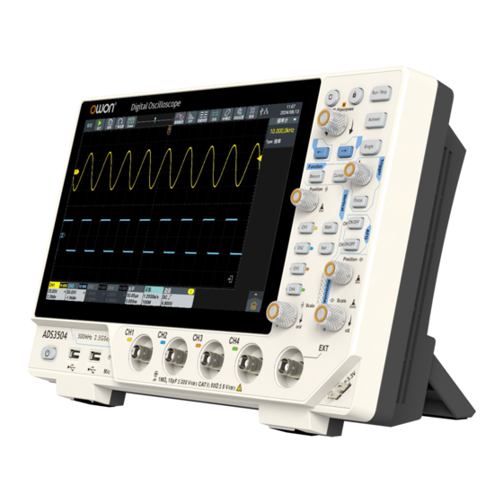
- Page 1 ADS3000 Series User Manual ADS3102/3104 ADS3202/3204 ADS3352/3354 ADS3502/3504 For product support, visit:www.owon.com.hk/download ※:The illustrations, interface, icons and characters in the user manual may be slightly different from the actual product. Please refer to the actual product.
- Page 2 LILLIPUT Company. Fujian LILLIPUT Optoelectronics Technology Co., Ltd. No. 19, Heming Road Lantian Industrial Zone, Zhangzhou 363005 P.R. China Tel: +86-596-2130430 Fax: +86-596-2109272 Web: E-mail: www.owon.com.cn info@owon.com.cn...
-
Page 3: General Warranty
General Warranty We warrant that the product will be free from defects in materials and workmanship for a period of 3 years from the date of purchase of the product by the original purchaser from our company. The warranty period for accessories such as probes is 12 months. -
Page 4: Table Of Contents
Table of Contents 1. General Safety Requirements ............1 2. Safety Terms And Symbols ..............3 How To Conduct A General Inspection .................5 How To Conduct Function Inspection ................... 6 3. Primary User Guide ................7 A General Knowledge Of The Structure Of The Instrument ..........8 Front Panel ........................8 Rear Panel ........................ - Page 5 How to Realize Waveform Operation Function ..........83 How To Set FFT ..................... 86 How To Set DIR(Digital Filtering) ................ 90 How To Set FRA (frequency response analysis) ..........92 How To Set Pass Fail .................... 94 How To Set Counter ....................96 How To Set DVM ....................98 How To Set Decode .....................101 How To Set Waveform Record/Player ............
- Page 6 Trigger ............................159 Trigger System ......................159 Trigger Type ........................160 Waveform ..........................161 Waveform Measurement .................... 161 Waveform Analysis ...................... 163 Decode ...........................163 Bode Plot ..........................164 AFG ............................164 Counter ..........................167 DVM ............................167 Command ..........................168 General Technical Specification ..................168 Display ...........................
-
Page 7: General Safety Requirements
1.General Safety Requirements General Safety Requirements Before use, please read the following safety precautions to avoid any possible bodily injury and to prevent this product or any other connected products from damage. In order to avoid any contingent danger, ensure this product is only used within the range specified. - Page 8 1.General Safety Requirements instrument. Avoid exposed circuit. Do not touch exposed junctions and components when the instrument is powered. Do not operate if in any doubt. If you suspect damage occurs to the instrument, have it inspected by qualified service personnel before further operations.
-
Page 9: Safety Terms And Symbols
2.Safety Terms And Symbols Safety Terms And Symbols Safety Terms Terms in this manual. The following terms may appear in this manual: Warning: Warning indicates the conditions or practices that could result in injury or loss of life. Caution: Caution indicates the conditions or practices that could result in damage to this product or other property. - Page 10 2.Safety Terms And Symbols To avoid body damage and prevent product and connected equipment damage, carefully read the following safety information before using the test tool. This product can only be used in the specified applications. Warning The four channels of the oscilloscope are not electrically isolated. The channels should adopt a common ground during measuring.
-
Page 11: How To Conduct A General Inspection
2.Safety Terms And Symbols Warning: To avoid fire or electrical shock, when the oscilloscope input signal connected is more than 42V peak (30Vrms) or on circuits of more than 4800VA, please take note of below items: Only use accessory insulated voltage probes and test lead. ... -
Page 12: How To Conduct Function Inspection
2.Safety Terms And Symbols 3. Check the Complete Instrument. If it is found that there is damage to the appearance of the instrument, or the instrument can not work normally, or fails in the performance test, please get in touch with our distributor responsible for this business or our local offices. -
Page 13: Primary User Guide
3.Primary User Guide Primary User Guide AFG is optional features. The corresponding AFG buttons/interfaces are only available on models that support these features. Please refer to the table below for details. In the following text, no further explanation will be provided; please refer to the specific model accordingly. -
Page 14: A General Knowledge Of The Structure Of The Instrument
3.Primary User Guide A General Knowledge Of The Structure Of The Instrument This chapter gives a brief description and introduction to the operations and functions of the front panel of the instrument, so as to facilitate your operations of the instrument in the shortest time. Front Panel On the instrument panel, knobs and function buttons are used to enter different function menus or directly use specific function application. -
Page 15: Arrow Keys
3.Primary User Guide turned to set the value. Example can rotate the knob to change the offset value. Arrow keys : Move to select the parameter. 3. Home key : Return to the main homepage. 4. Touch key : Press it to disable the touch screen, the key light turns on; and press it again to enable the touch screen, the key light turns off (Note: The Touch Lock is only available in EduInstr system and does not work on the main homepage and other application interface.). - Page 16 3.Primary User Guide Horizontal control area: Contain two knobs. “Horizontal Position” knob is to control the horizontal position triggered. “Horizontal Scale” knob is to control time base scale. 7. AFG control area: Contain two keys. “CH1 ON/OFF” key corresponds to enable/disable the AFG function; ...
-
Page 17: Rear Panel
3.Primary User Guide Rear Panel Figure 3-2: Rear Panel 1. Foldable Handle. 2. Heat Emission Hole. 3. USB-C power supply interface. 4. USB Host Interface: When the oscilloscope is connected to an external USB device as a “master device”, the USB Host interface is used to transmit the data. -
Page 18: A General Knowledge Of The User Interface Of The Instrument
3.Primary User Guide 9. Foot Rest: To adjust the inclined angle of the oscilloscope. 10.Fuse. 11.Power outlet. 12.Safety lock. 13.AFG CH2 port. 14.AFG CH1 port. A General Knowledge Of The User Interface Of The Instrument Figure 3-3:Illustrative Drawing of Display Interfaces 1. - Page 19 3.Primary User Guide 4. U disk access identifier. 5. System set time, click the icon will switch to the Date&time setting interface. 6. AFG, Counter and others function information display bar (Note: click on the left corner corresponds to enable/disable statistic). Right swipe the information display bar to close the corresponding function.
-
Page 20: How To Implement The Probe Compensation
3.Primary User Guide Oscilloscope Inspection 1. Set the Switch in the Oscilloscope Probe as 10X and Connect the Oscilloscope with CH1 Channel. Align the slot in the probe with the plug in the CH1 connector BNC, and then tighten the probe with rotating it to the right side. Connect the probe tip and the ground clamp to the connector of the probe compensator. -
Page 21: How To Set The Probe Attenuation Coefficient
3.Primary User Guide and connect the reference wire clamp with the ground wire connector of the probe connector, and then push the Autoset button on the front panel. 2. Check the displayed waveforms, see Figure 3-5. Regulate the probe till a correct compensation is achieved, see Figure 3-6. -
Page 22: How To Use The Probe Safely
3.Primary User Guide Make sure that the set value of the attenuation switch in the probe is the same as the menu selection of the probe attenuation coefficient in the oscilloscope. The set values of the probe switch are 1X and 10X,see Figure 3-7. Figure 3-7: Attenuation Switch Caution: When the attenuation switch is set to 1X, the probe will limit the... - Page 23 3.Primary User Guide optimum condition to obtain the most accurate measurement. This program can be performed at any time. It is especially necessary when the ambient temperature reaches or exceeds 5℃. To conduct self-calibration, disconnect all probes and wires from the input connector.
-
Page 24: Use The Android System
4.Use the Android System Use the Android System Android System Homepage Window 1. Application shortcut key. If you click the oscilloscope shortcut key, you can enter the oscilloscope interface. 2. App Drawer (Click to see all apps). 3. Task key. 4. - Page 25 4.Use the Android System...
-
Page 26: Use The Oscilloscope
5.Use the Oscilloscope Use the Oscilloscope A General Knowledge Of Oscilloscope A General Knowledge Of Trigger System As shown in Figure , there are one knob and one key. The following exercises are to guide you through the use of the trigger system. Figure 5-1: Trigger control area 1. -
Page 27: A General Knowledge Of Horizontal System
5.Use the Oscilloscope 2. Press CH2 ON/OFF key to enable/disable the CH2 AFG function. Open the key light on, close the key light off. A General Knowledge Of Horizontal System As shown in Figure ,there are two knobs. The following exercises to guide you through the use of the horizontal system. - Page 28 5.Use the Oscilloscope Figure 5-4: Vertical control area 1. Vertical Position knob to control the vertical display position of the signal. When turning the Vertical Position knob, the pointer indicating the Grounding Reference Point of the channel moves up and down following the waveform.
-
Page 29: How To Use Touch Screen Control
5.Use the Oscilloscope Turn the Vertical Scale knob to change the Vertical Scale Factor (Voltage Scale), and the scale factor of corresponding channel in the information display bar changes accordingly. 3. Press CH1、CH2、CH3、CH4 key to enable or disable the corresponding channel. - Page 30 5.Use the Oscilloscope Scroll List: When the scroll bar appears in the menu, swipe the screen up and down with the finger to scroll the list, as shown in the figure below. Open Main Menu: Click the icon in the lower right of the display area, the main menu window pops up, as shown below.
-
Page 31: Operate The Touch Screen
5.Use the Oscilloscope Operate The Touch Screen Select a Channel (CH1 channel, CH2 channel, CH3 channel or CH4 channel): Click the channel pointer on the left or click the channel waveform to make the channel pointer selected. Long press the channel pointer, the vertical position of waveform can be center. - Page 32 5.Use the Oscilloscope Set Horizontal Position (Horizontal Position knob): The horizontal position of the waveform can be changed by swiping your finger around the waveform display area, as shown in the figure below. The control voltage gear and time base can be scaled in the following way: ...
-
Page 33: Operate The Touch Screen In Waveform Amplification Mode
5.Use the Oscilloscope In the waveform display area, double-click the screen and slide the hand up and down/left and right to zoom the control voltage scale and time base. Operate The Touch Screen In Waveform Amplification Mode Press Horizontal Scale knob to enter the waveform zoom mode, the main window is displayed at the top half of the screen and the amplified window is displayed at the bottom half of the screen. -
Page 34: Other Touch Screen Operations
5.Use the Oscilloscope Other Touch Screen Operations Click and drag the open menu item to move itself to the appropriate location. - Page 35 5.Use the Oscilloscope Control the horizontal or vertical cursor lines under cursor measurement, as shown in the figure below. Run/Stop: Click in the upper left of the display area to switch Run/Stop. Parameter Setting Keyboard in Menu Item: There are digital input mode and hobbing input mode.
- Page 36 5.Use the Oscilloscope Swipe the information display bar...
-
Page 37: Advanced User Guide For Oscilloscope
5.Use the Oscilloscope Advanced User Guide for Oscilloscope In the previous chapter, basic operations of the oscilloscope, function area of the front panel and the roles of the keys and knobs are introduced for the user to determine the change of instrument settings by observing the status bar. -
Page 38: How To Set Vertical System
5.Use the Oscilloscope How To Set Vertical System In the vertical system control area, there are seven keys (CH1, CH2, CH3, CH4, Math and Ref) and two knobs (Vertical Position knob and Vertical Scale knob). Channel Settings Each channel is equipped with the independent vertical menu, and each item is set separately based on different channel. - Page 39 5.Use the Oscilloscope Pass the AC and DC component of the input signal. Coupling Block the DC component of the input signal. Ground Disconnect the input signal. Click to open or close the waveform Inverted inversion function. Click the Numeric Display Box and turn General knob or swipe the screen up and down in the numeric select box with the Common...
- Page 40 5.Use the Oscilloscope Center Based on the vertical center point of the screen, the waveform will be scaled around the vertical center point of the Expand oscilloscope screen. Offset Based on the vertical zero point of the channel, the waveform will be scaled around the channel's zero level.
- Page 41 5.Use the Oscilloscope ground potential. (1) Click the CH1 information display bar to bring up the CH1 Settings window. (2) Click Display switch in the menu to highlight it. (3) Click Inverted switch to highlight it, the waveform inversion will be enabled.
- Page 42 5.Use the Oscilloscope 6. Set bandwidth limit (1) Click the CH1 information display bar to bring up the CH1 Settings window. (2) Click Display switch in the menu to highlight it. (3) Select the oscilloscope bandwidth in the Limit option. ...
- Page 43 5.Use the Oscilloscope vertical zero point (zero level). 9. Set voltage scale (1) Click the CH1 information display bar to bring up the CH1 Settings window. (2) Click Display switch in the menu to highlight it. (3) Click the numeric box in the Scale option to display the scale select box.
-
Page 44: How To Set Horizontal System
5.Use the Oscilloscope Figure 5-4:Vertical information How To Set Horizontal System There are Horizontal Position knob and Horizontal Scale knob in the Horizontal System Control Area. 1. Horizontal Position knob: Adjust the horizontal position of all channels (including the mathematical operation), whose resolution changes with the time base. - Page 45 5.Use the Oscilloscope Horizontal expansion refers to the reference position on which the screen waveform is horizontally expanded or compressed when the horizontal time base is adjusted. This instrument supports horizontal extension data including centers and trigger points default to "centers". Expand Center Center: When changing the horizontal time base,...
-
Page 46: How To Set Acquire
5.Use the Oscilloscope the main window. In waveform amplification mode, the Horizontal Position knob and the Horizontal Scale knob are used to adjust the horizontal position and the horizontal time base of the amplified window. Navigate function (1)Click the bottom of screen Horizontal Information Display Bar, display horizontal setting window. -
Page 47: Setting Descriptions
5.Use the Oscilloscope The descriptions of setting window are shown in the table below: Menu Setting Descriptions Sample General Acquisition mode. Used to detect interference burrs and possibility of Peak reduce confusion. Reduce and improve the signal-to-noise ratio on Mode High Res aperiodic (single-shot) waveforms. -
Page 48: How To Set Trigger
5.Use the Oscilloscope at 1k. Additionally, when enabled, if the device is in pause mode, the horizontal position, time base, vertical position, voltage scale, and channel switching cannot be adjusted. Click , to select the length to be recorded 100k Depth on the right display box. -
Page 49: Trigger Control
5.Use the Oscilloscope There is one knob and one keys in the Trigger Control Area. Trigger Level: Turn this knob to set the signal voltage of corresponding trigger point and press this knob to make the trigger level at the vertical midpoint of the trigger signal amplitude. Forced Trigger: Generate a trigger signal forcibly, mainly used in the “Normal”... - Page 50 5.Use the Oscilloscope Set Channel 2 as the signal source trigger signal. Set Channel 3 as the signal source trigger signal. Set Channel 4 as the signal source trigger signal. Set the external trigger input channel as the signal source trigger signal. EXT/5 Set the external trigger source divided by 5 to extend the external trigger level range.
-
Page 51: Video Trigger
5.Use the Oscilloscope detected and then stop acquisition. Video Trigger Select the Video Trigger to trigger on standard video signal field or line of 525i/NTSC,625i/PAL or SECAM. Enter the video trigger and the trigger setting information is displayed in the lower part of the screen, such indicating that the video trigger is selected with the trigger information source of CH1 and synchronization type of line. -
Page 52: Pulse Trigger
5.Use the Oscilloscope or +) or turn the General knob to set the interval for restarting the trigger circuit, and click < > or press to move the cursor and select the digit to be set. 100ns Set the trigger hold-off time as 100ns. Auto Set to collect waveform even when no trigger condition is detected. -
Page 53: Slope Trigger
5.Use the Oscilloscope Click to set the pulse condition, click time setting’s Numeric Input Box to input the pulse width time to be set and click the unit to confirm; > or click Gear Input Box (- or +) or turn the =... - Page 54 5.Use the Oscilloscope below: Menu Settings Descriptions Set the trigger type of the vertical channel to Type Slope slope trigger. Set Channel 1 as the signal source trigger signal. Set Channel 2 as the signal source trigger signal. Source Set Channel 3 as the signal source trigger signal. Set Channel 4 as the signal source trigger signal.
-
Page 55: Runt Trigger
5.Use the Oscilloscope Auto Set to collect waveform even when no trigger condition is detected. Normal Set to collect waveform only when trigger Mode conditions are satisfied. Single Set to acquire a waveform when one trigger is detected and then stop acquisition. Runt Trigger Used to trigger a pulse that steps over one trigger level but not another. -
Page 56: Windows Trigger
5.Use the Oscilloscope Click to set the pulse width conditions, click Time setting time setting’s Numeric Input Box to input the pulse width to be set and click the unit to confirm; or click Gear Input Box (- or +) or turn General knob to set the pulse width, and click <... - Page 57 5.Use the Oscilloscope level.In Windows Trigger mode, the trigger setting information is displayed on bottom right of the screen, for example, ,indicates that trigger type is windows, trigger source is CH1, polarity is positive, 0.000pV the differential between up level and low level threshold. The descriptions of windows trigger setting window are shown in the table below: Menu...
-
Page 58: Timeout Trigger
5.Use the Oscilloscope 100ns – 10s; click Numeric Input Box to input the interval to be set for restarting the trigger circuit and click the unit to confirm; or click Gear Input Box (- or +) or turn the General knob to set HoldOff the interval for restarting the trigger circuit, and click <... -
Page 59: Nth Edge Trigger
5.Use the Oscilloscope Set the idle time. It refers to the minimum time that the clock signal must be in idle state before Idle Time the oscilloscope begins to search for data that meets the trigger conditions. The idle time ranges from 30ns to 10s with default value of 100ns. - Page 60 5.Use the Oscilloscope The descriptions of the Nth edge trigger setting window are shown in the table below: Menu Settings Descriptions Set vertical channel trigger type as Nth Edge Type Nth Edge trigger. Set Channel 1 as the signal source trigger signal. Set Channel 2 as the signal source trigger signal.
-
Page 61: Logic Trigger
5.Use the Oscilloscope Set the specific value of N in the Nth edge trigger. Click Numeric Input Box to input the edge number to be set and click OK to confirm; or click Gear Input Box (- or +) or turn the General knob to Edge Num set the edge number, and click <... - Page 62 5.Use the Oscilloscope below: Menu Settings Descriptions Type Logic Set vertical channel trigger type as Logic trigger. Set logic mode as AND. Logic Set logic mode as OR. Mode Set logic mode as XOR. Set logic mode as XNOR. XNOR Set CH1 as High Level, Low level, high or low level, Rise and Fall.
- Page 63 5.Use the Oscilloscope Click Numeric Display Box and turn General knob to set the CH1 Threshold. Click 50% and set the shortcut key of trigger level Threshold in the vertical midpoint of the trigger signal amplitude. Click Numeric Display Box and turn General knob to set the CH2 Threshold.
- Page 64 5.Use the Oscilloscope with the format as shown in the figure below. It is triggered when a start frame, error frame, check error or specified data is detected. Enter the RS232/UART bus trigger and the trigger setting information is displayed at the lower part of the screen, such as , indicating that the RS232/UART trigger mode is selected with the trigger signal source of CH1, CH1 baud rate of 9,600bps and CH1 trigger level of 0.000pV.
- Page 65 5.Use the Oscilloscope after selecting this trigger condition: Stop Bit: Select “1 bit” or “2 bits”. Parity: “None” refers to no check; “Even” refers to even check and “Odd” refers to odd check. Trigger when an error frame is detected, and set after selecting this trigger condition: Stop Bit: Select “1 bit”...
- Page 66 5.Use the Oscilloscope Enter the I2C bus trigger and the trigger setting information is displayed at the lower part of the screen, such as ,indicating that the I2C trigger type is selected with CH1 SCL trigger level of 400.0mV and CH2 SDA trigger level of 464.0mV.
-
Page 67: Spi Trigger
5.Use the Oscilloscope any SCL clock bit period. Trigger to search for the address value set on the read/write bit. Addr Bits Set the address bit width to “7-bit”, “8-bit” or “10-bit”. Addr The address ranges from 0 to 127, from 0 to 255 and from 0 to 1023 depending on the address bit width. - Page 68 5.Use the Oscilloscope (Serial Clock Line) and SDA (Serial Clock Data). Enter the SPI bus trigger and the trigger setting information is displayed at the lower part of the screen, such as ,indicating that the SPI trigger mode is selected with the CH1 SCL trigger level of 400.0V and CH2 SDA trigger level of 466.0mV.
-
Page 69: Can Trigger
5.Use the Oscilloscope Set the clock edge to rising edge or falling edge. Clock The rising edge refers to acquire the SDA at the Edge rising edge of the clock; the falling edge refers to acquire the SDA at the falling edge of the clock. Set the number of bits in the serial data string Data Bits ranging from 4 to 32 bits;... - Page 70 5.Use the Oscilloscope Type Set the bus trigger type as CAN. Set Channel 1 as the signal source trigger signal. Set Channel 2 as the signal source trigger signal. Source Set Channel 3 as the signal source trigger signal. Set Channel 4 as the signal source trigger signal. CAN_H Actual CAN_H bus signal.
- Page 71 5.Use the Oscilloscope Error Overload Standard Select format Format standard or extended. Extend Use the General knob and arrow keys on the panel to set Value the ID value required. Click Numeric Display Box and Byte select the byte length required Length for the set data, ranging from 1 to 8.
-
Page 72: Lin Trigger
5.Use the Oscilloscope Auto Set to collect waveform even when no trigger condition is detected. Normal Set to collect waveform only when trigger conditions Mode are satisfied. Single Set to acquire a waveform when one trigger is detected and then stop acquisition. LIN Trigger The LIN bus data frame format is shown in the figure below: Trigger with LIN bus based on signal Break,ID, ID/data and Data Error. -
Page 73: How To Set Analysis Modulation
5.Use the Oscilloscope Click Numeric Display Box and turn General knob to set the required threshold. Threshold Click 50% and set the shortcut key of trigger level in the vertical midpoint of the trigger signal amplitude. Break Trigger at the frame start bit of the data frame. Use General knob and arrow keys on the panel to set the ID valued required. - Page 74 5.Use the Oscilloscope horizontal measurement, vertical measurement, Blend measurement and Inter-CH measurement, and a maximum of 8 measuring types can be displayed at the lower left of the screen. Horizontal Measurement includes: Period, + Width, Rise Time, +Duty, Frequency, - Width, Fall Time, -Duty and ScrDuty; Vertical Measurement includes: Vavg, Vpp, Vamp, StdDev, Vmax, Vtop, VRMS, Overshoot, Vmin, Vbase, CycRms and Preshoot;...
- Page 75 5.Use the Oscilloscope Setting measuring menu. Select signal source CH1,CH2,CH3 and CH4 or between channels. Select the corresponding signal source to highlight the signal source and display corresponding measuring type. Current state is CH1 signal source being selected. It indicates that the current measuring type is added. It indicates that the current measuring type is not added.
- Page 76 5.Use the Oscilloscope Period, Frequency, Rise Time, Fall Time, +Width, -Width, +Duty, -Duty, and ScrDuty. Figure 5-7 Rise Time: Time that the leading edge of the first pulse in the waveform takes to rise from 10% to 90% of its amplitude. Fall Time: Time that the falling edge of the first pulse in the waveform takes to fall from 90% to 10% of its amplitude.
- Page 77 5.Use the Oscilloscope Figure 5-8 Vavg: The arithmetic mean over the entire waveform. Vpp: Peak-to-Peak Voltage. VRMS: The true Root Mean Square voltage over the entire waveform. Overshoot: Defined as (Vmax-Vtop)/Vamp, useful for square and pulse waveforms. Vmax: The maximum amplitude. The most positive peak voltage measured over the entire waveform.
- Page 78 5.Use the Oscilloscope +PulseCnt : The number of positive pulses that rise above the mid reference crossing in the waveform. -PulseCnt : The number of negative pulses that fall below the mid reference crossing in the waveform. RiseCnt : The number of positive transitions from the low reference value to the high reference value in the waveform.
- Page 79 5.Use the Oscilloscope Note for the following measurements: When source A in the menu is set to CH<n>, source A is CH<n>. When source B in the menu is set to CH<n>, source B is CH<n>. Delay( - ): The time difference between the rising edge of source A and the rising edge of source B at the middle of the threshold.
- Page 80 5.Use the Oscilloscope Of which,PhaseA F B F is phase( - ),DelayA F B F is delay( - ),Period sourceA is source A period. Phase( - ): The phase difference between the rising edge of source A and the falling edge of source B at the middle value of the threshold is expressed in degrees.Calculation formula is: Of which,PhaseA R B F is phase( - ),DelayA R B F is delay( - ),Period sourceA is source A period.
- Page 81 5.Use the Oscilloscope Statistics Click Statistics in the setting window, as shown below. Click switch to open or close the statistics display window. This instrument supports statistics and displays the current value of a number of measurement results, as shown in the figure below. ...
- Page 82 5.Use the Oscilloscope Horizontal Range: Selecting Screen indicates that the measurement range is the whole screen; selecting Cursor indicates that the measurement range is only within the cursor range. Top/Base: Set the measurement method for the top and bottom values of the amplitude.
-
Page 83: How To Set Xy Mode
5.Use the Oscilloscope value. When the current limit value is set to greater than or equal to the current median value, the interface prompts "exceed limit value", and the instrument automatically adjusts the lower limit value to make it lower than the median value. The default percentage is 10% and the default absolute value changes with the vertical setting of the channel. -
Page 84: How To Set Cursor Measurement
5.Use the Oscilloscope Pass/Fail FRA Operating Steps: , select XY Mode. Then click Switch (1) Click the main menu window to highlight it. (2) Select Full Screen to On status to open the full screen view of XY mode. - Page 85 5.Use the Oscilloscope the horizontal cursor is automatically set to the intersection of the vertical cursor and the waveform. Main Measure the main waveform area; Window Other Measure other waveform areas (Note: Only available in XY, Zoom, FFT mode.). Enable or disable the cursor measured value Follow Line moving with the cursor line.
- Page 86 5.Use the Oscilloscope 1. Press Cursor key to pop up cursor measurement setting window. The cursor information display bar located to the right of the waveform display area displays the cursor readings. 2. In the setting window, select Window as Main . 3.
- Page 87 5.Use the Oscilloscope Use Gestures To Move The Cursor Line For operating touch screen in cursor measurement, see “Other touch screen operations” in Page 28. Cursor Measurement in Zoom Mode To perform a Zoom cursor measurement, perform the following steps: 1.
- Page 88 5.Use the Oscilloscope 1. Click FFT shortcut at the top of screen, then FFT information display bar will display in the bottom of screen, click the information display bar will pop up FFT setting window. You can select Vrms , dBVrms , Radians ,Degrees in Vertical Units .
-
Page 89: How To Realize Waveform Operation Function
5.Use the Oscilloscope display area displays the cursor readings. 3. In setting window,select Window as XY, can make the cursor line appear in the main waveform area or XY waveform area. 4. The XY in the type menu is highlighted and two dotted lines X1 and X2 in the vertical direction and two dotted lines Y1 and Y2 in the horizontal direction are displayed on the screen. - Page 90 5.Use the Oscilloscope The descriptions of Math setting window are shown in the table below: Menu Settings Descriptions Switch Open or close the waveform mathematics. Basic Waveform calculation of simple addition, subtraction, multiplication and division for CH1, CH2, CH3 and CH4. Type Advanced Advanced waveform calculation for CH1, CH2,...
- Page 91 5.Use the Oscilloscope 7. Click Display. When the switch label is highlighted on the right, it is enabled. The pink Math and formula will be displayed at the lower left corner of the screen. 8. Click the Numeric Display Box of Scale and turn General knob to adjust the vertical scale of Math waveform.
-
Page 92: How To Set Fft
5.Use the Oscilloscope 5. Create the expression, then select Confirm in the keyboard to implement. 6. Click Display. When the switch label is highlighted on the right, it is enabled. The formula will be displayed at the lower left corner of the screen. - Page 93 5.Use the Oscilloscope frequency domain, which corresponds to the standard time domain graph of the oscilloscope. Then match these frequencies with known system frequencies, such as the system clock, oscilloscope or power supply. The FFT operation of this instrument can convert data points of the time domain waveform into frequency domain signal.
- Page 94 5.Use the Oscilloscope 1. Click in the right corner of screen,then select FFT , the screen will pop up FFT setting window. 2. Click Switch when the switch label is highlighted on the right, it is enabled. The pink waveform M will be displayed on the screen (It is also available to click FFT shortcut softkey at the upper part of the screen).
- Page 95 5.Use the Oscilloscope resolution and amplitude accuracy. What you want to measure and your source signal characteristics help you to determine which window to use. Use the following guidelines to select the best window. Type Descriptions Window Best solution for frequency, worst for amplitude. Best type for measuring the frequency spectrum of nonrepetitive signals and measuring frequency components near DC.
-
Page 96: How To Set Dir(Digital Filtering)
5.Use the Oscilloscope differing amplitudes (the side lobe level and shape factor are closest to the traditional Gaussian RBW). This window is also good for random signals. Notes for using FFT Use the default dBVrms scale for details of multiple frequencies, even if they have very different amplitudes. - Page 97 5.Use the Oscilloscope 1. Click DIR in the analysis module from the main menu window at the lower right of the screen. 2. In the setting window,click Switch when the switch label is highlighted on the right, it is enabled. The pink waveform M will be displayed on the screen.
-
Page 98: How To Set Fra (Frequency Response Analysis)
5.Use the Oscilloscope the Math Waveform is the same as that of the current channel. Note: In slow sweep, the digital filter function is disabled. How To Set FRA (frequency response analysis) The Frequency Response Analysis (FRA) function controls the built-in signal generator to scan the sine waves across the frequency range and simultaneously measure the input and output of the device under test. - Page 99 5.Use the Oscilloscope Adjust the offset position of the amplitude-frequency curve, Gain Offset ranging from -250.0dB to 250.0dB. Phase Adjust the phase scale value of the phase-frequency curve, Scale ranging from 5.0°/div to 90.0°/div. Phase Adjust the offset position of the phase-frequency curve, Offset ranging from -180.0°...
-
Page 100: How To Set Pass Fail
5.Use the Oscilloscope End of FRA Analysis How To Set Pass Fail Click Pass Fail in the analysis module from the main menu window at the lower right of the screen. The descriptions of the setting window are shown in the table below:... - Page 101 5.Use the Oscilloscope Menu Settings Descriptions Switch Open or close Pass/Fail measure function. Operate Control operate switch. Select CH1,CH2,CH3 or CH4 Source source. Select pass or fail set type. PASS Pass: measured signal Category conforms to the set rules. FAIL Configuration Fail: The measured signal doesn’t conforms to the set rules.
-
Page 102: How To Set Counter
5.Use the Oscilloscope 3. Configuration: In the configuration menu,set output type is PASS or FAIL; set output mode whether to open Stop or Beep; set whether to open Message Display. 4. TheMaskRule: In TheMaskRule menu select Source, in Horizontally Disposed or Vertically Disposed , click Numeric Input Box , set horizontal value or vertical value;... - Page 103 5.Use the Oscilloscope To perform counter, follow these steps: 1. Click Counter in the analysis module in the main setting window at the bottom right of the screen The setting window will display on the screen. 2. In the setting window, click Switch when the switch label is highlighted on the right, it is enabled, counter menu will display in the right list.
-
Page 104: How To Set Dvm
5.Use the Oscilloscope 6. Click Reset Stat., the historical data of the counter will be cleared and the statistics will be re-conducted. How To Set DVM... - Page 105 5.Use the Oscilloscope To perform DVM, follow these steps: 1. Click DVM in the analysis module in the main setting window at the bottom right of the screen The setting window will display on the screen. 2. In the setting window, click Switch when the switch label is highlighted on the right, it is enabled, DVM information display bar will display in the right list.
- Page 106 5.Use the Oscilloscope 6. Click Reset Stat., the historical data of the DVM will be cleared and the statistics will be re-conducted. 7. Click Magnify Box when the switch label is highlighted on the right, it is enabled. The zoom box will appear at the top right of the screen, and the number will match the number in the list on the right.
-
Page 107: How To Set Decode
5.Use the Oscilloscope 9. Flicker: In the Upper Limit or Lower Limit option, click Numeric Input Box to set the upper or lower limit vale. In When Limit to set the limit condition to In Limit or Out Limit. Set the switch whether to turn on the Flicker. - Page 108 5.Use the Oscilloscope In the Path option, select the storage path as Internal or External; click Name Input Box can edit the filename or save the waveform with the system default filename, the file format is csv; click Export , can save the file.
- Page 109 5.Use the Oscilloscope When decoding, if "Parity" is not set to "None", and the check bit error is detected, P marks will be displayed in the corresponding position in the waveform. The descriptions of RS232/UART decode setting window are as shown in the table below: Menu Settings...
- Page 110 5.Use the Oscilloscope Stop Bit 1, 1.5, 2 Select 1 ,1.5 or 2 as the end of decoding sign. LSB:Least Significant Bit, that is, the data is transmitted low first. Endian MSB:Most Significant Bit, that is, the data is transmitted high first. DECIMAL Format Select the display format to decode.
- Page 111 5.Use the Oscilloscope Menu Settings Descriptions Click Switch, when the switch label is highlighted on the right, it is enabled. Copy Trig When the trigger type is bus trigger Switch (RS232/UART, I2C, SPI, CAN, or LIN), clicking the Copy Trig button allows you to copy the current trigger settings.
-
Page 112: Menu Settings
5.Use the Oscilloscope SPI Decode To perform decode SPI signal, follow these steps: (1) Connect the clock line (SCLK) and the data line (SDA) of the SPI signal to the Signal Input Channels of the oscilloscope. (2) Adjust to the proper time base and voltage division. (3) In trigger menu, select trigger type as SPI, set parameters based on the characteristics of the signal, trigger the signal correctly and obtain stable display. - Page 113 5.Use the Oscilloscope Click Numeric Display Box and turn General knob to set the lower threshold; Click 50% and set the shortcut key of trigger level in the vertical midpoint of the trigger signal amplitude. Click Numeric Display Box and turn General Timeout knob to set the required timeout.
- Page 114 5.Use the Oscilloscope LSB: Least Significant Bit, that is, the data is transmitted low first. Endian MSB: Most Significant Bit, that is, the data is transmitted high first. Click Label, when the switch label is highlighted Common on the right, it is enabled.You can select Label Custom Common or Custom as the label type.
- Page 115 5.Use the Oscilloscope The descriptions of CAN decode setting window are as shown in the table below: Menu Settings Descriptions Click Switch, when the switch label is highlighted on the right, it is enabled. Copy Trig When the trigger type is bus trigger Switch (RS232/UART, I2C, SPI, CAN, or LIN), clicking the Copy Trig button allows you to copy the...
- Page 116 5.Use the Oscilloscope Click Label, when the switch label is highlighted Common on the right, it is enabled.You can select Label Custom Common or Custom as the label type. LIN Decode To perform decode LIN signal, follow these steps: (1) Connect the LIN signal to the Signal Input Channel of the oscilloscope. (2) Adjust to the proper time base and voltage division.
-
Page 117: How To Set Waveform Record/Player
5.Use the Oscilloscope Click Numeric Display Box to input the baud rate to be set and click unit to confirm; or click Gear Input Box (- or +) or turn the General knob to set the baud rate, and click < > or press Custom to move the cursor and select the digit to be set. - Page 118 5.Use the Oscilloscope Once all parameters are set, click REC to start recording the waveform. The number of recorded frames refers to the actual number of frames that can be recorded. After starting the recording, when the recorded frames reach the set number, the oscilloscope will automatically stop the recording.
- Page 119 5.Use the Oscilloscope The descriptions of waveform player setting window are as shown in the table below: Number Description Play button, click it to start or pause the waveform replay. Return to First Frame. Play the previous frame. Play the next frame. Return to Last Frame.
-
Page 120: How To Set Others Modulation
5.Use the Oscilloscope Click to switch the playback mode. : Loop playback: Repeats the playback from the first frame to the last frame until manually stopped. : Single playback: Plays from the current frame to the first/last frame and stops automatically afterward. Set the waveform player information. - Page 121 5.Use the Oscilloscope Erase previously collected results from the Clear display. The oscilloscope will start cumulative collection again. Slide adjusts the current wave intensity. Drag Wave the slider to the right of Wave Intensity item to Intensity set waveform brightness. The adjustable range is 10% to 100%.
-
Page 122: How To Save And Print
5.Use the Oscilloscope (1) Click Display in the others module in the main setting window at the bottom right of the screen (2) Click Type to set it as Point or Vector. (3) Select the duration in the duration display box of the Persist, including Close, 1 Second, 2 Seconds, 5 Seconds and Infinity. - Page 123 5.Use the Oscilloscope print the image displayed on the oscilloscope screen. The descriptions of Save setting window are as shown in the table below: Menu Settings Descriptions Wave Type Image Select the function menu required. When the type is Wave, the menu shows as following: Internal Select the save path.Save in internal or Path...
- Page 124 5.Use the Oscilloscope User0 Set storage location. User9 Save the current parameter settings of the Save oscilloscope to the internal memory. Calls the settings saved at the current storage Load location. Rename the currently saved parameter. Click on the Rename Input Box and enter the string Rename directly through the alphabet keyboard that pops up.
- Page 125 5.Use the Oscilloscope 2、In website install print app,steps as shown in Figute1 to Figure 5. ① Click Download to download installation package, as shown in Figure 1. Figure 1 ②Click Open to installation package, as shown in Figure 2.
- Page 126 5.Use the Oscilloscope Figure 2 ③Click INSTALL,start to install print app, as shown in Figure 3. Figure 3 ④ Software install produce,as shown in Figure 4.
- Page 127 5.Use the Oscilloscope Figure 4 ⑤After install success, click OPEN can open print app. As shown in Figure 5. Figure 5 3、Open the installed printing software, as shown in Figure 6. Go to the last page and check "Agree" license agreement and privacy policy. Click "I AGREE"...
- Page 128 5.Use the Oscilloscope Figure 6 Figure 7 4 、 After entering the printing software interface, click "Enable Wi-Fi to see nearby printers" to connect the printer's Wi-Fi, as shown in Figure 8. The Wi-Fi connection is successful, as shown in Figure 9.
- Page 129 5.Use the Oscilloscope Figure 8 Figure 9 5、In the menu below, set the printing parameters. Click to open Inverse , the image will be printed with a white background. Click to open Time, the image will display specific printing time of the image. Select printing area: Full Screen or Waveform Area.
- Page 130 5.Use the Oscilloscope 6、Connect the instrument to the printer,as shown in the following picture. 7、Click can set the parameter including: Copies, Paper Size, Color, Orientation, Two-sided and Pages. After setting, click the print icon to print the image, as shown below.
- Page 131 5.Use the Oscilloscope Note: Image printing can only be printed over a network connection, USB connection is not valid. When printing, turn off borderless printing in More options. If WIFI and network cable are connected at the same time, the printer may not be found, do not connect at the same time.
- Page 132 5.Use the Oscilloscope 2. Right click Computer- Manage to enter Computer Management interface. 3. Click Disk Management menu, and information about the USB disk will display on the right side with red mark 1 and 2. Figure 5- 10: Disk Management of computer 4.
- Page 133 5.Use the Oscilloscope Figure 5- 11: Format the USB disk warning 5. Set File System as FAT32, Allocation unit size Default. Check "Perform a quick format" to execute a quick format. Click OK, and then click Yes on the warning message. Figure 5- 12: Formatting the USB disk setting 6.
- Page 134 5.Use the Oscilloscope Use Minitool Partition Wizard to format Download URL: http://www.partitionwizard.com/free-partition-manager.html Tip: There are many tools for the USB disk formatting on the market, just take Minitool Partition Wizard for example here. 1. Connect the USB disk to the computer. 2.
- Page 135 5.Use the Oscilloscope Figure 5- 15: Choose format 5. Set File System FAT32, Cluster size Default. Click OK. Figure 5- 16:Format setting 6. Click Apply at the top left of the menu. Then click Yes on the pop-up warning to begin formatting. Figure 5- 17:Apply setting 7.
-
Page 136: How To Set Reference Waveform
5.Use the Oscilloscope Figure 5- 18:Format process 8. Format the USB disk successfully. Figure 5- 19: Format successfully How To Set Reference Waveform 100 reference waveforms can be stored in the instrument, which can be displayed with current waveform simultaneously. The stored waveform can not be adjusted after being called. - Page 137 5.Use the Oscilloscope To store CH1 channel waveform to waveform0, operate according to the following steps: 1. Open CH1 channel. 2. Click Reference in the others module in the main setting window at the bottom right of the screen 3. The setting window will display on the screen.Click Switch when the switch label is highlighted on the right, it is enabled.
-
Page 138: How To Conduct Self-Calibration
5.Use the Oscilloscope When the display switch is closed, the label disappears and the reference waveform displayed on the screen will be hidden accordingly. 8. Click Label to select a common type or a Custom type. When you select a common type, you can select 31 types of labels. When you select a Custom type, you can click the input box below to enter the required labels. -
Page 139: Menu Setting
5.Use the Oscilloscope waveform and saved to the internal storage or directly cloned to the signal generator, as the output waveform of the signal generator. A total of 4 cloned waveforms can be saved in the internal memory of the instrument. The descriptions of Waveform Clone Menu are shown in the table below: Menu Setting... - Page 140 5.Use the Oscilloscope Save the waveform selected by the cursor line on the screen to one of the four target waveforms in the internal memory; when a target is selected from the left Save target waveform list, the information of such target will be displayed at the bottom of the cloned waveform, showing if the current target has a waveform and the signal source mode of the waveform.
-
Page 141: How To Conduct Probe Check
5.Use the Oscilloscope How To Conduct Probe Check Click ProbeCh. in the others module in the main setting window at the bottom right of the screen The “Probe Check” prompt box will pop up on the screen.Click Start to perform the probe check. After completing the probe check, the check results are displayed on the screen and click Quit. - Page 142 5.Use the Oscilloscope click Settings to enter the setting interface, then click Wi-Fi switch to enable it, and the network will be connected automatically. If it is the first time to connect to WiFi, click it gain to select the WiFi account, then click the account and enter the WiFi password to connect the network.
- Page 143 5.Use the Oscilloscope search function through their own secondary development software to query the instrument. 3. Please download your own software with mDNS lookup function. Now the LXI Discovery Tool software is taken as an example to explain, and the detailed operation is as follows: (1) Open LXI app, enter the app interface,as shown in the following picture.
- Page 144 5.Use the Oscilloscope (3) Enter "Advance Settings View" interface, as shown below. (4) Under the“Advance Settings View”interface, select mDNS,mDNS Service Type select“_http._tcp”, as shown below.
- Page 145 5.Use the Oscilloscope (5) After setting, click Search, available devices can be searched, and the IP address of the device and the corresponding instrument description are displayed,as shown below. (6) Select your own instrument, click the corresponding instrument description or click "Open Web Page" in the lower right corner to jump to the network service login interface, as shown below.
-
Page 146: Default
5.Use the Oscilloscope Default Restore the factory settings. Click Default shortcut in the left corner of screen and click Confirm in the factory settings window, to restore the factory default state; click Cancel if it is not needed. About It is composed of About the Application and About the Instrument. The former is to display the latest version of the instrument;... - Page 147 5.Use the Oscilloscope It is mainly used to set the language and choose whether to synchronize with the system. Click on the right side of the language to switch languages. In the process of switching languages, you need to click Confirm to restart the application for the configuration to take effect.
- Page 148 5.Use the Oscilloscope Set Display Format It is mainly used to set the display format of all the values in the instrument. Click The Decimal Symbol to display the decimal symbol as a Point or Comma; Click Thousand Separator to set a Comma (Point, subject to decimal symbol) or a Space between thousand separators.
-
Page 149: Hardware-Test
5.Use the Oscilloscope Window time: Set window display time, the value can be set Close, 5s, 10s, 15s, 20s, 25s, 30s. When the set time is up, the setting window will automatically close. Beeper: Click Beeper when the switch label is highlighted on the right, it is enabled. - Page 150 5.Use the Oscilloscope Signal open or close (channel switch Channel switch remains closed) Vertical Scale Adjust to the proper scale Channel Bandwidth Current Horizontal Position Center or two squares to left or right Horizontal Scale Adjust to the proper scale Trigger Type Edge Trigger Signal Source CH1, CH2, CH3 or CH4...
- Page 151 5.Use the Oscilloscope DC level: cancel autoset, auxiliary menu set. Unknown source: cancel autoset , auxiliary menu set. Partial description of nouns: Signal period:Display 1~2 waveform periods. Multi periods:Display multiple waveform periods. Rising edge:Separate shows a rising edge of square wave. Falling edge:Separate shows a falling edge of square wave.
- Page 152 5.Use the Oscilloscope respectively. If the condition is not met, the automatic waveform setting may be invalid. Run/Stop: Run and Stop the waveform acquisition. Note: In the stop state, the vertical gear and horizontal time base of the waveform can be adjusted within a certain range, equivalent to extend the signal in the horizontal or vertical direction.
-
Page 153: Use Arbitrary Waveform/Function Generator
6.Use Arbitrary Waveform/Function Generator Arbitrary Waveform/Function Generator Display window of arbitrary waveform/function generator The display window of arbitrary waveform/function generator is located at the upper right of the screen. Descriptions: 1. Display the channel name and the channel output switch status. 2. -
Page 154: Connect The Output End
6.Use Arbitrary Waveform/Function Generator Descriptions: 1. Select channel. 2. Enable or disable the channel output. 3. Select the load: High-Z or Custom load (Range is 1Ω to 10kΩ,default is 50Ω). 4. Waveform selection area. 5. Output parameter setting area. Connect the output end Connect BNC cable to the output end of AFG CH1 or AFG CH2 signal generator of the oscilloscope’s front panel. -
Page 155: Set The Waveform
6.Use Arbitrary Waveform/Function Generator Press On/Off key of two channels to enable/disable the output of corresponding channel. The key light of corresponding channel turns on when the output is enabled. Channel copy menu Press CH1/2 softkey to switch to the Channel Copy menu. Align Phase Click AlignPhase softkey in the menu below to align the initial phases of two channel signals. - Page 156 6.Use Arbitrary Waveform/Function Generator (3) Operate the setting menu to set the parameters of the waveform required. Example: Press Frequency in the menu below (if there is only Period other than Frequency, click the title to switch it to Frequency), and set the required value, the specific methods are as follows.
- Page 157 6.Use Arbitrary Waveform/Function Generator Use General Knob: Turn General Knob to increase or decrease the value at the cursor. Press to move the cursor left and right, see the gear input mode diagram for details. Parameters that can be set for each waveform: Name Menu Items Frequency/Period, Amplitude/High level, Offset/Low level, Start...
-
Page 158: Output Built-In Waveform
6.Use Arbitrary Waveform/Function Generator 1. Click CH1 at the setting window. 2. Click Output to highlight the switch. 3. Click High-Z/Custom load to set the required load mode, and the custom load ranges from 1Ω to 10kΩ. 4. Select Elementary. 5. -
Page 159: Output Modulation Waveform
6.Use Arbitrary Waveform/Function Generator Combin Combined function CPulse C-Pulse signal RoundsHalf Half-round wave BandLimited Band limited signal BlaseiWave Blasting vibration "time-vibration speed" curve Chebyshev1 Type I Chebyshev filter Chebyshev2 Type II Chebyshev filter DampedOsc Damped oscillation "time-displacement" curve DualTone Dual audio signal Maths Besselj Type I Bessel function... -
Page 160: Output Sweep Waveform
6.Use Arbitrary Waveform/Function Generator signal source setting window again, select Continue in the Composite. Parameters that can be set for various modulation types. Type Settings Mod.Wave, Mod.Freq, Mod.Depth Mod.Wave, Mod.Freq, Frequency deviation Mod.Wave, Mod.Freq, Phase.Dev Mod.Freq, Hop Freq Taking the Amplitude Modulation (AM) parameters as an example, the setting steps are as follows: 1. -
Page 161: Set Sweep Mode
6.Use Arbitrary Waveform/Function Generator Set sweep mode Click Sweep Way to set the sweep mode as Linear or Log. When Linear is selected, the output frequency varies linearly during the sweep period; When Log is selected, the output frequency varies logarithmically during the sweep period. - Page 162 6.Use Arbitrary Waveform/Function Generator specific number of waveform cycles (N cycle pulse trains). Sine wave, square wave, sawtooth wave, pulse wave or arbitrary wave functions can be used (this function is unavailable for noise wave). In N-cycle mode, Period, N-cycle/Gated and Trigger can be set. To set the N-cycle pulse train parameters under the sine wave, the operating steps are as follows: 1.
-
Page 163: Technical Specifications
7.Technical Specifications Technical Specifications Unless otherwise stated, all technical specifications apply to digital oscilloscope with the attenuation switch of the probe set to 10X. The instrument must be operated continuously for more than thirty minutes under the specified operating temperature. ... -
Page 164: Horizontal System
7.Technical Specifications ADS3352/ADS3354 350 MHz ADS3502/ADS3504 500 MHz Single bandwidth Full bandwidth Frequency coupling, ≥10 Hz (at BNC ) -3dB) ADS3102/ADS3104 ≤3.5 ns Rising Time(at ADS3202/ADS3204 ≤1.75 ns BNC, typical) ADS3352/ADS3354 ≤1 ns ADS3502/ADS3504 ≤0.7 ns ≤1 mV DC Gain Accuracy ≥2 mV Delta Volts between any two averages of ≥16 accuracy... -
Page 165: Acquire System
7.Technical Specifications Acquire System Characteristics Instruction Acquire mode Sample, Peak, High Res, Average, Segmentation ADS3102 Dual Channel 1.25 GSa/s ADS3202 ADS3352 Single Channel 2.5 GSa/s ADS3502 Maximum Four Channel, real-time acquire 1.25 GSa/s ADS3104 Dual Channel rate ADS3204 Dual Channel 2.5 GSa/s ADS3354 ADS3504... -
Page 166: Trigger Type
7.Technical Specifications Edge trigger, Video trigger, Pulse trigger, Slope trigger, Runt trigger, Windows trigger, Timeout trigger, Nth Trigger type trigger, Logic trigger, RS232/UART trigger, I2C trigger, SPI trigger, CAN trigger, LIN trigger 50% level setting Input signal frequency ≥ 50 Hz (typical) Holdoff range 100 ns to 10s... -
Page 167: Waveform
7.Technical Specifications Edge Number 1 ~ 128 Logic Mode AND, OR, XOR,XNOR Input Mode H, L, X, Rising, Falling Logic trigger Goes True, Goes False, Is True >, Output Mode Is True <, Is True = Polarity Normal, Inverted RS232/UART Trigger Condition Start, Error, Chk Error, Data Trigger Baud Rate... - Page 168 7.Technical Specifications The voltage value and time value of the X waveform point are tracked by fixing the Y Tracing axis mode The fixed X-axis tracks the voltage value and time value of the Y waveform point Auto Allows the cursor to be displayed during measurem automatic measurements ent cursor...
-
Page 169: Waveform Analysis
7.Technical Specifications Waveform Analysis Characteristics Instruction The signal under test is compared with a user-defined rule (template), providing the number of passes, failures, and the total number of tests. Pass/fail events can trigger immediate stop, buzzer, and screenshot. Source CH1 - CH4 Pass Fail Horizontal, vertical... -
Page 170: Bode Plot
7.Technical Specifications Source Channel: CH1~CH4 Decode LIN bus versions 1.X or 2.X, with speeds up to 10 kb/s. Decode and display synchronization, identifier, data, and checksum. Source Channel: CH1~CH4 Bode Plot Characteristics Instruction Start frequency 10 Hz ~ 25 MHz End frequency 10 Hz ~ 25 MHz Points/Decade... - Page 171 7.Technical Specifications 2 mVpp to 10 Vpp (≤10 MHz) High Z 2 mVpp to 5 Vpp (≤50 MHz) Output amplitude 1 mVpp to 5 Vpp (≤10 MHz) 50Ω 1 mVpp to 2.5 Vpp (≤50 MHz) Amplitude ±(1% of setting + 1 mVpp) (typical 1kHz sine,0V offset) accuracy Amplitude 1mVpp or 5 bits...
- Page 172 7.Technical Specifications Overshoot <5% Jitter 200 ps +25 ppm Noise Type Gaussian white noise Bandwidth (-3dB) 20 MHz Arbitrary Bandwidth 10 MHz Waveforms length 2 to 16384 points Sample rate 160 MSa/s Amplitude 14 bits accuracy Modulation characteristic Modulate type AM, FM, PM, FSK Carrier Sine, Square, Ramp, Arb(Except DC)
-
Page 173: Counter
7.Technical Specifications range Carrier Sine, Square, Ramp, Arb(Except DC) FSK rate 2 mHz to 100kHz FSK hopfreq 1 μHz to Maximum frequency of corresponding carrier Sweep Carrier Sine, Square, Ramp, Arb(Except DC) Min/Max start 1μHz(minimum)/Maximum frequency of corresponding frequent carrier Max/Min stop 1μHz(minimum)/Maximum frequency of corresponding... -
Page 174: Command
7.Technical Specifications Function AC RMS, DC, AC+DC RMS Resolution 4 bits Support upper and lower limit setting, over-limit Limit warnings condition setting, over-limit prompt Command Characteristics Instruction Common Supports the standard SCPI command set support Error message Error Message Definition Support status reporting... -
Page 175: Output Of The Probe Compensator
7.Technical Specifications Output of the Probe Compensator Characteristics Instruction Output About 3.3 V, with the Peak-to-Peak voltage ≥1MΩ voltage(typical) Frequency(typical) 1 kHz Square Others Characteristics Instruction HDMI; USB device *1, USB Host *1 ; Trig Out(P/F); Communication Interface LAN interface Power Supply Type-C power supply interface ;... -
Page 176: Appendix
8.Appendix Appendix Appendix A: Accessories (The accessories subject to final delivery.) Standard Accessories: Power Cord Quick Guide USB Cable Probe Optional Accessories: BNC to alligator clip cable Appendix B: General Care And Cleaning General Care Do not store or leave the instrument where the liquid crystal display will be exposed to direct sunlight for long periods of time. - Page 177 8.Appendix with a wet soft cloth not dripping water. It is recommended to scrub with soft detergent or fresh water. To avoid damage to the instrument or probe, do not use any corrosive chemical cleaning agent. Warning: Before power on again for operation, it is required to confirm that the instrument has already been dried completely, avoiding any electrical short circuit or bodily injury resulting form the moisture.
Need help?
Do you have a question about the ADS3000 Series and is the answer not in the manual?
Questions and answers