Table of Contents
Advertisement
Quick Links
Advertisement
Table of Contents

Related Manuals for Owon ADS800A Series


Summary of Contents for Owon ADS800A Series
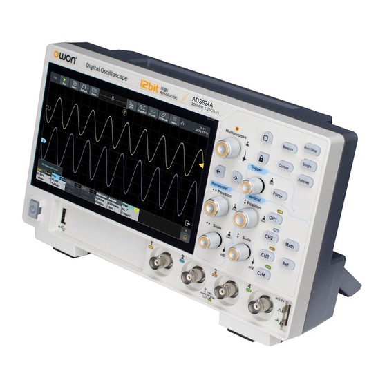
- Page 1 ADS800A Series User Manual ADS802A/804A ADS812A/814A ADS822A/824A For product support, visit:www.owon.com.hk/download ※:The illustrations, interface, icons and characters in the user manual may be slightly different from the actual product. Please refer to the actual product.
- Page 2 LILLIPUT Company. Fujian LILLIPUT Optoelectronics Technology Co., Ltd. No. 19, Heming Road Lantian Industrial Zone, Zhangzhou 363005 P.R. China Tel: +86-596-2130430 Fax: +86-596-2109272 Web: www.owon.com.cn E-mail: info@owon.com.cn...
-
Page 3: Table Of Contents
Table of Contents 1. General Safety Requirements ............1 2. Safety Terms And Symbols ..............3 How To Conduct A General Inspection .................5 How To Conduct Function Inspection ................... 6 3. Primary User Guide ................7 A General Knowledge Of The Structure Of The Instrument ..........8 Front Panel ........................8 Rear Panel ........................ - Page 4 How to Realize Waveform Operation Function ..........81 How To Set FFT ..................... 84 How To Set DIR(Digital Filtering) ................ 88 How To Set FRA (frequency response analysis) ..........89 How To Set Pass Fail .................... 91 How To Set Counter ....................94 How To Set DVM ....................96 How To Set Decode ....................99 How To Set Others Modulation ..................109...
- Page 5 Environment ........................147 Mechanical Specifications ..................147 7. Appendix ..................149 Appendix A: Accessories ....................149 Appendix B: General Care And Cleaning ................ 149...
-
Page 6: General Safety Requirements
1.General Safety Requirements General Safety Requirements Before use, please read the following safety precautions to avoid any possible bodily injury and to prevent this product or any other connected products from damage. In order to avoid any contingent danger, ensure this product is only used within the range specified. - Page 7 1.General Safety Requirements instrument. Avoid exposed circuit. Do not touch exposed junctions and components when the instrument is powered. Do not operate if in any doubt. If you suspect damage occurs to the instrument, have it inspected by qualified service personnel before further operations.
-
Page 8: Safety Terms And Symbols
2.Safety Terms And Symbols Safety Terms And Symbols Safety Terms Terms in this manual. The following terms may appear in this manual: Warning: Warning indicates the conditions or practices that could result in injury or loss of life. Caution: Caution indicates the conditions or practices that could result in damage to this product or other property. - Page 9 2.Safety Terms And Symbols To avoid body damage and prevent product and connected equipment damage, carefully read the following safety information before using the test tool. This product can only be used in the specified applications. Warning The four channels of the oscilloscope are not electrically isolated. The channels should adopt a common ground during measuring.
-
Page 10: How To Conduct A General Inspection
2.Safety Terms And Symbols Warning: To avoid fire or electrical shock, when the oscilloscope input signal connected is more than 42V peak (30Vrms) or on circuits of more than 4800VA, please take note of below items: Only use accessory insulated voltage probes and test lead. ... -
Page 11: How To Conduct Function Inspection
2.Safety Terms And Symbols 3. Check the Complete Instrument. If it is found that there is damage to the appearance of the instrument, or the instrument can not work normally, or fails in the performance test, please get in touch with our distributor responsible for this business or our local offices. -
Page 12: Primary User Guide
3.Primary User Guide Primary User Guide The following are illustrated with four channels as an example, and for two channels, please refer to four channels. Model Channel ADS802A ADS804A ADS812A ADS814A ADS822A ADS824A This chapter elaborates the following topics: A general knowledge of the structure of the instrument ... -
Page 13: A General Knowledge Of The Structure Of The Instrument
3.Primary User Guide A General Knowledge Of The Structure Of The Instrument This chapter gives a brief description and introduction to the operations and functions of the front panel of the instrument, so as to facilitate your operations of the instrument in the shortest time. Front Panel On the instrument panel, knobs and function buttons are used to enter different function menus or directly use specific function application. - Page 14 3.Primary User Guide turned to set the value. Example can rotate the knob to change the offset value. Arrow keys : Move to select the parameter. Home key : Return to the main homepage. Touch key : Press it to disable the touch screen, the key light turns on;...
-
Page 15: Rear Panel
3.Primary User Guide “Horizontal Scale” knob is to control time base scale. 6. Probe compensation: about 3.3V/1kHz signal output. 7. Channel input port area. 8. USB Host Interface: When the oscilloscope is connected to an external USB device as a “master device”, the USB Host interface is used to transmit the data (Note: the devices that can be connected include a mouse, keyboard, USB flash drive, etc.). -
Page 16: A General Knowledge Of The User Interface Of The Instrument
3.Primary User Guide 3. LAN Interface: The network interface to connect a PC or router. 4. USB Device Interface: When the oscilloscope is connected to an external USB device as a “slave device”, the USB Device interface is used to transmit the data. - Page 17 3.Primary User Guide 2. USB Device access identifier. 3. LAN port access identifier (If icon for the , it indicates the Wi-Fi is enabled and connected currently). Click the icon will switch to the Wireless&networks setting interface. 4. U disk access identifier. 5.
-
Page 18: Oscilloscope Inspection
3.Primary User Guide Oscilloscope Inspection 1. Set the Switch in the Oscilloscope Probe as 10X and Connect the Oscilloscope with CH1 Channel. Align the slot in the probe with the plug in the CH1 connector BNC, and then tighten the probe with rotating it to the right side. Connect the probe tip and the ground clamp to the connector of the probe compensator. -
Page 19: How To Set The Probe Attenuation Coefficient
3.Primary User Guide probe hook tip is used, ensure that it keeps in close touch with the probe. Connect the probe tip with the signal connector of the probe compensator and connect the reference wire clamp with the ground wire connector of the probe connector, and then push the Autoset button on the front panel. -
Page 20: How To Use The Probe Safely
3.Primary User Guide Caution: The default attenuation coefficient of the probe on the instrument is preset to 10X. Make sure that the set value of the attenuation switch in the probe is the same as the menu selection of the probe attenuation coefficient in the oscilloscope. -
Page 21: How To Conduct Self-Calibration
3.Primary User Guide the instrument and connect the ground terminal to the earth. How To Conduct Self-Calibration Self-calibration program is used to quickly make the oscilloscope be in the optimum condition to obtain the most accurate measurement. This program can be performed at any time. It is especially necessary when the ambient temperature reaches or exceeds 5℃. -
Page 22: Use The Android System
4.Use the Android System Use the Android System Android System Homepage Window 1. Application shortcut key. If you click the oscilloscope shortcut key, you can enter the oscilloscope interface. 2. App Drawer (Click to see all apps). 3. Task key. 4. - Page 23 4.Use the Android System...
-
Page 24: Use The Oscilloscope
5.Use the Oscilloscope Use the Oscilloscope A General Knowledge Of Oscilloscope A General Knowledge Of Trigger System As shown in Figure , there are one knob and one key. The following exercises are to guide you through the use of the trigger system. Figure 5-1: Trigger control area 1. -
Page 25: A General Knowledge Of Vertical System
5.Use the Oscilloscope Figure 5-2:Horizontal control area 1. Rotary Horizontal Position knob to adjust the horizontal position of the signal in the waveform window. The Horizontal Position knob is to control the triggered horizontal position of the signal; when turning the knob, the waveform moves horizontally with the knob. - Page 26 5.Use the Oscilloscope Figure 5-3: Vertical control area 1. Vertical Position knob to control the vertical display position of the signal. When turning the Vertical Position knob, the pointer indicating the Grounding Reference Point of the channel moves up and down following the waveform.
-
Page 27: How To Use Touch Screen Control
5.Use the Oscilloscope information display bar changes accordingly. 3. Press CH1、CH2、CH3、CH4 key to enable or disable the corresponding channel. If the current channel is disable, press it to enable and select the channel; If the current channel is enable but no selected, press it to select the channel;... - Page 28 5.Use the Oscilloscope Scroll List: When the scroll bar appears in the menu, swipe the screen up and down with the finger to scroll the list, as shown in the figure below. Open Main Menu: Click the icon in the lower right of the display area, the main menu window pops up, as shown below.
-
Page 29: Operate The Touch Screen
5.Use the Oscilloscope Operate The Touch Screen Select a Channel (CH1 channel, CH2 channel, CH3 channel or CH4 channel): Click the channel pointer on the left or click the channel waveform to make the channel pointer selected. Long press the channel pointer, the vertical position of waveform can be center. - Page 30 5.Use the Oscilloscope Set Horizontal Position (Horizontal Position knob): The horizontal position of the waveform can be changed by swiping your finger around the waveform display area, as shown in the figure below. The control voltage gear and time base can be scaled in the following way: ...
-
Page 31: Operate The Touch Screen In Waveform Amplification Mode
5.Use the Oscilloscope In the waveform display area, double-click the screen and slide the hand up and down/left and right to zoom the control voltage scale and time base. Operate The Touch Screen In Waveform Amplification Mode Press Horizontal Scale knob to enter the waveform zoom mode, the main window is displayed at the top half of the screen and the amplified window is displayed at the bottom half of the screen. -
Page 32: Other Touch Screen Operations
5.Use the Oscilloscope Other Touch Screen Operations Click and drag the open menu item to move itself to the appropriate location. Control the horizontal or vertical cursor lines under cursor measurement,... - Page 33 5.Use the Oscilloscope as shown in the figure below. Run/Stop: Click in the upper left of the display area to switch Run/Stop. Parameter Setting Keyboard in Menu Item: There are digital input mode and hobbing input mode. Digital input mode, as shown in the figure below. Hobbing input mode, as shown in the figure below.
- Page 34 5.Use the Oscilloscope Swipe the information display bar...
-
Page 35: Advanced User Guide For Oscilloscope
5.Use the Oscilloscope Advanced User Guide for Oscilloscope In the previous chapter, basic operations of the oscilloscope, function area of the front panel and the roles of the keys and knobs are introduced for the user to determine the change of instrument settings by observing the status bar. -
Page 36: How To Set Vertical System
5.Use the Oscilloscope How To Set Vertical System In the vertical system control area, there are six keys (CH1, CH2, CH3, CH4, Math and Ref) and two knobs (Vertical Position knob and Vertical Scale knob). Channel Settings Each channel is equipped with the independent vertical menu, and each item is set separately based on different channel. - Page 37 5.Use the Oscilloscope Pass the AC and DC component of the input signal. Coupling Block the DC component of the input signal. Ground Disconnect the input signal. Click to open or close the waveform Inverted inversion function. Click the Numeric Display Box and turn General knob or swipe the screen up and down in the numeric select box with the Common...
- Page 38 5.Use the Oscilloscope 500.0uV 100.0mV 1.000mV 200.0mV Select the optimum gear as required. 2.000mV 500.0mV Note: Scale 5.000mV 1.000V Current unit selection is V and the 10.00mV 2.000V voltage gear of the probe multiplier is 20.00mV 5.000V 50.00mV 10.00V According to requirement to set offset div, Current Unit unit.
- Page 39 5.Use the Oscilloscope enabled. Click Inverted switch gain to gray it, the waveform inversion will be disabled. 3. Adjust Probe Ratio It is required to adjust the coefficient of the probe attenuation ratio in the channel operation menu (see “How to Set the Probe Attenuation Coefficient”...
- Page 40 5.Use the Oscilloscope (3) Select the oscilloscope bandwidth in the Limit option. Click 20MHz. The bandwidth is limited to 20MHz and the high-frequency components larger than 20MHz contained in the measured signal will be blocked. Click All. The high-frequency components contained in the measured signal can be passed through.
-
Page 41: How To Set Horizontal System
5.Use the Oscilloscope general knob to set the required vertical position. Application of Math key and Ref key See "How to Realize Waveform Operation Function" on page 81 for the Math key. See "How To Set Reference Waveform" on page 125 for the Ref key. Application of Vertical Position knob and Vertical Scale knob 1.Vertical Position knob to adjust the vertical position of corresponding channel waveform. -
Page 42: Settings Descriptions
5.Use the Oscilloscope time base. 2. Horizontal Scale knob: Set the horizontal scale factor for the main window or amplified window. The descriptions of horizontal system menu are shown in the table below: Menu Settings Descriptions Zoom Mode Click to open/close zoom mode. Through the navigation function, observe the situation of moving waveform. - Page 43 5.Use the Oscilloscope In normal mode, the Horizontal Position knob and the Horizontal Scale knob are used to adjust the horizontal position and the horizontal time base of the main window. In waveform amplification mode, the Horizontal Position knob and the Horizontal Scale knob are used to adjust the horizontal position and the horizontal time base of the amplified window.
-
Page 44: How To Set Acquire
5.Use the Oscilloscope (Play left) or (Play right) can change the play direction, and it stops playing when it reaches the leftmost or rightmost end. In the stop mode: Click , the waveform can play directly to the far left;click the waveform can play directly to the far right. - Page 45 5.Use the Oscilloscope Used to reduce random and irrelevant noise in Average signal. Click the number input box and scroll down the list to the right to select the average count. Click to enable/disable the segment acquisition function. When the function is turned on, click Numeric Input Box to input the number of segment Segmentati acquisition and click OK to confirm;...
-
Page 46: How To Set Trigger
5.Use the Oscilloscope How To Set Trigger Trigger determines when the oscilloscope starts to collect the data and display the waveform. Once it is set properly, it can convert unstable display into the meaningful waveform. When the oscilloscope starts to collect the data, enough data are used to draw the waveform at the left of the trigger point. - Page 47 5.Use the Oscilloscope Trigger” is selected, it is triggered on the rising edge and falling edge of the input signal. Enter the edge trigger and the trigger setting information is displayed at the lower part of the screen, such as , indicating that the edge trigger is selected with the trigger signal source of CH1, trigger coupling of DC, slope of rising edge, and trigger level of 0.000pV.
-
Page 48: Video Trigger
5.Use the Oscilloscope restarting the trigger circuit, and click < > or press to move the cursor and select the digit to be set. 100ns Set the trigger hold-off time as 100ns. Set the sensitivity of the trigger window. Sensitivity Auto Set to collect waveform even when no trigger condition is detected. -
Page 49: Pulse Trigger
5.Use the Oscilloscope confirm; or click Gear Input Box (- or +) or turn the General knob to set the number of specified line, and click < > or press to move the cursor and select the digit to be set. 100ns –... -
Page 50: Slope Trigger
5.Use the Oscilloscope Click to set the pulse condition, click time setting’s Numeric Input Box to input the pulse > width time to be set and click the unit to confirm; = Time or click Gear Input Box (- or +) or turn the <... -
Page 51: Runt Trigger
5.Use the Oscilloscope Set the trigger type of the vertical channel to Type Slope slope trigger. Set Channel 1 as the signal source trigger signal. Set Channel 2 as the signal source trigger signal. Source Set Channel 3 as the signal source trigger signal. Set Channel 4 as the signal source trigger signal. - Page 52 5.Use the Oscilloscope Used to trigger a pulse that steps over one trigger level but not another. Enter the runt trigger and the trigger setting information is displayed at the lower part of the screen, such as , indicating that the runt trigger is selected with the trigger signal source of CH1, the polarity of positive runt and 0.000pV of the difference between upper level and lower level, as shown in the figure.
-
Page 53: Windows Trigger
5.Use the Oscilloscope Click to set the pulse width conditions, click Time setting time setting’s Numeric Input Box to input the pulse width to be set and click the unit to confirm; or click Gear Input Box (- or +) or turn General knob to set the pulse width, and click <... - Page 54 5.Use the Oscilloscope bottom right of the screen, for example, ,indicates that trigger type is windows, trigger source is CH1, polarity is positive, 0.000pV the differential between up level and low level threshold. The descriptions of windows trigger setting window are shown in the table below: Menu Settings...
-
Page 55: Timeout Trigger
5.Use the Oscilloscope 100ns – 10s; click Numeric Input Box to input the interval to be set for restarting the trigger circuit and click the unit to confirm; or click Gear Input Box (- or +) or turn the General knob to set HoldOff the interval for restarting the trigger circuit, and click <... -
Page 56: Nth Edge Trigger
5.Use the Oscilloscope Set the idle time. It refers to the minimum time that the clock signal must be in idle state before Idle Time the oscilloscope begins to search for data that meets the trigger conditions. The idle time ranges from 30ns to 10s with default value of 100ns. - Page 57 5.Use the Oscilloscope The descriptions of the Nth edge trigger setting window are shown in the table below: Menu Settings Descriptions Set vertical channel trigger type as Nth Edge Type Nth Edge trigger. Set Channel 1 as the signal source trigger signal. Set Channel 2 as the signal source trigger signal.
-
Page 58: Logic Trigger
5.Use the Oscilloscope Click Numeric Display Box and turn General knob to set the required threshold. Threshold Click 50% and set the shortcut key of trigger level in the vertical midpoint of the trigger signal amplitude. 100ns – 10s; click Numeric Input Box to input the interval to be set for restarting the trigger circuit and click the unit to confirm;... - Page 59 5.Use the Oscilloscope Set CH1 as High Level, Low level, high or low level, Rise and Fall. CH1 Input Mode Set CH2 as High Level, Low level, high or low level, Rise and Fall. CH2 Input Mode Set CH3 as High Level, Low level, high or low level, Rise and Fall.
- Page 60 5.Use the Oscilloscope Click Numeric Display Box and turn General knob to set the CH3 Threshold. Click 50% and set the shortcut key of trigger level Threshold in the vertical midpoint of the trigger signal amplitude. Click Numeric Display Box and turn General knob to set the CH4 Threshold.
- Page 61 5.Use the Oscilloscope The descriptions of RS232 trigger setting window are shown in the table below: Menu Settings Descriptions RS232/ Type Set the buss trigger type to RS232/UART trigger. UART Set Channel 1 as the signal source trigger signal. Set Channel 2 as the signal source trigger signal. Source Set Channel 3 as the signal source trigger signal.
- Page 62 5.Use the Oscilloscope Trigger when an error frame is detected, and set after selecting this trigger condition: Stop Bit: Select “1 bit” or “2 bits”. Error Parity Check: “N/A” refers to no check; “Even” refers to even check and “Odd” refers to odd check;...
- Page 63 5.Use the Oscilloscope trigger type is selected with CH1 SCL trigger level of 400.0mV and CH2 SDA trigger level of 464.0mV. The descriptions of the I2C trigger setting window are as follows: Menu Settings Descriptions Type Set the bus trigger type to I2C. Set Channel 1 as SCL.
-
Page 64: Spi Trigger
5.Use the Oscilloscope Addr Bits Set the address bit width to “7-bit”, “8-bit” or “10-bit”. Addr The address ranges from 0 to 127, from 0 to 255 and from 0 to 1023 depending on the address bit width. Direction Set the data direction to read or write. Note: This setting is not available when the address bit width is 8. - Page 65 5.Use the Oscilloscope Enter the SPI bus trigger and the trigger setting information is displayed at the lower part of the screen, such as ,indicating that the SPI trigger mode is selected with the CH1 SCL trigger level of 400.0V and CH2 SDA trigger level of 466.0mV.
-
Page 66: Can Trigger
5.Use the Oscilloscope acquire the SDA at the falling edge of the clock. Set the number of bits in the serial data string Data Bits ranging from 4 to 32 bits; click Numeric Display Box and turn General Knob to set the data bit width. Data Set the data bit. - Page 67 5.Use the Oscilloscope Set Channel 1 as the signal source trigger signal. Set Channel 2 as the signal source trigger signal. Source Set Channel 3 as the signal source trigger signal. Set Channel 4 as the signal source trigger signal. CAN_H Actual CAN_H bus signal.
-
Page 68: Lin Trigger
5.Use the Oscilloscope Use the General knob and arrow keys on the panel to set Value the ID value required. Click Numeric Display Box and Byte select the byte length required Length for the set data, ranging from 1 Data to 8. - Page 69 5.Use the Oscilloscope Trigger with LIN bus based on signal Break,ID, ID/data and Data Error. The signal source and signal rate specified by LIN is required. Enter the LIN buss trigger and the trigger setting information is displayed at the lower right of the screen, such as ,indicating that the LIN trigger type is selected with the trigger signal source of CH1, baud rate of 1,200bps and trigger level of 1.800V.
-
Page 70: How To Set Analysis Modulation
5.Use the Oscilloscope Data Set the trigger condition to bit data error. Error 100ns – 10s; click Numeric Input Box to input the interval to be set for restarting the trigger circuit and click the unit to confirm; or click Gear Input Box (- or +) or turn the General knob to set the interval for HoldOff restarting the trigger circuit, and click <... - Page 71 5.Use the Oscilloscope Delay(1 -2 ), Delay(1 -2 ), Phase(1 -2 ), Phase(1 -2 ), Phase(1 -2 ), Phase(1 -2 ), FRR(1 -2 ), FRF(1 -2 ), FFR(1 -2 ), FFF(1 -2 ), LRR(1 -2 ), LRF(1 -2 ), LFR(1 -2 ) and LFF(1 -2 ). The descriptions of automatic measurement setting window is shown as follows: Figure 5-5:Automatic measurement...
- Page 72 5.Use the Oscilloscope Click to close measuring menu. Click to delete all added measuring types. Click to display all measuring values of current opened channel. Add/Delete The waveform channel must be opened for measurement. Automatic measurement can not be performed when storing the waveform or calculating double waveforms.
- Page 73 5.Use the Oscilloscope Rise Time: Time that the leading edge of the first pulse in the waveform takes to rise from 10% to 90% of its amplitude. Fall Time: Time that the falling edge of the first pulse in the waveform takes to fall from 90% to 10% of its amplitude.
- Page 74 5.Use the Oscilloscope Vmax: The maximum amplitude. The most positive peak voltage measured over the entire waveform. Vmin: The minimum amplitude. The most negative peak voltage measured over the entire waveform. Vtop: Voltage of the waveform's flat top, useful for square/pulse waveforms. CycRms: The true Root Mean Square voltage over the first entire period of the waveform.
- Page 75 5.Use the Oscilloscope waveform within the screen. CycArea : The area of the first period of waveform on the screen and the unit is voltage-second. The area above the zero reference (namely the vertical offset) is positive and the area below the zero reference is negative. The area measured is the algebraic sum of the area of the whole period waveform.
- Page 76 5.Use the Oscilloscope Delay( - ): The time difference between the lower rising edge of source A and the upper falling edge of source B at the middle value of the threshold. Negative delay indicates that the lower rising edge of source A occurs after the upper falling edge of source B.
- Page 77 5.Use the Oscilloscope Phase( - ): The phase difference between the falling edge of source A and the rising edge of source B at the middle value of the threshold is expressed in degrees.Calculation formula is: Of which,PhaseA F B R is phase( - ),DelayA F B R is delay( - ),Period sourceA is source A period.
- Page 78 5.Use the Oscilloscope Click Avg & Std Sample Times Input Box, set the statistics number by pop up keyboard and also can rotate the corresponding multipurpose knob to set value. The value range of measurement times is 2 to 1000, default is ...
- Page 79 5.Use the Oscilloscope Horizontal Range: Selecting Screen indicates that the measurement range is the whole screen; selecting Cursor indicates that the measurement range is only within the cursor range. Top/Base: Set the measurement method for the top and bottom values of the amplitude.
-
Page 80: How To Set Xy Mode
5.Use the Oscilloscope How To Set XY Mode After XY mode is selected, both Channel 1 and Channel 2 are opened and one waveform amplitude is displayed relative to another. CH1 is displayed on the horizontal axis and CH2 is displayed on the vertical axis. Horizontal axis can select CH1, CH2, CH3 or CH4. - Page 81 5.Use the Oscilloscope Cursor Measurement in General Mode: The descriptions of cursor measurement setting window are shown in the table below: Menu Settings Descriptions Switch Open or close the cursor measurement. Select Cursor Mode. When Auto Mode is selected, the position of Manual Mode the horizontal cursor is automatically set to...
- Page 82 5.Use the Oscilloscope Select X1 vertical cursor line. Select X2 vertical cursor line. X1&X2 Select X1 and X2 vertical cursor lines simultaneously. Select a cursor line and turn General knob or drag the cursor line with the finger to move the cursor line. Select Y1 horizontal cursor line.
- Page 83 5.Use the Oscilloscope 5. Set Cursor Line Click Y1 or Y2 in the Cursor Line menu, turn General knob to move the cursor lines Y1 or Y2 up and down; select Y1&Y2 and turn General knob to move the cursor lines Y1 and Y2 up and down simultaneously; ...
- Page 84 5.Use the Oscilloscope Click X in the type menu to highlight it, and two dotted lines X1 and X2 are displayed in the horizontal direction of the screen; Click Y in the type menu to highlight it, and two dotted lines Y1 and Y2 are displayed in the horizontal direction of the screen;...
- Page 85 5.Use the Oscilloscope Y2 are displayed in the horizontal direction of the screen; Click XY in the type menu and two pink dotted lines X1 and X2 in the vertical direction and two pink dotted lines Y1 and Y2 in the horizontal direction are displayed on the screen.
-
Page 86: How To Realize Waveform Operation Function
5.Use the Oscilloscope How to Realize Waveform Operation Function Waveform operation functions include addition, subtraction, multiplication, division, integration, differentiation, square root and custom function operations for Channel 1, Channel 2 , Channel 3 and Channel 4 waveforms. Click in the right corner of the screen, then select Math to display setting window, as shown in the figure below. - Page 87 5.Use the Oscilloscope Click Numeric Input Box to directly input the vertical position of the Math waveform to be set and click the unit to confirm; or click Gear Input Box (- or +) or turn General knob to set the vertical Vertical position of Math waveform to be set, click <...
- Page 88 5.Use the Oscilloscope 1. Click in the right corner of screen, then select Math ,the screen will pop up math setting window. 2. Click Switch to highlight it, and the pink waveform M will display on the screen. 3. Click Advanced to highlight it. 4.
-
Page 89: How To Set Fft
5.Use the Oscilloscope of Math waveform to be set and click the unit to confirm; or click Gear Input Box (- or +) or turn General knob to set the vertical position of Math waveform to be set and click < > or press to move the cursor and select the digit to be set. - Page 90 5.Use the Oscilloscope FFT operating steps are as follows: 1. Click in the right corner of screen,then select FFT , the screen will pop up FFT setting window. 2. Click Switch when the switch label is highlighted on the right, it is enabled. The pink waveform M will be displayed on the screen (It is also available to click FFT shortcut softkey at the upper part of the screen).
- Page 91 5.Use the Oscilloscope The peak display list is displayed at the top left of the waveform. 9. Click Number Peaks Numeric Display Box , set the value required and setting range is 1 to 15. 10. Click Threshold Numeric Display Box and set the value required.The threshold range is related to the current FFT gear and offset.
- Page 92 5.Use the Oscilloscope Better solution for amplitude than Rectangle, and good for frequency as well. It has slightly better frequency resolution than Hanning. Recommend to use for: Hamming Sine, periodic and narrow band random noise. Transients or bursts where the signal levels ...
-
Page 93: How To Set Dir(Digital Filtering)
5.Use the Oscilloscope digitizing oscilloscope can acquire without aliasing. This frequency is half of the sample rate. Frequencies above the Nyquist frequency will be under sampled, which causes aliasing. So pay more attention to the relation between the frequency being sampled and measured. How To Set DIR(Digital Filtering) Digital filtering supports low pass, high pass, band pass and band reject types, and the specific frequency in the signal can be filtered out by setting the cut-off... -
Page 94: How To Set Fra (Frequency Response Analysis)
5.Use the Oscilloscope the lower part of the menu. 7. Click Vertical in the option, directly click Numeric Input Box to input the vertical position of the Math Waveform to be set and click the unit or OK to confirm; or click Gear Input Box (- or +) or turn General knob to set the vertical position of the Math Waveform to be set, click <... - Page 95 5.Use the Oscilloscope Set the stop value of sweep frequency, ranging from 10Hz to 25MHZ with the default value of 25MHz. End Freq Note: The value of “End Frequency” shall be set larger than that of “Start Frequency”. Set the voltage amplitudes for different frequency ranges. Amplitude Note: The amplitude ranges from 2mV to 6V.
-
Page 96: How To Set Pass Fail
5.Use the Oscilloscope Under FRA Analysis End of FRA Analysis How To Set Pass Fail Click Pass Fail in the analysis module from the main menu window at the lower right of the screen. The descriptions of the setting window are shown in... - Page 97 5.Use the Oscilloscope the table below: Menu Settings Descriptions Switch Open or close Pass/Fail measure function. Operate Control operate switch. Select CH1,CH2,CH3 or CH4 Source source. Select pass or fail set type. PASS Pass: measured signal Category conforms to the set rules. FAIL Fail: The measured signal doesn’t Configuration...
- Page 98 5.Use the Oscilloscope the right, it is enabled. 3. Configuration: In the configuration menu,set output type is PASS or FAIL; set output mode whether to open Stop or Beep; set whether to open Message Display. 4. TheMaskRule: In TheMaskRule menu select Source, in Horizontally Disposed or Vertically Disposed , click Numeric Input Box , set horizontal value or vertical value;...
-
Page 99: How To Set Counter
5.Use the Oscilloscope How To Set Counter To perform counter, follow these steps: 1. Click Counter in the analysis module in the main setting window at the bottom right of the screen The setting window will display on the screen. 2. - Page 100 5.Use the Oscilloscope 6. Click Reset Stat., the historical data of the counter will be cleared and the statistics will be re-conducted.
-
Page 101: How To Set Dvm
5.Use the Oscilloscope How To Set DVM To perform DVM, follow these steps: 1. Click DVM in the analysis module in the main setting window at the bottom right of the screen The setting window will display on the screen. 2. - Page 102 5.Use the Oscilloscope can directly enable or disable the statistics function. 6. Click Reset Stat., the historical data of the DVM will be cleared and the statistics will be re-conducted. 7. Click Magnifier Box when the switch label is highlighted on the right, it is enabled.
- Page 103 5.Use the Oscilloscope 8. Alarm: In the Upper Limit or Lower Limit option, click Numeric Input Box to set the upper or lower limit vale. In When Limit to set the limit condition to In Limit or Out Limit. Set the switch whether to turn on the alarm sound.
-
Page 104: How To Set Decode
5.Use the Oscilloscope How To Set Decode To perform Decode, follow these steps: 1. Click Decode in the analysis module in the main setting window at the bottom right of the screen 2. The setting window will display on the screen. Click Decode1 or Decode2 to set decode. - Page 105 5.Use the Oscilloscope In the Path option, select the storage path as Internal or External; click Name Input Box can edit the filename or save the waveform with the system default filename, the file format is csv; click Export , can save the file.
-
Page 106: Menu Settings
5.Use the Oscilloscope When decoding, if "Parity" is not set to "None", and the check bit error is detected, P marks will be displayed in the corresponding position in the waveform. The descriptions of RS232/UART decode setting window are as shown in the table below: Menu Settings... - Page 107 5.Use the Oscilloscope LSB:Least Significant Bit, that is, the data is transmitted low first. Endian MSB:Most Significant Bit, that is, the data is transmitted high first. DECIMAL Format Select the display format to decode. BINARY ASCII Switch, Click when switch label Event highlighted on the right, it is enabled.The decode...
- Page 108 5.Use the Oscilloscope Menu Settings Descriptions Click Switch, when the switch label is highlighted on the right, it is enabled. Switch Copy Trig Click the Copy Trig button to copy the current trigger settings to the decoding function. Type Set the decode type as I2C. Select CH1,CH2,CH3 or CH4 as SCL.
- Page 109 5.Use the Oscilloscope (1) Connect the clock line (SCLK) and the data line (SDA) of the SPI signal to the Signal Input Channels of the oscilloscope. (2) Adjust to the proper time base and voltage division. (3) In trigger menu, select trigger type as SPI, set parameters based on the characteristics of the signal, trigger the signal correctly and obtain stable display.
- Page 110 5.Use the Oscilloscope Click Numeric Display Box and turn General knob to set the lower threshold; Click 50% and set the shortcut key of trigger level in the vertical midpoint of the trigger signal amplitude. MISO Select CH1,CH2,CH3 or CH4 as MISO. Click Numeric Display Box and turn General knob to set the lower threshold;...
- Page 111 5.Use the Oscilloscope DECIMAL Format Select the display format to decode. BINARY ASCII Click Switch, when switch label Event highlighted on the right, it is enabled.The decode Table list will display on the screen. Click Label, when the switch label is highlighted Common on the right, it is enabled.You can select Label...
- Page 112 5.Use the Oscilloscope Type Set the decode type as CAN. Select CH1,CH2,CH3 or CH4 as the decode Source signal source. Click Numeric Display Box and turn General knob to set the lower threshold; Click 50% and set the shortcut key of trigger Threshold level in the vertical midpoint of the trigger signal amplitude.
- Page 113 5.Use the Oscilloscope characteristics of the signal, trigger the signal correctly and obtain stable display. Refer to “LIN Trigger” P68. (4) After the signal is stabilized and triggered, click Decode in the analysis module in the main setting window at the bottom right of the screen Select the type as LIN, set parameters based on the characteristics of the signal.
-
Page 114: How To Set Others Modulation
5.Use the Oscilloscope DECIMAL Format Select the display format to decode. BINARY ASCII Click Switch, when switch label Event highlighted on the right, it is enabled.The decode Table list will display on the screen. Click Label, when the switch label is highlighted Common on the right, it is enabled.You can select Label... - Page 115 5.Use the Oscilloscope rate . Select the current screen grid type. FULL: Indicates that the number of display grids on the screen is full. Open background grid,indicates that the number of display grids on the screen is full. Open background grid.
-
Page 116: How To Save And Print
5.Use the Oscilloscope display. (4) Select Clear in the menu to erase previously collected results from the display, and the oscilloscope will start cumulative collection again. Color Grade: The color temperature display function uses the color level to indicate the frequency of waveform occurrence. - Page 117 5.Use the Oscilloscope Format Select the waveform save format. Matlab Select the waveform to be saved, it is available to save CH1 and/or CH2 and/or CH3 and/or Source CH4 waveforms(When a channel is not open, it can not be saved). Save the wave by editing the file name or the Name system default file name.
- Page 118 5.Use the Oscilloscope Open or close the save background for the printed image. When inverting color is Inverse opening , the image will be printed with a white background. Open or close the time for printing images. When enabled, the printed image will display Time the specific printing time of the image in the lower right corner of the image.
- Page 119 5.Use the Oscilloscope Figure 1 ②Click Open to installation package, as shown in Figure 2. Figure 2 ③Click INSTALL,start to install print app, as shown in Figure 3.
- Page 120 5.Use the Oscilloscope Figure 3 ④ Software install produce,as shown in Figure 4. Figure 4 ⑤After install success, click OPEN can open print app. As shown in Figure 5.
- Page 121 5.Use the Oscilloscope Figure 5 3、Open the installed printing software, as shown in Figure 6. Go to the last page and check "Agree" license agreement and privacy policy. Click "I AGREE" to start using the software, as shown in Figure 7. Figure 6...
- Page 122 5.Use the Oscilloscope Figure 7 4 、 After entering the printing software interface, click "Enable Wi-Fi to see nearby printers" to connect the printer's Wi-Fi, as shown in Figure 8. The Wi-Fi connection is successful, as shown in Figure 9. Figure 8...
- Page 123 5.Use the Oscilloscope Figure 9 5、In the menu below, set the printing parameters. Click to open Inverse , the image will be printed with a white background. Click to open Time, the image will display specific printing time of the image. Select printing area: Full Screen or Waveform Area.
- Page 124 5.Use the Oscilloscope 7、Click can set the parameter including: Copies, Paper Size, Color, Orientation, Two-sided and Pages. After setting, click the print icon to print the image, as shown below. Note: Image printing can only be printed over a network connection, USB connection is not valid.
- Page 125 5.Use the Oscilloscope not be found, do not connect at the same time. USB Flash Drive Requirements System-supported USB flash drive format: The file system type is FAT32 and the size of the allocation unit can not exceed 4K. Large-capacity USB flash drive is supported.
- Page 126 5.Use the Oscilloscope Figure 5- 9: Disk Management of computer 4. Right click 1 or 2 red mark area, choose Format. And system will pop up a warning message, click Yes. Figure 5- 10: Format the USB disk warning 5. Set File System as FAT32, Allocation unit size Default. Check "Perform a quick format"...
- Page 127 5.Use the Oscilloscope Figure 5- 11: Formatting the USB disk setting 6. Formatting process. Figure 5- 12:Formatting the USB disk Check whether the USB disk is FAT32 with allocation unit size 4096 after formatting. Use Minitool Partition Wizard to format Download URL: http://www.partitionwizard.com/free-partition-manager.html Tip: There are many tools for the USB disk formatting on the market, just take...
- Page 128 5.Use the Oscilloscope 1. Connect the USB disk to the computer. 2. Open the software Minitool Partition Wizard. 3. Enter the app interface and information about the USB disk will display on the right side with red mark 1 and 2. Figure 5- 13:Reload Disk 4.
- Page 129 5.Use the Oscilloscope Figure 5- 15:Format setting 6. Click Apply at the top left of the menu. Then click Yes on the pop-up warning to begin formatting. Figure 5- 16:Apply setting 7. Formatting process.
-
Page 130: How To Set Reference Waveform
5.Use the Oscilloscope Figure 5- 17:Format process 8. Format the USB disk successfully. Figure 5- 18: Format successfully How To Set Reference Waveform 100 reference waveforms can be stored in the instrument, which can be displayed with current waveform simultaneously. The stored waveform can not be adjusted after being called. - Page 131 5.Use the Oscilloscope To store CH1 channel waveform to waveform0, operate according to the following steps: 1. Open CH1 channel. 2. Click Reference in the others module in the main setting window at the bottom right of the screen 3. The setting window will display on the screen.Click Switch when the switch label is highlighted on the right, it is enabled.
-
Page 132: How To Conduct Self-Calibration
5.Use the Oscilloscope When the display switch is closed, the label disappears and the reference waveform displayed on the screen will be hidden accordingly. 8. Click Label to select a common type or a Custom type. When you select a common type, you can select 31 types of labels. When you select a Custom type, you can click the input box below to enter the required labels. -
Page 133: How To Set Network
5.Use the Oscilloscope screen.Click Start to perform the probe check. After completing the probe check, the check results are displayed on the screen and click Quit. If the result is undercompensation or overcompensation, please refer to “How to Implement the Probe Compensation”... - Page 134 5.Use the Oscilloscope How To Set Up a Network Discovery Service 1. Click Network in the others module in the main setting window at the bottom right of the screen 2. Click mDNS when the switch label is highlighted on the right,it is enable. LXI software can be used for network discovery services;...
- Page 135 5.Use the Oscilloscope LXI Discovery Tool software is taken as an example to explain, and the detailed operation is as follows: (1) Open LXI app, enter the app interface,as shown in the following picture. (2) Click on the Settings in the top left corner and select "Advance View" as shown below.
- Page 136 5.Use the Oscilloscope (4) Under the“Advance Settings View”interface, select mDNS,mDNS Service Type select“_http._tcp”, as shown below. (5) After setting, click Search, available devices can be searched, and the IP address of the device and the corresponding instrument description are displayed,as shown below.
-
Page 137: Default
5.Use the Oscilloscope (6) Select your own instrument, click the corresponding instrument description or click "Open Web Page" in the lower right corner to jump to the network service login interface, as shown below. Default Restore the factory settings. Click Default shortcut in the left corner of screen and click Confirm in the factory settings window, to restore the factory default state;... -
Page 138: About
5.Use the Oscilloscope About It is composed of About the Application and About the Instrument. The former is to display the latest version of the instrument; and the latter is to show the instrument Product Model, Serial Number, System Version and CheckSum. - Page 139 5.Use the Oscilloscope measurement results with other devices or systems for more accurate and comprehensive measurement, analysis, and control. The output types of the synchronous output of this instrument are trigger output and pass/fail, which can help the user better control and analyze the trigger and validity of the measurement process.
-
Page 140: Hardware-Test
5.Use the Oscilloscope Window time: Set window display time, the value can be set Close, 5s, 10s, 15s, 20s, 25s, 30s. When the set time is up, the setting window will automatically close. Beeper: Click Beeper when the switch label is highlighted on the right, it is enabled. - Page 141 5.Use the Oscilloscope Signal open or close (channel switch Channel switch remains closed) Vertical Scale Adjust to the proper scale Channel Bandwidth Current Horizontal Position Center or two squares to left or right Horizontal Scale Adjust to the proper scale Trigger Type Rising Trigger Signal Source CH1, CH2, CH3 or CH4...
- Page 142 5.Use the Oscilloscope DC level: cancel autoset, auxiliary menu set. Unknown source: cancel autoset , auxiliary menu set. Partial description of nouns: Signal period:Display 1~2 waveform periods. Multi periods:Display multiple waveform periods. Rising edge:Separate shows a rising edge of square wave. Falling edge:Separate shows a falling edge of square wave.
- Page 143 5.Use the Oscilloscope respectively. If the condition is not met, the automatic waveform setting may be invalid. Run/Stop: Run and Stop the waveform acquisition. Note: In the stop state, the vertical gear and horizontal time base of the waveform can be adjusted within a certain range, equivalent to extend the signal in the horizontal or vertical direction.
-
Page 144: Technical Specifications
6.Technical Specifications Technical Specifications Unless otherwise stated, all technical specifications apply to digital oscilloscope with the attenuation switch of the probe set to 10X. The instrument must be operated continuously for more than thirty minutes under the specified operating temperature. ... -
Page 145: Horizontal System
6.Technical Specifications Single bandwidth Full bandwidth Frequency coupling, ≥10 Hz (at BNC ) -3dB) ADS802A/ADS804A ≤ 5 ns Rising Time(at ADS812A/ADS814A ≤ 3.5 ns BNC, typical) ADS822A/ADS824A ≤ 1.75 ns ≤1 mV DC Gain Accuracy 2 mV ≥5 mV 1.5% Delta Volts between any two averages of ≥16 accuracy waveforms acquired with the same scope setup and... -
Page 146: Acquire System
6.Technical Specifications Acquire System Characteristics Instruction Acquire mode Sample, Peak, High Res, Average, Segmentation Four Channel, Dual Channel 625 MSa/s Maximum real-time acquire Dual Channel 1.25 GSa/s rate Single Channel 1.25 GSa/s Waveform Real-time acquire: 50,000 wfms/s capture rate Segment acquire: 700,000 wfms/s 1k,10k,100k,1M,10M,25M,50M Record length Note: The record length is dynamic, changing with the... -
Page 147: Trigger Type
6.Technical Specifications Holdoff range 100 ns to 10s Trigger sensitivity 0.3 div ~ 10 div Trigger level range Internal ±4 divs from the center of the screen Trigger Type Characteristics Instruction Couple DC, AC, HF Edge Trigger Slope Rising, Falling Support standard NTSC, PAL and Modulation SECAM broadcast systems... -
Page 148: Waveform
6.Technical Specifications Data Bits 5 bits, 6 bits, 7 bits, 8 bits Start, Restart, Stop, Ack Lost, Addr, Trigger Condition Data, Addr/Data 7 bits---->0 to 127 I2C Trigger Address Range 8 bits---->0 to 255 /Byte Length 10 bits--->0 to 1023 ByteLength 1 to 5 Trigger Condition Timeout, CS... -
Page 149: Waveform Analysis
6.Technical Specifications 43 automatic measurements with up to 8 Number measurements displayed simultaneously Measurem CH1 - CH4 ent source Measurem Primary time base, extended time base, ent area cursor area Period, Width, Rise Time, +Duty, Vertical Frequency, - Width, Fall Time, -Duty and ScrDuty Vavg, Vpp, Vamp, StdDev, Vmax, Vtop, Auto... -
Page 150: Decode
6.Technical Specifications Waveform brightness brightness Acquire mode Only basic waveforms are supported Decode Characteristics Instruction 2, Both protocol types can be decoded and switched Decode Number simultaneously Decode Type RS232/UART, I2C, SPI, LIN, CAN Decode RS232/UART bus TX/RX signals at speeds up to 10 Mb/s (5 to 8 bits), supporting parity bit (odd parity, RS232/UART even parity, or no parity) and stop bit (1 to 2 bits) -
Page 151: Dvm
6.Technical Specifications Measurement Frequency, period type Statistic Type, Max, Min, Avg parameter Maximum Maximum analog bandwidth frequency Resolution 6 bits Characteristics Instruction Source CH1, CH2, CH3, CH4 Function AC RMS, DC, AC+DC RMS Resolution 4 bits Support upper and lower limit setting, over-limit Limit warnings condition setting, over-limit prompt Command... -
Page 152: Processor System
6.Technical Specifications Off, infinity, adjustable time (1 second, 2 seconds, 5 Afterglow seconds) Brightness level 256 levels Processor system Characteristic Instruction System memory 2GB RAM Operating Android system Internal non-volatile memory Output of the Probe Compensator Characteristics Instruction Output About 3.3 V, with the Peak-to-Peak voltage ≥1MΩ voltage(typical) Frequency(typical) 1 kHz Square Others... - Page 153 6.Technical Specifications Characteristics Instruction 260 mm(L)*160 mm(H)*78 mm(W) Dimension Weight Approx. 1.5kg Interval Period of Adjustment: One year is recommended for the calibration interval period.
-
Page 154: Appendix A: Accessories
7.Appendix Appendix Appendix A: Accessories (The accessories subject to final delivery.) Standard Accessories: Power Cord Quick Guide USB Cable Probe Power Supply Adaptor Optional Accessories: BNC to alligator clip cable Appendix B: General Care And Cleaning General Care Do not store or leave the instrument where the liquid crystal display will be exposed to direct sunlight for long periods of time. - Page 155 7.Appendix 2. Disconnect power before cleaning your Oscilloscope. Clean the instrument with a wet soft cloth not dripping water. It is recommended to scrub with soft detergent or fresh water. To avoid damage to the instrument or probe, do not use any corrosive chemical cleaning agent. Warning: Before power on again for operation, it is required to confirm that the instrument has already been dried completely, avoiding any electrical short circuit or bodily injury resulting...
Need help?
Do you have a question about the ADS800A Series and is the answer not in the manual?
Questions and answers