Table of Contents
Advertisement
Quick Links
F
"_L. Save This Manual
For Future Reference
Operators
Manual
MODEL NO.
113.197110
OR
113,197150
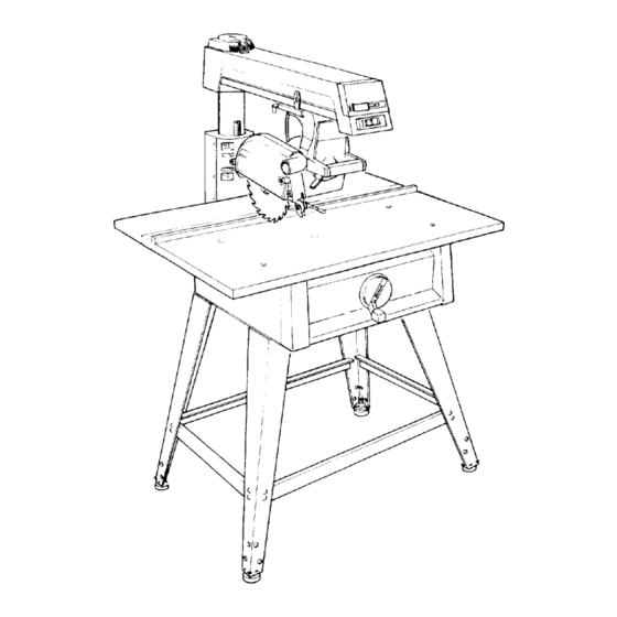
10" RADIAL SAW
WITH LEG SET
Serial
Number
Model and serial numbers
may be found at the rear of
the base.
You should record both
model and serial number in
a safe place for future use.
CAUTION:
READ ALL
INSTRUCTIONS
CAREFULLY
CRRFTSMRN
10-INCH RADIAL SAW
• Assembly
• Operating
• Repair parts
Sold by SEARS,
ROEBUCK
AND CO., Chicago,
IL. 60684 U.S.A.
Part No. SP5249
Printed in U.S.A.
Advertisement
Table of Contents

Related Manuals for Craftsman 113.197110


Summary of Contents for Craftsman 113.197110
- Page 1 "_L. Save This Manual For Future Reference Operators Manual MODEL NO. 113.197110 113,197150 10" RADIAL SAW WITH LEG SET Serial CRRFTSMRN Number Model and serial numbers may be found at the rear of the base. You should record both model and serial number in 10-INCH RADIAL SAW a safe place for future use.
- Page 2 FULL ONE YEAR WARRANTY ON CRAFTSMAN RADIAL SAW It within one year from the date of purchase, this Craftsman Radial Saw fails due to a defect in material or workmanship, Sears will repair it, free of charge. WARRANTY SERVICE AVAILABLE...
- Page 3 Safety Information The operator's manual contains safety infor- Major Hazards mation, instructions and signs for your protec- tion against serious injuries, including: 1. Workpiece Kickback Loss of fingers, hand, arm or leg from contact Kickback is an uncontrolled grabbing with the saw blade. throwing of the workpiece during ripping.
- Page 4 3. Wrong Way Feed Wrong way feed is feeding the workpiece into the end of the saw with the anti-kickback pawls. The workpiece can be grabbed by the can be blinded blade and puli your hands into the blade before you can let go or pull back.
- Page 5 Salty Personal Safety 1. Keep guards and anti-kickback pav_l_in 1. Wear safety goggles labeled "ANSI Z87.1" place and in working order. on the package. Do not wear regular glasses, they are not safety glasses. 2. Check for broken or damaged parts before 2.
- Page 6 14. Rip workpieces that are longer than Safety Labels on the Radial Arm Saw diameter of the blade being used. Do not rip The following labels are on your radial arm a workpiece that is shorter than the diameter saw. Locate, read and follow the safety in- of the blade being...
- Page 7 Putting Your Saw Together Your radial arm saw is easy to put together, however it will take time. Ask a friend to help, and follow these assembly instructions. It is important for your safety, and for the quality of your cuts, that the saw be put together with care.
- Page 8 ©° 4. Open the loose parts bags, and sort the contents into piles on the floor or table. This will make it easier for you to find the part(s) ©P you need during assembly. Truss Screw 1/4-20 x 1/2 ..Hex Nut 1/4-20 ....
- Page 9 Information 2. Place the hex bushing inside the_handwh_l. 1. If you are missing any part while putting 3. The hex bushing has a small flati_ea:pnli which matches a flat area on the elevatidn your saw together, do not continue assembly. shaft.
- Page 10 5. Clean the small pieces of styrofoam off If the bevel lock touches the left side of the the saw. yoke, unlock the bevel lock and tighten Iocknut on the motor pivot support. Then 6. Place the motor on the center channel to step 9 and repeat,...
- Page 11 Switch Front _tt_he_J'He_! Hex Nuts Support Bracket __keveling Foot Fig. 19 \ Floor Column Support Cover Building the LEG SET 4. Mount the two front legs to the basic saw The following parts are used in the leg set assembly using truss head bolts, lockwashers, assembly.
- Page 12 6. Attach the four (4) lower stiffeners to the 2. Loosen the bottom hex nut on the desired legs'. Two (2) truss head bolts, washers, leveling foot using a 9/16 inch wrench. nuts are required to hold each end of a lower stiffener in place.
- Page 13 • Location and Function of Controls ,111111 Fig. 24 - Radial Saw Controls WARNING: The saw can start ac- On/Off Switch cidentally or be used by children others when the yellow key is left in the The on/off switch turns the power to the saw red switch.
- Page 14 Bevel Lock The bevel lock is used to hold the blade at various angles to the table. To unlock bevel lock, move tile lock to the right. Always hold the motor when you unlock the bevel lock. (Figure _lb CAUTION: The motor is heavy and can swing down quickly.
- Page 15 swivH lock when the motor is inion'€ of ihese There are five pro-set bevel angles at -90 °, -45 °, 0 °. 45 °, and 90 °. To unlock the bevel positions, stand fiicing the saw l_smUtb, poill : the swivel lock :ill the way towar_yL, u, flTnLT lock when tile blade is at one of these angles, turn the motor as you hold the lock in this...
- Page 16 Handwheel The handwheel controls the height of the radial arm. To raise the radial arm, turn the handwheel clockwise. To lower the radial arm, turn the handwheel counterclockwise. (Figure Fig. 34 - Handwheel One complete turn of the handwheel moves the arm 1/16 inch.
- Page 17 Alignment of the Blade ALIGNMENT OF THE BLADE IS THE 1. Use a 3/16 hex "'L'" wrench to loosen MOST IMPORTANT STEP four screws in the front of the column support. ASSEMBLING YOUR RADIAL (Figure SAW. The blade of your radial arm saw must be aligned properly for two reasons:...
- Page 18 Leveling Table Supports 1. Raise the radial until the bottom Turn the motor until the arbor shaft the motor is about 2-1/2 inches above pointing straight down toward the saw. (Figure saw. Locate four hex head bolts and put a flat washer on each.
- Page 19 If the arbor wrench will not fit between arbor shaft and the table support _t any point repeat steps 8-21 until the table suppofls"are level, If there is a gap between the arbor wrench and the arbor shaft at any point, repeat steps 8-21 until the table supports...
- Page 20 Mounting the Front Table 1. Make sure that the front table is upside down. ;rew 2. Place a tee nut over the leveling hole Leveling Hole hammer it into place. (Figure Bolt Tee NL,t ---.-._,_ //_7_... Head Screw Leveling Hole ___i -_"...
- Page 21 If there is a gap larger than 1_3_. lge]_, 8. Install the pan head bolts through the other back to step 1 I and repeat, four mounting holes. Put a lockwasher hex nut on each bolt and tighten using If there is a gap less than 1/32 inch, or no gap Phillips screwdriver.
- Page 22 4. Unlock the rip lock and move the motor until the motor arbor is over the front table. 5. Lock the rip lock, miter lock bevel lock. 6. Lower the radial arm until the motor arbor is slightly above the front table. Four Socket Head Screws 7.
- Page 23 17. Lay a framing squareon the Mounting Table ClamPs front table with the long edge along the back of the table and the short edge alongside the motor arbor, The following parts are used in mounting as before. table clamps: Thumbscrews .....
- Page 24 6. Turn the blade with your hand several times 1. Place the radial in the 0 ° miter and check to see if the square is flush with position and lock the miter lock. blade. 2. Place the blade on the arborshaft with a 7.
- Page 25 11. Hold the motor tightly and lock the bevel If there is a gap between the square and the lock. Do not let the motor move out of place. blade after any rotation, go back to step8 repeat. 12. Check the square to make sure that it is still flush with the blade.
- Page 26 4. Turn the blade with your hand several times and check to see if the square is flush with the blade. 5. If the square is flush with the blade after each rotation, no change is needed. (Figure Go to the next section, If there is a gap between the square and the...
- Page 27 4. Turn the blade with your hand Se_t Squaring Blade to Table for times and check to see if the squ_tr_lflt Ripping with the blade. 1. Unlock the swivel lock and turn the motor to 5. If the square is flush with the blade after the out-rip position with the motor between...
- Page 28 15. ff you can keep either of the carriage 7. Hold the square in place and use the 9/16 bearings from turning while the motor moves inch wrench to turn the boltuntil the square along the radial arm, go to step 16, or is flush with the blade.
- Page 29 23. Turn the blade w'ith your hand several table under the blade and the short ed_e_i_ times and check to see if the square is flush sticking up in the air. Make sure that tl_!6fig with the blade. edge is perpendicular to the fence.
- Page 30 9. Unlock the bevel lock. 14. Tighten the two screws on the back of the motor support. 10. Loosen the two screws on the back of the motor support using a 3/16 inch hex-L wrench 15. Place the corner of the framing square and pliers if necessary.
- Page 31 _t_ WARNING" Kickback occur 3. Make sure that the lower edg_ _{_e _.@qd spreader is not in line with is parallel to the table. (Figure "_._L blade. be injured or killed. ways adjust spreader make sure 4. Tighten the guard clamp screw.
- Page 32 11. Lower the spreader and antikickbackpawls If the spreader is in front of the fence but not until the spreader is against the fence, and the touching it (Figure 81-B), go to step 13, or pawls on one side of the spreader are on top of the fence.
- Page 33 Installing and Adjusting Rip Scale Indica- 3. Measures 2" from rip lence,tdmear.e._ tors tooth on the blade and lock rip lock handle] NOTE: The rip scales indicators are intended Adjust "out rip" scale indicator by slid- to be used for quick settings. Adjustments ing until indicator line reads 2 inches on the...
- Page 34 Electrical Connections 4Ilk WARNING: To avoid shock or fire, if Motor Specifications power cord is worn, cut, or damaged any way have it replaced immediately. The AC motor used in this saw is a capacitor- start, non-reversible type having the following Your unit is wired for 120V and it has a plug...
- Page 35 Extension Cord WARNING: To maintain proper tool grounding, whenever the outlet you The use of any extension cord wilI _at_N are planning to use for this power tool some loss of power. Use the following._a.b.Te is of the two prong type do not remove to determine the minimum wire size...
- Page 36 Crosscutting Crosscutting is used to cut a workpiece length. The workpiece is held against fence. The saw blade is pulled through workpiece. Cuts are usually made across the grain of the workpiece. Types of Crosscuts The basic types of crosscuts are shown below. Notice the hand and body position in each.
- Page 37 4. Fingers or hand can slip intQ tbe:ga w _' Safety Information for blade as you make a crosscut.iFingerg:,: Crosscutting hand or arm can be cut off. Keep the _ hand holding the workpiece at least 8 in- Read and follow the safety information below ches to the side of the workpiece, out of...
- Page 38 10. The workpiece cannot be controlled Blade Guard, Anti-Kickback or held stable enough to do free hand Pawls and Spreader cutting. The workpiece can be thrown slip and pull fingers and hand into the The blade guard, anti-kickback pawls and saw blade.
- Page 39 Cutting Table and Eence Crosscutting Checklist Kerfs Use the following checkUst at the beginning You will need to cut a new table kerf (shal- of each new cutting period to reduce the risk low cut) and fence kerf (slot left in the fence of an accident.
- Page 40 £t WARNING: The saw blade will sud- 8. Grasp saw handle and hold your forearm in line with the saw handle as shown below. denly come toward you when lowered into the table if the rip lock is unlocked. Fingers and hand can be cut off.
- Page 41 Making Crosscuts 4. Adjust the height of the anti-kickb{acg pawls to clear top of fence and workpTgc'_'fy- about 1/8 inch. The pawls and spreader help The following section contains safety informa- provide protection from the leading edge of tion and instructions for making crosscuts.
- Page 42 12. Support and hold the workpiece down Pull blade through and against the fence firmly with your left workpiece to the distance shown below. hand. 13. Pull blade through fence and workpiece just enough to complete the cut. Fig. 96. 14.
- Page 43 Ripping Ripping is used to change the width of the When to Use In-Rip or Out-Rip workpiece by sawing along its length. The The in-rip saw position provides better workpiece is fed into the saw blade. visibility of both the workpiece and your fence is used as a guide.
- Page 44 2. One of the most common and the Safety Information for most dangerous mistakes people make Ripping is to reach for the workpiece at the out- feed side of the saw. DON'T ! The Read and follow the safety information below workpiece could...
- Page 45 4. Non-thru cuts increase the chance 2. The workpiece can be grabbed _b_tbe kickback because the anti-kickback saw blade and take off like a mis_l_ = _" Anyone standing in the path of the pawls cannot always grab the irregular workpiece can be killed.
- Page 46 Blade Guard, Anti-kickback Rip Cutting Checklist Pawls and Spreader Use the following rip cutting checklist at the The blade guard, anti-kickback pawls and beginning of each new cutting period workpiece spreader are designed to reduce reduce the risk of an accident. eliminate the risk of injury, from blade con- tact, workpiece...
- Page 47 Blade Guard Adjustments Making a Rip Cut Table Kerf 1. Unplug saw a_nd remove yellow ke_ You will need to make a table kerf before rip cut can be made. Every time you move 2. Put saw in In-Rip position ano lOCKme the blade a new distance from the fence, you...
- Page 48 Making Rip Cuts Anti-kickback Pawls and Spreader Adjust- ments When to Use In-Rip or Out-Rip 1. Go to the outfeed end of the saw blade. The in-rip saw position provides better ÷ , 2. Put edge of workpiece beside the blade visibility of both the workpiece and your...
- Page 49 tliWARNINL_: When making through 9. Stand out of the line of the worl_'i_'cg -:,] rip cuts do not set the blade closer than be clear of workpiece in case of ldckba¢l_ 1/2 inch from the fence or auxiliary fence, your hands will be brought too close to the blade.
- Page 50 on the arbor could cause the dado and arbor nut to spin off. Take several passes of the dado if cut required is greater than 13/16 of Kickback, Blade Contact. an inch wide. Fingers, hand, 3. To avoid excessive load on the motor be cut off.
- Page 51 _Ib WARNING: If the auxiliary fence 3. Remove saw blade, dado, or not used when the saw arm is in the 0 ° sory from the sa_ arbor shaft be{ crosscut position, the molding head can- the accessory shaft. Do not use th_saw not be located behind the fence...
- Page 52 Cutting Accessories Fences Push Stick Push sticks are used during ripping when the Fences are required for all saw operations. blade is placed between 2 and 6 inches from the fence. Crosscutting requires fences with kerfs (slots) to match the path of the saw, because the saw Make a push stick when:...
- Page 53 .... Auxiliary Fence and Push Block An auxiliary fence must be used if the blade is positioned between 1/2 inch and 2 inches from the fence during ripping. An auxiliary 3/4" Plywood fence must always be used with a push block. Their purpose is to keep your hands away This Face and This...
- Page 54 5. Cut out a notch from the 12 inch side Auxiliary Fence for Edging 3/8 plywood that is 9 1/2 inches Long by 3/8 inch wide. dimensions of the remain- Make an auxiliary fence for edging: ing 3/8 plywood are shown in Fig.
- Page 55 Featherboard Featherboards are used during rip cutting to help keep the workpiece against the fence. The featherboard is clamped to the front table, so that the angled edge of the feather- board is against the workpiece on the infeed end of the blade. The other edge of the workpiece is against...
- Page 56 Sears Recommends The Following Accessories* Item Cat. No. Adjustable Dado Saw blades 7" - 24 Tooth Carbide ......See Catalog (10" diameter with 5/8" hole) ..See Catalog 7" - 32 Tooth Carbide ......See Catalog Leg Set Caster ....... 9-22221 or 9-22222 7"...
- Page 57 ÷ Lower Blade Guard Safety Information ....WARNING IMPORTANT The following safety information and instruc- Remove the lower blade guard for ALL other tions apply to all blades and accessories. types of cuts except repetitive 90 ° crosscutting. Using the lower guard other than for repetitive The lower blade guard is required by the Occu- 90 °...
- Page 58 Glossary Anti-kickback Pawls: Pivoted objects with Molding Cut: Non-through cut which teeth which help prevent workpiece kickback. produces a contoured surface on the workpiece. Arbor: The bar or shaft that holds the saw blade. Outfeed: The end of the saw blade where rip cut workpiece leaves the saw blade;...
- Page 59 Hel ,fill Hints 15__ , g"t: '!_;_ i _;>,?' In order to get accurate cutting results from 3. Place the same edge of the workplece your radial arm saw, do the following: against the fence for all cuts. Make the first cut at one end of the workpiece, then flip the workpiece...
- Page 60 Lubrication taining or lubricating your saw. Your saw is precision built and should be When you receive your new Craftsman radial kept properly lubricated. Before describing saw, it requires no lubrication. The radial the various points which may periodically re-...
- Page 61 .Lubricate the cam surfaces of th_ lock assembly. 1"_ _ _ Swive! Index • A light film of oil should be wiped _"a the face of the column tube to lubricate the fit between the column tube and column support. With elevation hand- Bevel...
- Page 62 Swivel Lock Adjustments for Wear This handle provides a friction lock between Bevel Lock the upper face of the yoke and the bottom face of the carriage. It should eliminate The purpose of the bevel lock is to lock the play or rotation between...
- Page 63 ..... Arm and Column :-='z", _'% _ With the miter lock unlocked and fin the tim_n_ dexed position the arm should fit srtugty .ta,,..] the column tube and not allow any vertical movement. If you can move the end of the up and down an adjustment...
- Page 64 2. Push the carriage back against the rear stop. 3. Hold the front carriage bearing with your fingers as tight as possible and pull carriage forward at the same time. If you can prevent the bearing from turning an adjustment is re- quired.
- Page 65 Rip Lock !....Miter Lock Handle The tip lock locks the carriage [n:any_-pos!tion along the length of the arm. Ifit_'az_'a_ can be easily moved by pushing_and-pulling on the yoke handle when the rip lock is in the locked position an adjustment is required.
- Page 66 Motor Frequently blowing of fuses or tripping circuit breakers may result if: To avoid motor damage this motor should blown out or vacuumed frequently to prevent • Motor is overloaded: Overloading can oc- sawdust buildup which will interfere with normal motor ventilation.
- Page 67 MODEL 113.197150 ONLY The motor may take as long to cool as R d!d Motor for the heat to build up. An audibl_rdi_ when you push the red button will indicate.. that the protector is dosed (reset) and the To avoid motor damage this motor should be saw is ready for use.
- Page 68 MODEL 113.197150 ONLY Changing Motor Voltage DANGER: To avoid electric shock unplug the saw before changing motor voltage. Under normal home workshop usage, and if _.._Dual Voltage Switch full voltage is supplied to the motor, your saw will operate efficiently on 120V, as connected at the factor);.
- Page 69 "_'1 _ _'_ _" Trouble Shooting WARNING: To avoid injury, turn power switch off and remove plug from power source outlet before trouble shooting. Motor Problem Probable Cause What to Do Motor will not run. Protector open, circuit broken. Push red button located on top of motor.
- Page 70 Motor - 2 Probable Cause What to Do Problem Slow down rate of feed. Motor overheats. Excessive feed rate when crosscutting or ripping. Improper cooling. Clean out sawdust to provide (Air circulation restricted normal air circulation through motor. through motor due to sawdust, etc.) Saw blade has heel.
- Page 71 Saw Operations Problem Probable Cause What to Do Crosscuts accurate Looseness between column tube Go to Alignment of the Blade, 0° and 45 ° miter. Adjusting Elevation. and column support. Go to Alignment of the Blade, Crosscut travel not square with fence.
- Page 72 Saw Operations Problem Probable Cause What to Do Go to Alignment of the Blade, Saw blade not square Workpiece kerf rough with tooth marks from to fence. Squaring Blade to Fence. blade (also called heel). Go to Alignment of the Blade, blade parallel to table.
- Page 73 Saw Operations Probable Cause Problem What to Do Go to Maintaining Yb-tlr_aw7-, Bevel lock needs adjusting. Clamping force not suffi- Adjustments for Wear, Bevel cient at bevel angles other than 45 °. Lock. Table top not parallel with arm. Go to Alignment of the Blade, Depth of cut varies from Leveling Front Table.
- Page 74 PARTS LIST FOR CRAFTSMAN 10" RADIAL SAW MODEL NO. 113.197110 & 113.197150 (See Fig. 2) FIGURE...
- Page 75 PARTS LIST FOR CRAFTSMAN 10" RADIAL SAW MODEL NO. 113.197110 & 113.197150 Always order by Part Number--Not by Key Number FIGURE 1 Part Part Description Description 816333-1 19 815774 Rivet 1/4 x 112 Screw, Pan Rec. Type "IT 10-32 x 1/2...
- Page 76 PARTS LIST FOR CRAFTSMAN 10" RADIAL SAW MODEL NO. 113.197110 & 113.197150 ¢...
- Page 77 PARTS LIST FOR CRAFTSMAN 10" RADIAL SAW MODEL NO. 113.197110 & 113.197150 Always order by Part Number--Not by Key Number FIGURE 2--BASE AND COLUMN ASSEMBLY Part Part Description Description 60339 Bolt, Hex Hd. 3/8-16 x 2-1/8 STD541031 *Nut, Hex 5/16-18 60353 Washer, .380 x 47/64 x 1t8...
- Page 78 PARTS LIST FOR CRAFTSMAN 10" RADIAL SAW MODEL NO. 113.197110 & 113.197150 1 (SEE FIG. 4) MOTOR CORD FIGURE...
- Page 79 PARTS LIST FOR CRAFTSMAN 10" RADIAL SAW MODEL NO. 113.197110 & 113.197150 Always order by Part Number--Not by Key Number FIGURE 3--YOKE MOTOR ASSEMBLY Part Part Description Description 815992 Yoke Assembly (see Figure 4) Screw, Soc. Hd. Type "TT" 1/4-20 x 5/8 _808380-6 Screw, Pan Hd., Plastite...
- Page 80 PARTS LIST FOR CRAFTSMAN 10" RADIAL SAW MODEL NO. 113.197110 & 113.197150 22 21 FIGURE...
- Page 81 PARTS LIST FOR CRAFTSMAN 10" RADIAL SAW MODEL NO. 113.197110 & 113.197150 Always order by Part Number--Not by Key Number FIGURE 4bYOKE ASSEMBLY Part Part Description Description 810214-3 STD541231 * Nut, Hex Jam 5/16-18 Screw, Low Hd. Cap 5/16-18 x...
- Page 82 PARTS LIST FOR CRAFTSMAN 10" RADIAL SAW MODEL NO. 113.197110 & 113.197150 227/_ 1717 FIGURE 5...
- Page 83 PARTS LIST FOR CRAFTSMAN 10" RADIAL SAW MODEL NO. 113.197110 & 113.197150 Always order by Part Number--Not by Key Number FIGURE 5--ARM ASSEMBLY Part Part iKey i Description iNo, Description 818239 Arm, Radial 14 i9-22256 tKey, Switch 169123-2 15 !815976...
- Page 84 PARTS LIST FOR CRAFTSMAN 10" RADIAL SAW MODEL NO. 113.197110 & 113.197150 Always order by Part Number - Not by Key Number FIGURE 6 - GUARD ASSEMBLY Part Part Description Description 816264-1 Guard STD581050 *Ring, Retaining 120399 63270 Spreader *Nut,...
- Page 85 PARTS LIST FOR CRAFTSMAN 10" RADIAL SAW MODEL NO. 113.197110 & 113.197150 Always order by Part Number--Not by Key Number FIGURE 7--TABLE ASSEMBLY Part Description 818169 Table, Rear 818168 Table Spacer 63432 Fence, Rip 818191 Table, Front *Standard Hardware Item may be Purchased Locally.
- Page 86 PARTS LIST FOR CRAFTSMAN 10" RADIAL SAW MODEL NO. 113.197110 & 113.197150 Always order by Part Number--Not by Key Number FIGURE 8--LEG Part Description 818213 818163 Channel, Leg 815909 Stiffener, Lower 818170 Bracket, Leg * Nut, Hex Jam 3/8-16 STD541237...
- Page 87 PARTS LIST FOR CRAFTSMAN 10" RADIAL SAW MODEL NO. 113.197110 & 113.197150 Always order by Part Number--Not by Key Number FIGURE 9--MOTOR ASSEMBLY Part Description 507744 Housing, Motor STD376116 * Capacitor 64950 Screw, Type "T" 64951 Screw, Flat Head 64948...
- Page 88 Operators 10-INCH RADIAL SAW Manual SERVICE Now that you have purchased your 10-inch radial saw, should a need ever exist for repair parts or service, simply contact any Sears Service Center and most Sears, Roebuck and Co. stores. Be sure to provide all pertinent facts when you call or visit.
Need help?
Do you have a question about the 113.197110 and is the answer not in the manual?
Questions and answers