Table of Contents
Advertisement
Quick Links
I
SaveThisManual
ForFuture Reference
I
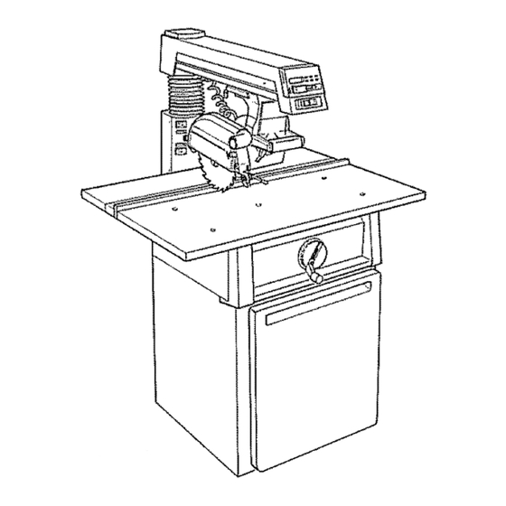
10" ELECTRONIC
RADIAL SAW WITH
23" CABINET AND
1 DOOR
10" ELECTRONIC
RADIAL SAW WITH
LEG SET
Serial
Number
Model and serial numbers
may be found at the rear of
the base
You should record both
model and serial number in
a safe place for future use,
CAUTION:
READ ALL
INSTRUCTIONS
CAREFULLY
113°198211_\
113o19825t
10-.INCH ELECTRONUC
RADIAL SAW
® Assembly
® Operating
® Repair parts
Sold by SEARS, ROEBUCK AND CO., Chicago,
JL. 60684 U.S.A.
Part No, SP5102
Printed in U,S,A
Advertisement
Table of Contents
Troubleshooting

Related Manuals for Craftsman 113.198251


Summary of Contents for Craftsman 113.198251
- Page 1 SaveThisManual ForFuture Reference 10" ELECTRONIC 113°198211_\ RADIAL SAW WITH 23" CABINET AND 1 DOOR 10" ELECTRONIC RADIAL SAW WITH 113o19825t LEG SET Serial Number Model and serial numbers may be found at the rear of the base You should record both model and serial number in 10-.INCH ELECTRONUC a safe place for future use,...
- Page 2 FULLONEYEAR WARRANTY O NCRAFTSMAN RADIALSAW !t within one year from the date of purchase, this Craftsman Radial Saw fails due to a defect in material or workmanship, Sears wilt repair it, free of charge. WARRANTY SERVICE IS AVAILABLE BY SIMPLY...
- Page 3 Safety Information ...... The operator's manual contains safety infor- Major Hazards mation, instructions and signs for your protec- tion against serious injuries, including: 1. Workpiece Kickback I_x)ssof fingers, hand, arm or leg from contact Kickback is an uncontrolled grabbing and with the saw blade.
- Page 4 3. Wrong Way Feed Wrong way feed is feeding the workpiece into the end of the saw with the anti-kickback pawls_ The worl_iece can be grabbed by the blade and pull your hands into the blade before you can let go or pull back. Fingers, hand or arm carl be cut off°...
- Page 5 Personal Safety Saw Safety L Wear safety goggles labeled "ANSI Z87A" !. Keep guards and anti-kickback pawls in on the package. Do not wear regular glasses, place and in working order. they are not safety glasses. 2. Check for broken or damaged parts before 2.
- Page 6 14. Rip workpieces that are longer than the Safety Labels on the Radial Arm Saw diameter of the blade being used. Do not rip The following labels are on your radial arm a workpiece that is shorter than the diameter saw.
- Page 7 Putting Your Saw Together ......Your radial arm saw is easy to put together, The following parts are included with model however it will take time. Ask a friend to I13_198211: help, and follow these assembly instructions° It is important for your safety, and for the A Basic Saw Assembly ....
- Page 8 The following parts are included with model 113.198251: MEDIUM SCREWDRIVER Basic Saw Assembly .... Rear Table ....7/16" WRENCH #2 PHILLIPS SCREWDRIVER 112" WRENCH Table Spacer ....3/4" WRENCH Rip Fence ......Front Table ........ Operators Manual ....314" SOCKET 9/16"...
- Page 9 Hex Hd_ Screw 5/16-18 x 3/4 ..BA Yoke Plug ......Washer 11/32 x 7/8 x t/I6 ..Switch ......Lockwasher 5/16 ....... Battery ......Hex Nut 5/16-18 ..... BD Motor Support ....Pan Hd. Screw i/4-20 x 1 ... BE Pan Hd.
- Page 10 BR Hex Hd. Screw 5/16-18 x 3/4 ..Battery Cover _......Handwheel ......BS Washer 11/32 x 7/8 x 1/16 ..Arbor' Wrenches ......B'I Lockwasher 5/16 ....BU Hex Nut 5/16-18 ....BV Pan Hd. Screw t/4-20 x 1 ..BW Washer 17/64 x 5/8 x 1/32 ..
- Page 11 t, Turn the shelJ upside down on the floor° 4, As you assemble your radial arm saw, some of the holes in the parts will line up and The wide edge should point down, and the others will not, This happens because some three narrow...
- Page 12 1 t_ Put two truss head bolts through right 6. Put the casters (wheels) on the shelf and side panel and spacer, one on each side. shelfstiffenero Since the shelf is upside down, the wheels will point up o Line up four holes 12.
- Page 13 Corner Brackets 21, Use eight truss head bolts, lockwashers, Shelf and hex nuts to hold the skirts in place. Hand- tighten. (Figure 21) Put a truss head bolt through the hole at the back, right corner of the shelf, This hole goes through the shelf and the right side panel.
- Page 14 35. Adjust the lower' nut with the 9/16 inch Put a lockwasher and hex nut on the bolt wrench until the leveling foot is at the desired and tighten using a 7/16 inch wrench height° socket. 36. Tighten the top nut by hand, 27°...
- Page 15 Building the Leg Set The following parts are used in the Leg Set Assembly. Legs ........Upper Stiffeners ....... Lower Stiffeners ....... Fig° 27 - Pan Head Screw 3. Attach the door to the hinges on the side panel using four plastite screws, Tighten with...
- Page 16 6. Put another' hex nut on each of the leveling 10. Adjust the lower nut with the 9/16 inch wrench until the leveling foot is at the desired feet and hand-tighten until they are against height. the leg_ Upper Stiffener 11.
- Page 17 Mounting the Motor 8o Slide the bevel encoder to the top center position so it will fit into the notch on the Both Models motor support bracket. (Figure _WARNING: Plugging the saw in dur- 9. Slide the motor onto the motorpivot sup- ing assembly can result in electrical port_ Make sure the motor...
- Page 18 Attaching Trim Ledge and 13o Repeat steps 10-11 until the bevel lock Trim Caps wilt not touch the left side of the ,yoke, and the gap is not more than 1/16 inch_ Both Models 14. Lock the bevel lock. 1. Hold the trim ledge against the front of the 15.
- Page 19 Location and Function of Controls I,II,l,ll,, 113 198211 Fig_42 - Radial Saw Controls On/Off Switch WARNING: The saw can start ac- cidentally or be used by children and others when the yellow key is left in the The on/off switch turns the power to the saw on and off.
- Page 20 Bevel Lock The bevel lock is used to hold the blade at various angles to the table. To unlock the bevel lock, move the lock to the right. Always hold the motor when you unlock the bevel lock. (Figure 46_ ,_k CAUTION: The motor is heavy and can swing clown quickly.
- Page 21 There are five pre-set bevel angles at -90 °, swivel lock when the motor is in one of these -45 °, 0°, 45°, and 90°. To unlock the bevel positions, stand facing the saw handle, puI! lock when the blade is at one of these angles, the swivel lock all the way toward you, and move the bevel lock all the way to the right turn the motor as you hold the lock in this...
- Page 22 Handwheel The handwheel controls the height of the radial arm. To raise the radial arm, turn the handwheel clocle, vise. To lower the radial arm, turn the handwheeI counterclockwise. (Figure Fig. 52 - Handwheel One complete turn of the handwheel moves the arm 1/16 inch.
- Page 23 The blade of your radial arm saw must be 1. Loosen the four screws in the front of the aligned properly for two reasons: to make cohmm support. (Figure 53) cuts accurate, and to prevent binding of the blade and workpiece which can cause jams or thrown workpieces.
- Page 24 Leveling Table Supports 1o Raise the radial arm until the bottom of 6. Turn the motor' until the arbor shaft is the motor is about 2-1/2 inches above the pointing straight down toward the saw° (Figure 56) saw, 2. Locate four hex head bolts and put a flat £...
- Page 25 If the arbor wrench will not fit between arbor shaft and the table support at any point, repeat steps 8-21 until the table supports level, or If there is a gap between the arbor wrench and the arbor shaft at any point, repeat steps 8-2t until the table supports are level.
- Page 26 Mounting the Front Table 1_ Make sure that thefi"ont table is upside down. 2_ Place a tee nut over' the leveling hole and hammer it into place_ (Figures 59 & 59A) Bolt Tee Nut ---..,-_, ._,) Fig,, 61 Fig..59 5. Start the cup point set screw through leveling hole.
- Page 27 8. Install the pan head bolts through 13. If there is a gap larger' than 1/32 inch, go other four mounting holes, Put a tockwasher back to step 11 and repeat, or and hex nut on each bolt and tighten using a Phillips screwdriver_...
- Page 28 Squaring Crosscut Travel CAUTION: Overtightening the arbor nuts may cause the blade collars to warp and the blade to wobble while cut- The blade must travel perpendicular to the ting. Use the arbor wrenches to tighten fence along the radial arm in order for cross- the arbor nuts but do not overtighten.
- Page 29 If the blade tried to "walk" on the square, tighten the top left screw to move the aHn to the right+ Then tighten the top right screw to meet the column_ Go to step 14 Move the motor back and forth along the radial arm.
- Page 30 If there is a gap between the square and the 22° Lock the rip lock, put the spacer, fence the blade after any rotation (Figure 73), go and rear table back in place, lock the table to step 6. clamp, and go to the next section.
- Page 31 9. Hold the motor tightly and lock the bevel 17. Turn the blade with your hand several lock. Do not let the motor move out of place. times and check to see if the square is flush with the blade. 10.
- Page 32 4. Turn the blade with your hand several times and check to see if the square is flush with the blade. 5. If the square is flush with the blade after each rotation, no change is needed. (Figure 77) Go to the next section, or If there is a gap between the square and the blade after any rotation, go to step 6.
- Page 33 Squaring Blade to Table for 4. Turn the blade With your hand several times and check to see if the square is flush Ripping with the blade. 1. Unlock the swive! lock and turn the motor 5. If the square is flush with the blade after to the out-rip position...
- Page 34 hand. Try to keep the carriage bearing from 7. Hold the square in place and use the 9/16 turning. inch wrench to turn the bolt until the square is flush with the blade. 15. If you can keep either of the carriage bear- ings fiom turning while the motor moves 8.
- Page 35 Making Blade Parallel to Table These steps are done to help prevent the workpiece from being thrown or damaged when the saw is used for edging. Fig,85 & Lower the radial arm until the blade just rests on the edge of the framing square, Make sure that the square is on the blade and not on the set of a tooth.
- Page 36 9. Unlock the bevel lock. 16. Turn the blade with your hand several times and check to see if the square is flush 10. Loosen the two screws on the back of the with the blade. motorsuppo,¢ using a 1/8 inch hex-L wrench and pliers if necessary.
- Page 37 WARNING: Kickback can occur if 3. Make sure that the lower edge of the guard the spreader is not in line with the is parallel to the table. (Figure blade. You can be injured or killed. ways adjust the spreader and make sure 4.
- Page 38 13. Loosen both nuts Oll the spreader using a 1/2 inch wrench. 14. Slide the spreader with your hand until it is against the fence directly behind the blade. 15. Tighten both nuts using a 1/2 inch Antikickback Pawls wrench° Do not move the spreader as you tighten these nuts.
- Page 39 Digital Display ELEV: This button displays the height of the blade. The "0" display is usually set whh the blade just touching the table. A positive dis- play shows the distance the blade has been CRAF NAN raised above "0". A negative display shows the distance the blade has been lowered...
- Page 40 5. If there is still no display, contact your Installing the Battery nearest Sears store, or !. Slide the battery into the opening behind If the display says: the digital display with the angled corner on top. (Figure 95) go to step 6. Battery 6.
- Page 41 6. Unlock the miter lock. 7. Move the arm to the right until it snaps into the 45 ° position. 8. Lock the miter lock. 9. The display should say: .J.u _=- p 10. Unlock the miter lock. 11. Move the a_rn to the left until it snaps into the -45°position.
- Page 42 Bevel Eneoder 14. If the display is correct at all three points, go to the next section, or 1. Push the ON/OFF button to turn the dis- play on. If the display is not correct at one or more of these points, go to step 15.
- Page 43 8. Push the ELEVbutton. 22. If the display is still not correct, repeat steps 15 - 21 until the bevel encoder is in the 9. Push the REF SET button. right position, 10. The display will say: If the display is correct, go to the next section.
- Page 44 go to the next section, or 8. Lock the rip lock. 9. Push the RIP button. If the display says: 10. If the display shows the O-RIP flanction, go to step 11, or If the display shows the RIP function, push push the REF SET button again, Then go to...
- Page 45 E ectrical Connections _.'n ..WARNING: To avoid shock or fire, if Motor Specifications power cord is worn, cut_ or damaged any way have it replaced immediately. The AC motor used in this saw is a capacitor- start, non-reversible type having the following Your unit is wired for 120V it has a plug specifications: that looks like the one shown...
- Page 46 Extension Cords WARNING: To maintain proper tool grounding, whenever the outlet you The use of any extension cord will cause are planning to use for this power tool some loss of power. Use the following table is of the two prong type do not remove to determine the minimum wire size or alter the grounding prong in any man-...
- Page 47 Crosscutting Crosscutting is used to cut a workpiece to length. The workpiece is held against the fence. The saw' blade is pulled through the workpiece. Cuts are usually made across the grain of the workpiece. Types of Crosscuts The basic types of crosscuts are shown below. Notice the hand and body position in each.
- Page 48 4. Fingers or hand can slip into the saw Safety Information blade as you make a crosscut. Fingers, Crosscutting hand or arm can be cut off. Keep the hand holding the workpiece at least 8 in- Read and follow the safety information below ches to the side of the workpiece, out of before maldng any type of crosscut.
- Page 49 10. The workpiece cannot be controlled Blade Guard, Anti-Kickback or held stable enough to do free hand Pawls and Spreader cutting. The workpiece can be thrown or slip and pull fingers and hand into the The blade guard, anti-kickback pawls and saw blade.
- Page 50 Crosscutting Checklist Cutting Table and Fence Kerfs Use the following checklist at the beginning You will need to cut a new table kerf (shal- of each new cutting period to reduce the risk low cut) and fence kerf (slot left in the fence of an accident.
- Page 51 A_, WARNING: The saw blade will sud- 8. Grasp saw handle and hold your forearm in line with the saw handle as shown below. denly come toward you when lowered into the table if the rip lock is unlocked. Fingers and hand can be cut off. Lock the rip lock before and after each crosscut.
- Page 52 4. Adjust the height of the anti-kickback Making Crosscuts pawls to clear top of fence and workpiece by about 1/8 inch. The pawls and spreader help The following section contains safety i_fforma- provide protection from the leading edge of tion and instructions for making crosscuts.
- Page 53 12. Support and hold the workpiece down Pull the saw blade through and against the fence firmly with your left workpiece to the distance shown below. hand. 13o Pull blade through fence and workpiece ,just enough to complete the cut. Fig 1t2 14o Return saw to its rearmost position...
- Page 54 Ripping is used to change the width of the When to Use In-Rip or Out-Rip workpiece by sawing along its length. The The in-rip saw position provides better workpiece is fed into the saw blade. The visibility of both the workpiece and your' fence is used as a guide.
- Page 55 2. One of the most common and the Safety Information most dangerous mistakes people make Ripping is to reach for the workpiece at the out- feed side of the saw. DON'T ! The Read and follow the safety information below workpiece could kickback...
- Page 56 4. Non-thru cuts increase the chance of 2. The workpiece can be grabbed by the kickback because the anti-kickback saw blade and take off like a missile. pawls cannot always grab the irregular Anyone standing in the path of the workpiece surface.
- Page 57 Rip Cutting Checklist Blade Guard, Anfi-ldckback Pawls and Spreader Use the following rip cutting checklist at the The blade guard, anti-kickback pawls and beginning of each new cutting period to workpiece spreader are designed to reduce or reduce the risk of an accident. eliminate the risk of injury from blade con- tact, workpiece kickback and wrong way feed°...
- Page 58 Blade Guard Adjustments Making a Rip Cut Table Kerf 1. Unplug saw and remove yellow key. You will need to make a table kerf before a rip cut can be made. Every time you move 2. Put saw in In-Rip position and lock the the blade a new distance...
- Page 59 Making Rip Cuts Anti.kickback Pawls and Spreader Adjust- ments When to Use In-Rip or Out-Rip I. Go to the outfeed end of the saw blade° The in-rip saw position provides better 2. Put edge of worlcpiece beside the blade visibility of both the worlcpiece and your and under the pawls.
- Page 60 _WARNINL_: When making through 9. Stand out of the line of the workpiece to rip cuts do not set the blade closer than be clear of worl_iece in case of kickback. 1/2 inch from the fence or auxiliary fence, your hands will be brought close...
- Page 61 on the arbor could cause the dado and arbor nut to spin off. Take several passes of the dado if cut required is greater than 1.3/16 of an inch wide. 3. To avoid excessive load on the motor never cut a 13/16 inch wide dado deeper than 1/8 inch in one pass.
- Page 62 WARNING: If the auxiliary fence is 3. Remove saw blade, dado, or other acces- not used when the saw arm is in the 0° sory from the saw arbor shaft before using crosscut position, the molding head can- the accessory shaft° Do not use the saw with not be located behind the fence for safe accessories installed on both ends of the saw arbor shaft at the same time.
- Page 63 ,, n, i i, i i I','"IllUI"""'"'M' nuu ..i i, Cutting Accessories Push Stick Fences Push sticks are used during ripping when the Fences are required for all saw operations. blade is placed between 2 and 6 inches from the fence.
- Page 64 Auxiliary Fence and Push Block An auxiliary fence must be used if the blade 3/8" Plywood is positioned between 1/2 inch and 2 inches from the fence during ripping, An auxiliary fence must always be used with a push block. This Face and This Their purpose is to keep your hands away Edge Must Be Parallel...
- Page 65 5. Cut out a notch from the 12 inch side of Auxiliary Fence for Edging the 3/8 plywood that is 9 1/2 inches long by 3/8 inch wide. The dimensions of the remain- Make an auxiliary fence for edging: ing 3/8 plywood are shown in Fig. 165. o before doing edging with the arm at 0°...
- Page 66 Featherboard Featherboards are used during rip cutting to help keep the workpiece against the fence, The featherboard is clamped to the front table, so that the angled edge of the feather- board is against the worlcpiece on the infeed end of the blade, The other edge of the workpiece is against the fence.
- Page 67 *Recommended Accessories Item Cat. No. Lower Retractable Guard Saw blades lower retractable guard which meets (10" diameter with 5/8" hole) See Catalog OSHA requirements for occupational Leg Set Caster 9-22221 or 9-22222 of the radial saw is available. (See Note) 9-25246 Sanding Drum...
- Page 68 ii..ii,m,i ,,wlllw,,,i ,i..i ii,, ....Glossary ..........Anti-kickback Pawls: Pivoted objects with Molding Cut: Non-through cut which teeth which help prevent workpiece kickback. produces a contoured surface on the workpiece_ Arbor: The bar or shaft that holds the saw blade.
- Page 69 ...... ,i,1,,,,i iiii1,,i,, i iii ....Helpful Hints ......3, Place the same edge of the workpiece In order to get accurate cutting results from against the fence for all cuts. Make the your radial arm saw, do the following: first cut at one end of the workpiece, then flip the workpiece over and make...
- Page 70 3. Lock the miter, bevel, or swivel lock. To extend the life of the front table of your saw, tack a piece of 1/4 inch plywood over it. Make sure that the tacks are not in the path of the saw blade. These steps will reduce stress on saw parts, and improve the accuracy of your cuts.
- Page 71 Motor Frequently blowing of fuses or tripping of circuit breakers may result if: To avoid motor damage this motor should be blown out or vacuumed frequently to prevent sawdust buildup which will interfere with o Motor is overloaded: Overloading can oc- normal motor ventilation°...
- Page 72 Your saw is precision built and should be When you receive your new Craftsman radial kept properly lubricated. Before describing saw, it requires no lubrication. The radial the various points which may periodically re- saw has been partially aligned and all bear-...
- Page 73 .Lubricate the cam surfaces of the rip lock assembly+ +A light film of oil should be wiped on the face of the column tube to lubricate the fit between the column tube and column support. With elevation hand- wheel raise ann to upper limit+ Com- pletely collapse bellows by pulling down on top flange as illustrated for ac-...
- Page 74 Swivel Lock Adjustments for Wear Ihis handle provides a fr'iction lock between Bevel Lock the upper face of the yoke and the bottom The purpose of the bevel lock is to lock the t'ace of the carriage. It should eliminate motor at any bevel angle.
- Page 75 Arm and Column With the miter lock unlocked and in the unln- dexed position the arm should fit snugly to the column tube and not allow any vertical movement, if you can move the end of the arm up and down an adjustment is needed_ !.
- Page 76 2_Push the carriage back against the rear stop. 3. Hold the front carriage bearing with your fingers as tight as possible and pull carriage forward at the same time. If you can prevent the bearing from turning an adjustment is re- quired, (Figure 147) Fig 148 - Location of Hex Nut 3.
- Page 77 Rip Lock Miter Lock Handle The n_plock locks the carthage in any position along the length of the ann° If the carriage can be easily moved by pushing and pulling on theyoke handle when the rip lock is in the locked position an adjustment is required.
- Page 78 ..i ..i,,,i iii1,, II"MII' Troubleshooting , qp I ..IllU q ..WARNING: To avoid injury turn power switch off and remove plugfrom power source outlet before troubleshooting. Electronics Problem Probable Cause What to Do Battery not installed correctly. Adjust battery position in com- No display when On/Off partment.
- Page 79 Electronics Problem Probable Cause What to Do Display shows EEE.E Arm or carriage moved Follow procedure for setting rapidly for indicator to monitor, zero reference points in the Set- ting Electronic Display section. Display wii! reset to zero Encoder or indicator display Have electronics checked defective.
- Page 80 Motor - 2 Probable Cause What to Do Problem Reduce the line load, Power line overloaded with Motor fails to develop full lights, appliances, and other power. motors. (Power output of motor decreases rapidly with Undersize wires or circuit too Increase wire sizes, or reduce decrease in voltage at motor terminals.
- Page 81 Saw Operations Problem Probable Cause What to Do Crosscuts not accurate Looseness between column tube Go to Alignment of the Blade, 0° and 45° miter. and column support. Adjusting Elevation. Crosscut travel not square Go to Alignment of the Blade, with fence.
- Page 82 Saw Operations What to Do Problem Probable Cause. Go to Alignment of the Blade, Saw blade not square Workpiece kerr rough with tooth marks from to fence. Squaring Blade to Fence. blade (also called heel). Go to Alignment of the Blade, Saw blade not parallel to table,, Making Blade Parallel to Table.
- Page 83 Saw Operations Problem Probable Cause What to Do IlL, i J,,, ,,, i,,,ll i, Clamping force not suffi- Bevel lock needs adjusting. Go to Maintaining Your Saw, cient at bevel angles other Adjustments for Wear, Bevel than 45° . Lock. Depth of varies from Table top not parallel with arm.
- Page 84 PARTS LIST FOR CRAFTSMAN 10" ELECTRONIC RADIAL MODEL NOS. 113.198211 and 113.198251 (SeeFig 8) (See Fig, 6) (See Fig, 2) Fig. 3 & 4) (See Fig. 5) FIGURE...
- Page 85 PARTS LIST FOR CRAFTSMAN 10" ELECTRONIC RADIAL MODEL NOS. 113.198211 and 113.198251 Always order by Part Number - Not by Key Number FIGURE Part Part Description Description 815989 Clip, "U" 1/4-20 816333 =1 *Screw, Pan Rec.. 815774 Rivet 1/4 x 1/2 Type "TT"...
- Page 86 PARTS LIST FOR CRAFTSMAN 10" ELECTRONIC RADIAL MODEL NOS. 113.198211 and 113.198251 _,23 FIGURE...
- Page 87 PARTS LIST FOR CRAFTSMAN 10" ELECTRONIC RADIAL MODEL NOS. 113.198211 and 113.19825'1 Always order by Part Number - Not by Key Number FIGURE 2 - BASE AND COLUMN ASSEMBLY Part i Key Part iNo. Description Description 815857-1 815707 Handwheel Screw, Hex Washer Hd,...
- Page 88 PARTS LiST FOR CRAFTSMAN 10" ELECTRONIC RADIAL MODEL NOS. 113,198211 and 113.198251 ,,14 MOTOR CORD FIGURIE 3...
- Page 89 PARTS LIST FOR CRAFTSMAN 10" ELECTRONIC RADIAL MODEL NOS. 113.198211 and 113.198251 Always order by Part Number - Not by Key Number FIGURE 3 - YOKE MOTOR ASSEMBLY l ey I Keyl No.I Description Description No.J ,111,111,1, 1815803 20 1815686...
- Page 90 PARTS LIST FOR CRAFTSMAN 10" ELECTRONIC RADIAL MODEL NOS. 113.198211 and 113.198251 19 J"1_ FIGURE...
- Page 91 PARTS LIST FOR CRAFTSMAN 10" ELECTRONIC RADIAL MODEL NOS. 113.19821'1 and 113.198251 Always order by Part Number - Not by Key Number FIGURE 4 - YOKE ASSEMBLY Part Part Description Description STD551131 *Lockwasher, External 5/16 810214_3 Screw, Low Hd 815691...
- Page 92 PARTS LIST FOR CRAFTSMAN 10" ELECTRONIC RADIAL MODEL NOS. 113.198211 and 113.198251 FIGURE...
- Page 93 PARTS LiST FOR CRAFTSMAN 10" ELECTRONIC RADIAL SAW MODEL NOS. 113.198211 and 113.198251 Always order by Part Number - Not by Key Number FIGURE 5 - MOTOR ASSEMBLY Description ..No. 1,100, ..ii1,1 ,i, Housing, Motor *Capacitor STD376116 I 3 164950 Screw, Type "T"...
- Page 94 PARTS LIST FOR CRAFTSMAN 10" ELECTRONIC RADIAL MODEL NOS. 113.198211 and 113.198251 FIGURE...
- Page 95 PARTS LIST FOR CRAFTSMAN 10" ELECTRONIC RADIAL MODEL NOS. 113.198211 and 113.198251 Always order by Part Number - Not by Key Number FIGURE 6 - ARM ASSEMBLY Part KeY I Pall Description Description 816490 815688 Encoder, Rip Arm, Radial 8! 5809...
- Page 96 PARTS LIST FOR CRAFTSMAN 10" ELECTRONIC RADIAL MODEL NOS. 113.198211 and 113.198251 FIGURE 7 - GUARD ASSEMBLY Always order by Part Number - Not by Key Number IKeyj Part Part Description Description I No. I I 1 1816264-1 Guard STD581050...
- Page 97 PARTS LIST FOR CRAFTSMAN 10" ELECTRONIC RADIAL MODEL NOS. 113.198211 and 113.198251 Always order by Part Number - Not by Key Number FIGURE 8 - TABLE ASSEMBLY Description 815794 Table, Rear 815755 Table Spacer 63432 Fence, Rip 815796 Table, Front...
- Page 98 PARTS LIST FOR CRAFTSMAN 10" ELECTRONIC RADIAL MODEL NOS. 113.198211 and 113.198251 Always order by Part Number - Not by Key Number FIGURE 9 - PARTS LIST 23" CABINET (MODEL 113.198211 ONLY) ,,,,, Part Part Description Description i ,i, 805589-5...
- Page 99 PARTS LIST FOR CRAFTSMAN 10" ELECTRONIC RADIAL SAW MODEL NOS. 113.198211 and 113.198251 FIGURE 10 - LEG SET (MODEL 113.198251 ONLY) Always order by Part Number - Not by Key Number Key I Part N°'i Description 8159! 8 Stiffener, 817105...
- Page 100 NOTES...
- Page 101 NOTES...
- Page 102 NOTES...
- Page 103 NOTES...
- Page 104 104NCH ELECTRONIC RADIAL SERVUCE Now that you have purchased your 10-inch electronic radial saw, should a need ever' exist for repair parts or service, simply contact any Sears Service Center and rnostrSears, Roebuck and Co. stores_ Be sure to provide all pertinent facts when you call or visit° MODEL NO.
Need help?
Do you have a question about the 113.198251 and is the answer not in the manual?
Questions and answers