Table of Contents
Advertisement
i
Sears
owners
manual
MODEL NO.
113.19770
SAW ONLY
113.197750
SAW WITH
LEGS
Serial
Number
.
_
Model and serial
number may be found
at the front of the base.
You should
record
both
model
and serial number
in a safe place for
future
use.
CAUTION:
Read
GENERAL
and
ADDITIONAL
SAFETY
INSTRUCTIONS
carefully
Sold
by SEARS,
Part No. 63676
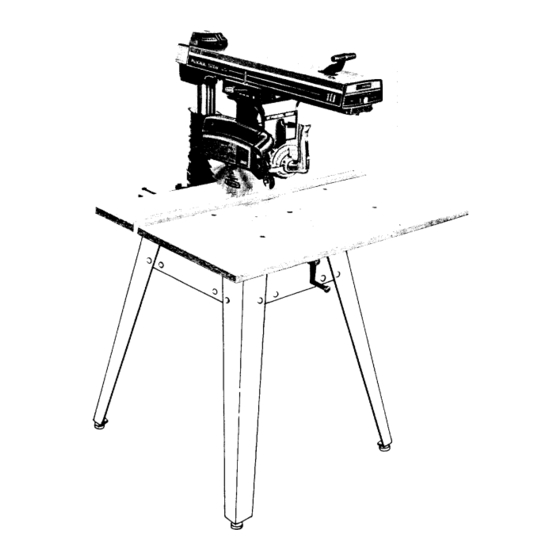
CRRFTSMRNo
IO-INCH
RADIAL
SAW
• assembly
• operating
• repair
parts
ROEBUCK
AND
CO.,
Chicago,
IL. 60684
U.S.A.
Printed irl U.S,A
Advertisement
Table of Contents

Subscribe to Our Youtube Channel
Related Manuals for Craftsman 113.19770


Summary of Contents for Craftsman 113.19770
- Page 1 Sears owners manual MODEL NO. 113.19770 SAW ONLY 113.197750 SAW WITH LEGS Serial Number Model and serial number may be found at the front of the base. You should record both CRRFTSMRNo model and serial number in a safe place for future use.
- Page 2 FULL ONE YEAR WARRANTY ON CRAFTSMAN RADIAL SAWS If within one year from the date of purchase, this Craftsman Radial Saw fails due to a defect in material workmanship, Sears will repair it, free of charge. Warranty service is available...
- Page 3 instructions for radial saws additional safety CAUTION. Always disconnect power cord before - A large proportion of saw accidents"_- caused by-use removing the guard, changing the cutting tool, changing of the wrong type blade, dull, badly set, improperly set-up making adjustments.
- Page 4 additional safety instructions for radial saws removed !rom arbor before using proper set-up and cutting procedures. Do not stand, accessory shaft (rear end of the saw motor). NEVER permit anyone else stand, line with operate tht_ saw with cutting tools (including sanding potential...
- Page 5 WEAR YOUR --,_j, operation power tool result in foreign_ - - _:i i objects being thrown into eyes, which can result severe eye damage. Always wear safety goggles complying i _:,_,i_ with ANSI Z87.1 (shown on Package) before commencing power tool operation.
- Page 6 electrical connections Make certain the receptacle is connected to a 240V power supply through a 240V branch circuit having at least a 15-amp. capacity, and protected a 15-amp. time-delay fuse or circuit breaker. MOTOR SAFETY PROTECTION NOTE: This motor should be blown out, or "vacuumed",...
- Page 7 _." _t ¸ over-heating andmotorburn-out, usethetablebelow to determine theminimum wiresize (A.W.G.) extension cord. Wire Size Requir Z_:_ Length of the (American Wire Gauge ul__m__r) _ '_;'! Useonly 3 wire extension c ordswhichhave3 prong Conductor grounding type plugs and3-pole receptacles which accept 240 Volt Lines I 120 Vo--_-L:_n_;_ ..
- Page 8 CONTENTS Guarantee ........Location and Functions of Controls ....General Safety Instructions for Power Tools ..Basic Saw Operations ......Additional Safety Instructions for Radial Saws ..Adjustments to Compensate for Wear ....Electrical Connections ......Trouble--Shooting ......Assembly and Alignment ......
- Page 9 The following p arts areincluded w ithModel 113.197750. Table Loose Parts Qty. Leg ........Stiffener, L.H......Stiffener, R.H......Loose PartsBagPart No. 63752 (containingthe following items): © - Screw, TrussHd. 1/4-20 x 5/8 ....- Lockwasher, 1 /4 External ....- Lockwasher,5/16 External ....- Nut, Hex 1/4-20 ......
- Page 10 X in top of legs. Install screws, washers and nuts as shown. If you mount the saw on any other Craftsman base or flat bench, make sure Elevation Crank has proper clearance rotate.
- Page 11 assembly and alignment positive switch is "OFF" and power cord unplugged thru-out entire procedure. REMOVE CARRIAGE STOP SCREW, LOCKWASHER LOCKWASHER TAG. Read understand warning before discarding. 1_,_ STOP SCREW HEX "L" WRENCH SUPPLIED LOCK BEFORE PROCEEDING. HOLDING CARRIAGE ASSEMBLY WITH BOTH HANDS, CAREFULLY...
- Page 12 ALIGNMENT PROCEDURE IMPORTANT: SQUARE SCREW s/] 6- ] 8 x 3/4 IN ORDER TO OBTAIN MAXIMUM CUTTING TABLE MOUNTING TABLE MOUNT! ACCURACY, FOLLOWING STEPS SUPPORT CHANNEL SUPPORT CHANNEL MUST CAREFULLY FOLLOWED. BECOME THOROUGHLY FAMILIAR WITH THESE STEPS SO THAT YOU CAN ALWAYS SCREWS MAINTAIN YOUR...
- Page 13 assembly and alignment INSTALLATION OF FRONT (WORK) TABLE. Place front table board upside down on a workbench floor. Drive T-nut into hole that is not counterbored. Align counterbored holes with matching holes support channels. Install five 17/64 inch flat washers, and four ¼- 20 x 1 inch...
- Page 14 Loosen (2) ¼ - 20 Gib set screws on the left side at the rear of the column support. "L" WRENCH Elevate, then lower Arm: if the column binds and elevation is difficult loosen 5/16- plated nuts on front side of the column support until achieve...
- Page 15 assembly alignment ,:i} Lower until saw blade just clears the front table. ! ,iy_i '_ i_i_: ! L_-----J Lock the yoke clamp handle and bevel lock lever. Place a framing square table as shown position the blade and square until the leg of the square just contacts a tooth...
- Page 16 STEP FOUR SQUARING SAW BLADE TO (WORK) TABLE NOTE: If alignment procedure step one was not performed, this adjustment can not be accomplished. Place a framing square on the table with the short against the saw blade. Do not allow the square to rest against...
- Page 17 • assembly and alignment ! "" To correct "heel" condition proceed as follows: Remove left hand carriage cover. HEAD SCREWS Loosen the yoke clamp handle. Loosen (slightly) the two hex-head screws. Rotate yoke assembly until gap between saw blade and square is eliminated, Lock yoke...
- Page 18 STEP SIX SCREW INSTALLING ADJUSTING SCALE INDICATORS. NOTE: The rip scales and pointers are intended be used quick settings. greater accuracy, RIP SCALE take direct measurement between blade and fence. INDICATOR Pre-assemble indicator and twin nut, loosen but do remove the two screws which...
- Page 19 assembly and alignment ALIGNMENT OF SPREADER FOR RIPPING. WARNING: NEVER POSITION GUARD ANTI KICKBACK ASSEMBLY WITH POWER POSITION ANTIKICKBACK PAWLS GRASPING PAWLS OR SPREADER. Install Blade Guard. Sight (visually) check proper alignment spreader with saw blade as shown. If the spreader not aligned, adjust it as follows:...
- Page 20 locations and functions of controls versatility Radial is due, in part, to its controls, and these are the keys to its successful operation. Learn to use the controls all operations before actually starting to saw. A series of six diagrams is located on the top surface of the DEPTH...
- Page 21 Proper Indexing Method Experienced operators bevel lock lever locks motor to the yoke woodworking equipment, such as this Craftsman Radial when motor is in position. Pull lever Saw, acquire habit indexing in one direction release and push to lock.
- Page 22 WARNING: YOUR OWN SAFETY ALWAYS Spreader LOCK SWITCH "OFF" WHEN IS NOT prevent kerf from closing on sawblade IN USE. REMOVE KEEP IT IN A SAFE possible kickback; PLACE . . . ALSO IN THE EVENT OF A POWER FAILURE (ALL YOUR LIGHTS...
- Page 23 HA VE YOU FOLL 0 WED ALL SIX STEPS ALIGNMENT PROCEDURE? IF YOU HAVE FOLLOWED THEM IN THEIR PROPER SEQUENCE, CANNOT EXPECT ACCURATE CUTTING RESULTS. L ....THIS EDGE OF BOARD AGAINST FENCE FOR ALL CUTS FENCE In addition proper alignment your saw,...
- Page 24 basic saw operations REQUIREMENTS FOR CROSSCUT Board position (s_ationary) against fence (guide) laying flat on table top. (OPERATIONS 1 THROUGH Arbor must be tight and saw blade guard installed in horizontal position. Arm control lever must be in locked position. Adjust the antikickback assembly...
- Page 25 basic saw operations OPERATION No. 2 - MITER CROSSCUT Miter crosscutting is the process of sawing a board at any angle other than a 90 ° (square) cut. The 45 ° miter angle is a popular one, since boards 45 ° assembled to form a 90 °...
- Page 26 REQUIREMENTS WHEN RIPPING (OPERATIONS 5 AND 6) Carriage lock knob must be locked. Radial arm must be locked in 0 ° position. Guard spreader and antikickback mechanism must properly set. OBSERVE INSTRUCTIONS PARAGRAPH, "POSITIONING GUARD, WorkfeedingmUstthrough.be held firmly against table and fence , HGAR NAT]ErR4...
- Page 27 Since the work is pushed along the fence, it must have a straight edge n order to make sliding contact with fence. Also, the work must make solid contact with table, so that it will not wobble. Provide a straight edge, even t this...
- Page 28 adjustments to compensate for wear ADJUSTING BEVEL LOCK LEVER purpose of this lever is to lock the motor at any angle. To adjust, remove the set screw with wrench shown. Use the bevel lock lever as a wrench to tighten clamp bolt.
- Page 29 adjustments to compensate for wear 3,/8-16 BOLTS TO COLUMN With control lever unlocked index release position, the arm should move firmly with vertical play in the arm. The arm should snugly on the column. If not, then adjust. Remove (2) screws from rear cover...
- Page 30 LOCK ADJUSTING WHEEL control lever operates a brake shoe that locks _eleases the arm, and automatically releases the arm index pin for 0 ° & 45 ° miter settings. The lock action should feel tight and secure. Considerable amount of effort must be applied to the lever to lock...
- Page 31 ..__.:,trouhle-shootinn c_41SH FINISH CUT END SQUARE SQUARE WARNING: REMOVE POWER CORD FROM POWER SOURCE BEFORE TROUBLE SHOOTING. NOTE: Changing one adjustment will effect another, so it is best perform alignment procedures when correcting any one problem. usual operating "troubles" are listed in the following paragraphs with...
- Page 32 trouble-shooting RiP POSITION WOOD BINDS, SMOKES MOTOR SLOWS VIE,,V 'filTH 90 ° TO THE FENCE DOWN OR STOPS WHEN RIPPING. Dull blade or warped board. FENCE Sharpen replace blade. Avoid attempted use of severly warped material. DIRECTION Feed rate too fast. FEED Slow Feed Rate.
- Page 33 MOTOR TROUBLE - SHOOTING CHART NOTE: Motors used on wood-working tools are particularly susceptible to the accumulation of sawdust and wood chips should be blown "vacuumed" frequently prevent interference with normal motor ventilation. TROUBLE PROBABLE CAUSE SUGGESTED REMEDY Motor will not run. 1.
- Page 34 OUTLET BEFORE MAINTAINING LUBRICATING YOUR SAW. Do not lubricate between radial arm cap and radial arm. When receive your Craftsman radial saw, requires no lubrication. radial has been partially PERIODICALLY LUBRICATE THESE POINTS aligned and all bearings are lubricated and sealed for life.
- Page 35 PARTS LIST FOR CRAFTSMAN 10-INCH RADIAL MODEL 113.197750 FIGURE 1 -- LEG SET Part Description 63749 60314 Screw, Truss Hd. 1/4-20 x 5/8 63751 Stiffener, R.H. 63750 Stiffener, L.H. STD 551225 *Lockwasher, External STD 541025 *Nut, Hex 1/4-20...
- Page 36 Figur e 2...
- Page 37 PARTS LIST FOR CRAFTSMAN 10-1NCH RADIAL 11.---------,'_ MODEL NUMBER 113.19770 113.197750 9 ''---'-_<_'" "' \ "oi,/ ¢e //34 28 29 oAny attempt to repair this motor may create a HAZARD 52 51 !mless repair is done by a qualified service...
- Page 38 PARTS LIST FOR CRAFTSMAN 10-INCH RADIAL MODEL NUMBER 113.19770 AND 113.197750 Always order by Part Number- Not by Key Number. FIGURE 2 Part Part Description Description 63518 Cord, with Plug STD 551025 *Washer, 17/64 x 5/8 x 1/32 37818 Relief,...
- Page 39 PARTS LIST FOR CRAFTSMAN 10-INCH RADIAL MODEL NUMBER 113.19770 AND 113.197750 FIGURE YOKE ASSEMBLY Part Part Description Description STD 601105 STD 551037 *Screw, Type "T" Pan Hd. !0-32 x 1/2 *Washer, .380 x 47/64 x 1/16 63661 63652 Cover, L. H. Carriage...
- Page 40 .b,, Figure 4...
- Page 41 PARTS LIST FOR CRAFTSMAN 10-INCH RADIAL MODEL NUMBER 113.19770 AND 113.197750 FIGURE 4 - BASE ASSEMBLY Part Part Description Description STD 503705 *Screw, Soc. Set 3/8-16 x 1/2 STD 580014 *Key, Woodruff 1/8 x 1/2 63623 Latch, 63619 Support, R. H.
- Page 42 PARTS LIST FOR CRAFTSMAN 10-INCH RADIAL MODEL NUMBER 113.19770 AND 113.197750 FIGURE 5 -- ARM ASSEMBLY Part Part Description Description 63626 63637 Housing, 63629 63636 Pin, Arm Index Pin, Clevis 63631 63667 Shoe, Arm Lock Clamp, Cord 63628...
- Page 43 PARTS LIST FOR CRAFTSMAN 10-INCH RADIAL MODEL NUMBER 113.19770 AND 113.197750 10 12 FIGURE 6 - GUARD ASSEMBLY Part Part Description Description 63681 Guard 63271 Paw!, Anti-Kickback 120399 !*Nut, Square, 5/16-18 STD 582043 *Ring, Retaining 7/16 63541 63270 Bar, Antikickback...
- Page 44 Sears owners IO-INCH RADIAL SAW manual SERVICE that have purchased your 10-inch radial saw, should need ever exist repair parts or service, simply contact Sears Service Center most Sears, Roebuck and Co. stores. Be sure to provide all pertinent facts when call or visit.
Need help?
Do you have a question about the 113.19770 and is the answer not in the manual?
Questions and answers
where are the instructions for replacing the HIGH TEMERATURE CUTOFF SWITCH?