Table of Contents
Advertisement
Quick Links
Sears
owners
manual
MODEL NO.
113.19760
Serial
Number
Model and serial
number may be found
at the front of the base.
You
should
record
both
model
and serial
number
in a safe place for
future
use.
CAUTION:
Read
GENERAL
and
ADDITIONAL
SAFETY
INSTRUCTIONS
carefully
CRRFTSMRNo
IO-INCH
RADIAL
SAW
• assembly
• operating
• repair
parts
Sold
by SEARS,
ROEBUCK
AND
CO.,
Chicago,
IL. 60684
U.S.A.
Part No. 6.'4722
Printed in U.S.A.
Advertisement
Table of Contents
Troubleshooting

Subscribe to Our Youtube Channel
Related Manuals for Craftsman 113.19760


Summary of Contents for Craftsman 113.19760
- Page 1 Sears owners manual MODEL NO. 113.19760 Serial Number Model and serial number may be found at the front of the base. should record both CRRFTSMRNo model and serial number in a safe place for future use. IO-INCH CAUTION: RADIAL Read GENERAL ADDITIONAL •...
- Page 2 FULL ONE YEAR WARRANTY ON CRAFTSMAN RADIAL SAWS If within one year from the date of purchase, this Craftsman Radial Saw fails due to a defect in material workmanship, Sears will repair it, free of charge. Warranty service is available...
- Page 3 additional safety instructions for radial saws large proportion of saw accidents is caused by use CAUTION: Always disconnect power cord before of the wrong type blade, dull, badly set, improperly removing the guard, changing the cutting tool, changing the sharpened cutting tools, by gum or resin adhering...
- Page 4 instructions for radial saws additional safety removed from arbor before using proper set-up and cutting procedures. Do not stand, accessory shaft (rear end of the saw motor). NEVER permit anyone else stand, line with operate the saw with cutting tools (including sanding potential...
- Page 5 WEAR YOUR operation power tool result in foreign objects being thrown into eyes, which result severe eye damage. Always wear safety goggles complying with ANSI Z87.1 (shown on Package) before commencing power tool operation. Safety Goggles are available at Sears retail or catalog stores.
- Page 6 electrical connections WIRE SIZES Frequent opening of fuses or circuit breakers may result if motor is overloaded, or if the motor circuit is fused use of extension cord will cause some loss of differently from recommendations. Overloading power. keep this a minimum prevent occur...
- Page 7 LOCATIONS AND FUNCTIONS OF CONTROLS MITER INDICATOR CONTROL LEVER BEVEL INDEX LEVER RiP SCALE INDICATOR SWIVEL ON-OFF LATCH LEVER SWITCH WITH LOCK JSTING WHEEL TABLE CLAMP GUARD CLAMP SCREW ELEVATION CRANK CARRIAGE LOCK KNOB 'OKE LOCK HANDLE MANUAL BRAKE ANTIKICKBACK, SPREADER ADJUSTING WING...
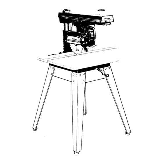
- Page 8 REMAIN (Fig. 1) Table of Loose Parts Qty. UNPLUGGED WHENEVER WORKING Basic Saw assembly ...... THE SAW. Rear table ......Your Craftsman 10-inch Radial is shipped complete Rip fence ......one carton. Steel Legs is an optional accessory. Front table ......
- Page 9 REMOVE SKIDS FROM BASE MOUNT SAW TO CRAFTSMAN BASE, STEEL LEGS, OR FLAT BENCH Make sure Elevation Crank has proper clearance to rotate. saw must be bolted down. Position your saw to slope slightly rearward, so when the carriage is installed...
- Page 10 assembly and alignment positive switch is "OFF" and power cord unplugged thru-out entire procedure. WARN INS REMOVE CARRIAGE STOP SCREW, LOCKWASHER TAG. Read understand warning before discarding. LOCK ARM BEFORE PROCEEDING. HOLDING CARRIAGE ASSEMBLY WITH BOTH HANDS, CAREFULLY START SLIDE CARRIAGE ONTO TRACKS.
- Page 11 ALIGNMENT PROCEDURE IMPORTANT: SQUARE SCREW s/16-18 x 314 IN ORDER TO OBTAIN MAXIMUM CUTTING TABLE MOUNTING TABLE MOUNT! SUPPORT CHANNEL ACCURACY, FOLLOWING STEPS SUPPORT CHANNEL MUST CAREFULLY FOLLOWED. BECOME THOROUGHLY FAMILIAR WITH THESE STEPS SO THAT YOU CAN ALWAYS SCREWS MAINTAIN YOUR PROPER...
- Page 12 assembly and alignment FRONT fABLE HOLE TABLE BOTTOM SIDE UPSIDE DOWN POSITION) HOLD DO'NN SCREWS T-NUT TABLE INSTALLATION OF FRONT (WORK) TABLE. T-NUT (TYPICAL) Place front table board upside down on a workbench floor. Drive T-nut into hole that is not counterbored.
- Page 13 -> Loosen (2) ¼ - 20 Gib set screws on the left side at the rear of the column support. Elevate, and then lower Arm: (a) if the column binds and elevation is difficult loosen 5/16- plated nuts on front side of the column support until...
- Page 14 assembly and alignment Lower until blade just clears the front table. Lock the yoke clamp handle and bevel lock lever. Place a framing square table as shown position the blade and square until the leg of the square just contacts a tooth of the blade.
- Page 15 STEP FOUR SQUARING SAW BLADE TO (WORK) TABLE NOTE: If alignment procedure step one was not performed, this adjustment can not be accomplished. Place a framing square on the table with the short against the saw blade. Do not allow the square to rest against...
- Page 16 assembly and alignment correct "heel" condition proceed as follows: Remove left hand carriage cover. Loosen the yoke clamp handle. HEX HEAD SCREWS Loosen (slightly) the two hex-head screws. Rotate yoke assembly until gap between saw blade and square is eliminated. Lock yoke clamp...
- Page 17 SCREW STEP SiX INSTALLING ADJUSTING SCALE INDICATORS. NOTE: rip scale and pointer is intended to be RIP SCALE used for quick settings. For greater accuracy, take INDICATOR direct measurement between blade and fence. Pre-assemble indicator and twin nut, loosen but do remove the two screws which...
- Page 18 assembly and alignment ALIGNMENT OF SPREADER RIPPING. WARNING: NEVER POSITION GUARD ANTIKICKBACK ASSEMBLY WITH POWER POSITION ANTIKICKBACK PAWLS GRASPING PAWLS OR SPREADER. Install Blade Guard. Sight (visually) to check proper alignment spreader with saw blade as shown. If the spreader not aligned, adjust it as follows:...
- Page 19 locations and functions of controls versatility Radial is due, part, controls, and these are the keys to its successful operation. Learn to use the controls for all operations before actually starting to saw. A series of six diagrams is located on the top surface of the arm.
- Page 20 Proper Indexing Method Experienced operators bevel lock lever locks the motor to the yoke woodworking equipment, such as this Craftsman Radial when motor is in any position. Pull lever Saw, acquire habit indexing in one direction release and push to lock.
- Page 21 WARNING: YOUR OWN SAFETY ALWAYS The antikickback and spreader assembly is used during LOCK SWITCH "OFF" WHEN IS NOT ripping operations is adjustable accommodate IN USE. REMOVE KEEP IT IN A SAFE the thickness of the board being ripped. A wing screw PLACE .
- Page 22 HA VE YO U FOL L 0 WED A L L SIX S TEPS 0 F ALIGNMENT PROCEDURE? IF YOU HAVE FOLLOWED THEM IN THEIR PROPER SEQUENCE, CANNOT EXPECT A CCURA TE CUTTING RESUL TS. THIS EDGE OF BOARD AGAINST FENCE FOR ALL CUTS FENCE _, addition...
- Page 23 basic saw operations REQUIREMENTS FOR CROSSCUT Board position (stationary) against rip fence (guide) laying flat on table top. (OPERATIONS 1 THROUGH Arbor must be tight and saw blade guard installed in horizontal position. Arm control lever must be in locked position.
- Page 24 basic saw operations OPERATION No. 2 - MITER CROSSCUT Miter crosscutting is the process of sawing a board at any angle other than a 90 ° (square) cut. The 45 ° miter angle is a popular one, since boards 45 ° assembled to form a 90 °...
- Page 25 REQUIREMENTS WHEN RIPPING (OPERATIONS 5 AND 6) Carriage lock knob must be locked. Radial arm must be locked in 0 ° position. Work must be held firmly against table and fence while feeding through. Guard spreader and antikickback mechanism must be properly set.
- Page 26 Since the work is pushed along the fence, it must have a straight edge in order to make sliding contact with fence. Also, the work must make solid contact with table, so that it will not wobble. Provide a straight edge, even if this...
- Page 27 adjustments to compensate for wear ADJUSTING BEVEL LOCK LEVER The purpose of this lever is to lock the motor at any angle. To adjust, remove the set screw with wrench shown. Use the bevel lock lever as a wrench to tighten clamp bolt.
- Page 28 adjustments to compensate for wear 3/8-16 BOLTS TO COLUMN With control lever unlocked index release position, the arm should move firmly with vertical play in the arm. The arm should snugly on the column. If not, then © adjust. Remove four (4) screws from...
- Page 29 LOCK ADJUSTING WHEEL control lever operates a brake shoe that locks releases the arm, and automatically releases the arm index pin for 0 ° & 45 ° miter settings. lock action should feel tight and secure. Considerable amount of effort must be applied to the lever to lock arm.
- Page 30 trouble-shooting FINISH CUT END SQUARE SQUARE WARNING: REMOVE POWER CORD FROM POWER SOURCE BEFORE TROUBLE SHOOTING. NOTE: Changing one adjustment will effect another, so it is best perform alignment procedures when correcting any one problem. The usual operating "troubles" are listed in the following paragraphs with...
- Page 31 trouble-shooting RIP POSITION WOOD BINDS, SMOKES MOTOR SLOWS VIEW WITH 90 c THE FENCE DOWN OR STOPS WHEN RIPPING. Dull blade or warped board. Sharpen replace blade. Avoid FENCE F[NC[ _'''_ attempted use of severly warped material. DIRECTION Feed rate too fast. FEED Slow Feed Rate.
- Page 32 MOTOR TROUBLE - SHOOTING CHART NOTE: Motors used on wood-working tools are particularly susceptible to the accumulation of sawdust and wood chips and should be blown "vacuumed" frequently prevent interference with normal motor ventilation. TROUBLE PROBABLE CAUSE SUGGESTED REMEDY Motor will not run.
- Page 33 OUTLET BEFORE MAINTAINING LUBRICATING Do not lubricate between radial arm cap and radial arm. YOUR SAW. When receive your Craftsman radial saw, PERIODICALLY LUBRICATE THESE POINTS requires no lubrication. radial saw has been partially aligned and all bearings are lubricated and sealed for life.
- Page 34 _ _' \ / / / / / / / figur e 1...
- Page 35 PARTS LIST FOR CRAFTSMAN 10-INCH RADIAL MODEL NUMBER 113.19760 Always order by Part Number -- Not by Key Number. FIGURE Part Part Description Description 63518 Cord, with Plug 37384 Nut, Tee 37818 Relief, Strain 37530 Nut, "U" Clip 60339 *Screw, Hex Hd.
- Page 36 PARTS LIST FOR CRAFTSMAN 10-INCH RADIAL MODEL NUMBER 113.19760 "0 45 37 28 29 Figure 2...
- Page 37 PARTS LIST FOR CRAFTSMAN 10-INCH RADIAL MODEL NUMBER 113.19760 FIGURE 2- YOKE ASSEMBLY Part Part Description Description STD 601105 STD 541411 *Screw, Type "T" Pan Hd. 10-32 x 1/2 *Nut, Lock 3/8-16 63661 STD 551037 Cover, L.H. Carriage *Washer, .380 x 47/64...
- Page 38 PARTS LIST FOR CRAFTSMAN 10-INCH RADIAL MODEL NUMBER 113.19760 "0 mmli "11 "0 39 33 Figure...
- Page 39 PARTS LIST FOR CRAFTSMAN 10-INCH RADIAL MODEL NUMBER 113.19760 FIGURE 3 - BASE ASSEMBLY Part Part Description Description STD 503705 STD541450 *Screw, Soc. Set 3/8-16 x 1/2 *Nut, Lock 1/2-13 63623 Latch, STD 580014 *Key, Woodruff 1/8 x 1/2 60330...
- Page 40 PARTS LIST FOR CRAFTSMAN 10-INCH RADIAL MODEL NUMBER 113.19760 111" IF THIS PART REMOVED, DISCARD REPLACE WITH PUSH NUT. FIGURE ARM ASSEMBLY Part Part Description Description 63626 63636 Housing, Pin, Clevis 63667 63629 Clamp, Cord Pin, Arm Index...
- Page 41 PARTS LIST FOR CRAFTSMAN 10-INCH RADIAL MODEL NUMBER 113.19760 15 14 10 12 11 FIGURE 5 - GUARD ASSEMBLY Part Part Description Description 63681 Guard 63271 Pawl, Anti Kickback 120399 STD 582043 *Nut, Square, 5/16-18 *Ring, Retaining 7/16 63541 63270...
- Page 42 NOTES...
- Page 43 NOTES...
- Page 44 Sears owners IO-INCH RADIAL SAW manual SERVICE that have purchased your lO-inch radial saw, should need ever exist repair parts or service, simply contact Sears Service Center most Sears, Roebuck Co. stores. Be sure to provide all pertinent facts when you call or visit.
Need help?
Do you have a question about the 113.19760 and is the answer not in the manual?
Questions and answers