
Related Manuals for Xantrex GRIB and Ethernet interface


Summary of Contents for Xantrex GRIB and Ethernet interface
-
Page 1: Power Supplies
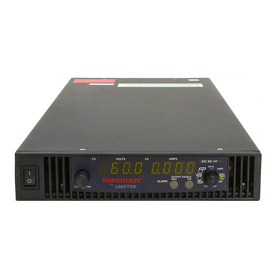
GPIB ENET Operating Manual GPIB and Ethernet Interface for XG Series Programmable DC Power Supplies www.programmablepower.com... - Page 3 XG 850 Watt Series Programmable DC Power Supply Operating Manual...
- Page 4 About Xantrex Xantrex Technology Inc. is a world-leading supplier of advanced power electronics and controls with products from small mobile units to utility-scale systems for wind, solar, batteries, fuel cells, microturbines, and backup power applications in both grid-connected and stand-alone systems. Xantrex products include inverters, battery chargers, programmable power supplies, and variable speed drives that convert, supply, control, clean, and distribute electrical power.
- Page 5 Product Numbers (FGAs) XG6-110 XG60-14 XG8-100 XG80-10.5 XG12-70 XG100-8.5 XG20-42 XG150-5.6 XG33-25 XG300-2.8 XG40-21 XG600-1.4 Part Numbers for Rack Mount Kits Rack Mount Kit Part Number Dual XG 850 Watt RM-D-XG1 Single XG 850 Watt RM-S-XG1 Rack mount rails for RM-XG XG Series Contact Information...
-
Page 7: About This Manual
About This Manual Purpose This Operating Manual provides explanations and procedures for programming the XG 850 Watt Series Programmable DC Power Supply from the GPIB interface and connecting and configuring the power supply to the Ethernet. Scope The Manual covers the GPIB and Ethernet interface options only. Refer to the XG 850 Watt Series Programmable DC Power Supply Operating Manual (Part number: M370078-01) for installation, operating procedures, setup, calibration and troubleshooting for your power supply. -
Page 8: Related Information
Reference Guide (Part number: M370078-04). This document is included with your power supply and provides a quick start on using the front panel interface. More information about Xantrex Technology Inc. as well as its products and services is available at www.programmablepower.com. M370078-06... -
Page 9: Important Safety Instructions
Important Safety Instructions WARNING: High Energy and High Voltage Exercise caution when using a power supply. High energy levels can be stored at the output voltage terminals on a power supply in normal operation. In addition, potentially lethal voltages exist in the power circuit and on the output and sense connectors of a power supply with a rated output greater than 40 V. - Page 10 viii...
-
Page 11: Table Of Contents
Contents Important Safety Instructions - - - - - - - - - - - - - - - - - - - - - - - - - - - - - - - - - vii 1 GPIB Overview - - - - - - - - - - - - - - - - - - - - - - - - - - - - - - - - - - - - - - - - - - - - - - - - - - -1–2 Codes and Standards - - - - - - - - - - - - - - - - - - - - - - - - - - - - - - - - - - - - - - - - -1–2 GPIB Interface Description and Required Cable Size - - - - - - - - - - - - - - - - - - -1–2... - Page 13 Figures Figure 1-1 GPIB Connector and Pins - - - - - - - - - - - - - - - - - - - - - - - - - - - - - - - - - 1–2 Figure 1-2 Scanning for Instruments - - - - - - - - - - - - - - - - - - - - - - - - - - - - - - - - - 1–5 Figure 1-3...
- Page 14 Figures Figure 2-29 Saved Session- - - - - - - - - - - - - - - - - - - - - - - - - - - - - - - - - - - - - - - - - 2–25 Figure 2-30 Multiple Power Supplies and Two Computers - - - - - - - - - - - - - - - - - - - 2–26 Figure 2-31 HyperTerminal Session - - - - - - - - - - - - - - - - - - - - - - - - - - - - - - - - - - 2–28 Figure 2-32 System with Two Connected Devices - - - - - - - - - - - - - - - - - - - - - - - - - 2–29...
- Page 15 Tables Table 1-1 GPIB Pin Description (J2)- - - - - - - - - - - - - - - - - - - - - - - - - - - - - - - - - 1–3 Table 2-1 Description of PIN on RJ-45 Plug - - - - - - - - - - - - - - - - - - - - - - - - - - - 2–3 Table 2-2...
-
Page 17: Gpib
GPIB Chapter 1, “GPIB” provides information and procedures on programming the XG 850 Watt Series Programmable DC Power Supply from the GPIB (General Purpose Interface Bus) interface. -
Page 18: Overview
GPIB Overview The power supply can be programmed from a remote terminal using a GPIB interface. Communication over the GPIB interface meets IEEE 488.2 standards and are Standard Commands for Programmable Instrumentation (SCPI) compliant. Codes and Standards The GPIB interface of the XG 850 Watt Series Programmable DC Power Supply has been implemented according to IEEE Std 488.1-1987, IEEE Standard Digital Interface for Programmable Instrumentation. -
Page 19: Gpib Pin Description (J2)
Overview Table 1-1 identifies the pin name and describes the pin functions. Table 1-1 GPIB Pin Description (J2) Pin # Name Function Note DIO1 DIO1 Data DIO2 DIO2 Data DIO3 DIO3 Data DIO4 DIO4 Data End of Identify Control Data Valid Handshake NRFD Not Ready for Data... -
Page 20: Communication With Your Device
GPIB Communication with Your Device This section provides information on selecting the GPIB interface as the communication port used on the XG, and it also provides an example of how commands can be sent and received. The details of the IEEE 488.2 and SCPI status reporting register structures and a complete list of commands available can be found in the XG 850 Watt Series Programmable DC Power Supply Operating Manual (M370046-01). -
Page 21: Figure 1-2 Scanning For Instruments
Communication with Your Device Figure 1-2 Scanning for Instruments 7. In the right window, click on Instrument1 and review the device properties. See Figure 1-3. M370078-06... -
Page 22: Figure 1-3 Instrument Properties
GPIB Figure 1-3 Instrument Properties 8. Click Communicate with Instrument in the GPIB Explorer toolbar. See Figure 1-3. NI-488.2 Communicator appears. See Figure 1-4. Figure 1-4 ID String Query M370078-06... - Page 23 Communication with Your Device 9. In the Send String box, enter *IDN? and click Query. If you press Enter while typing the string to be sent, the NI-488.2 Important: Communicator program will exit. 10. The String Received window will show the ID string for the XG. The ID string indicates the model, serial number, firmware version as well as the GPIB card firmware version.
-
Page 25: Ethernet (Enet)
Ethernet (ENET) Chapter 2, “Ethernet (ENET)” provides information and procedures to connect and configure the power supply to the ENET. -
Page 26: Overview
Ethernet (ENET) Overview This chapter is intended for network administrators responsible for the configuration and maintenance of devices on the network. This chapter provides information for connecting and configuring the power supply to Ethernet. Basic Section This section describes the equipment and procedures to fully set up the simplest configuration of an XG unit with the ENET option and a single computer. -
Page 27: Figure 2-2 Power Supply Plug
Basic Section Figure 2-2 Power Supply Plug Figure 2-3 RJ-45 Plug Table 2-1 Description of PIN on RJ-45 Plug Pin# Name Description Transmit data + TX– Transmit data – Receive data + Ground Ground RX– Receive data – Ground Ground Figure 2-4 Scheme of ENET Cross-Cable M370078-06... -
Page 28: Enet Connector
Ethernet (ENET) ENET Connector The XPort® ENET connector is located on the rear panel of the power supply. See Figure 2-5. Right LED Left LED Contact 8 Contact 1 XPort™ ENET connector Figure 2-5 XPort® ENET Connector and LEDs XPort™ LEDs The device contains two bi-color LEDs built into the front of the XPort™... -
Page 29: Network Topology And Connection
Basic Section Network Topology and Connection The following section describes the network topology for the single computer and single XG power supply unit. The other possible network topologies will be discussed later in the “Advanced Section” on page 2– 26. The additional topologies build on the configuration ideas present in this section by referencing the various setup instructions. -
Page 30: Figure 2-7 Configuring The Network Connection Of The Computer
Ethernet (ENET) Setting Up the Computer To set up the computer: 1. Open Explorer on the main computer, go to Control Panel > Network Connections > Local Area connections. See Figure 2-7. Figure 2-7 Configuring the Network Connection of the Computer 2. -
Page 31: Figure 2-8 Lan Properties Dialog Box
Basic Section Figure 2-8 LAN Properties Dialog Box 3. Click the Internet Protocol (TCP/IP) check box and click Properties. See Figure 2-8. The Internet Protocol (TCP/IP) Properties Dialog Box appears. See Figure 2-9. M370078-06... -
Page 32: Figure 2-9 Internet Protocol (Tcp/Ip) Properties Dialog Box
Ethernet (ENET) Figure 2-9 Internet Protocol (TCP/IP) Properties Dialog Box 4. Click on Use the following IP address option and type the appropriate IP address in the box, or select the Obtain an IP address automatically setting if your network is configured using DHCP. 5. -
Page 33: Software Installations
Basic Section Software Installations To set up the ENET option card, the Lantronix® DeviceInstaller program needs to be installed on your PC. DeviceInstaller is an all-in-one utility for setting up various Lantronix devices on a network. Device Installer auto detects any devices on the network and allows for configuration of network settings. -
Page 34: Figure 2-11 Select Installation Folder Window
Ethernet (ENET) Figure 2-11 Select Installation Folder Window 3. Click Next to begin the installation. The Installation Complete window displays when the installation is finished. 6. Click Close to exit. 2-10 M370078-06... -
Page 35: Configuring The Device Using Deviceinstaller
Configuring the Device Using DeviceInstaller Configuring the Device Using DeviceInstaller The DeviceInstaller displays a list of the XG units with the ENET option that are on the network. When the DeviceInstaller initially starts, the device list is empty. Devices may be added by performing a search for the devices on the network or by adding them manually. -
Page 36: Assigning An Ip Address To The Power Supply Unit
Ethernet (ENET) Figure 2-13 Selecting Network Adapter Assigning an IP Address to the Power Supply Unit If your system is auto-IP configured, the following warning message is displayed: Figure 2-14 Auto-IP Address Message Auto-IP mode is acceptable only for the single computer and Important: single power supply configuration. -
Page 37: Figure 2-15 Searching For Power Supply Ip Address
Configuring the Device Using DeviceInstaller 2. Click Search to get a list of all the XG devices that can be reached from the network adaptor that you previously selected. If your XG unit (s) are powered up, they should appear in this list. Figure 2-15 Searching for Power Supply IP Address After a short delay, your power supply will be found. -
Page 38: Figure 2-16 Ip Address Details Window
Ethernet (ENET) Figure 2-16 IP Address Details Window Important: Do NOT use the Assign IP button in the tool bar, upper left of this window. The IP address is assigned using Steps 5 through 9 that follow. 5. In this window, click the Web Configuration tab, which will open a new window. -
Page 39: Figure 2-17 Entering The Lantronix Interface
Configuring the Device Using DeviceInstaller Figure 2-17 Entering the Lantronix Interface 6. Next to the Address field, click the green Go button. 7. You will be prompted for user name and password: ignore these fields (leave blank) and click OK. This brings up the Lantronix XPort®... -
Page 40: Figure 2-18 Lantronix Xport® Interface
Ethernet (ENET) Figure 2-18 Lantronix XPort® Interface 8. At the top of the sidebar menu click Network.See Figure 2-19. 2-16 M370078-06... -
Page 41: Selecting Enet As The Communication Port
Configuring the Device Using DeviceInstaller Figure 2-19 Assigning IP Settings 9. In the IP Configuration section, click the radio button next to “Use the following IP configuration.” Important: If you are working within a network system, please contact the network administrator for the appropriate information to complete the IP Address, Subnet Mask and Default Gateway fields 10. - Page 42 Ethernet (ENET) 2. Turn the rotary Adjust/Enter control to select the LAn communication port. 3. Press the rotary Adjust/Enter control. ADDR is displayed on the output voltage display. 4. Turn the rotary Adjust/Enter control to select the desired address between 1 to 30. 5.
-
Page 43: Terminal Configuration
Terminal Configuration Terminal Configuration The terminal program allows for communication with the power supply. To use a terminal program, set it up using the parameters from the following sections. If you wish to use HyperTerminal, see “Setting Up a HyperTerminal Connection” for instructions. Data Format Serial data format is 8 bit, one stop bit. -
Page 44: Figure 2-21 Connection Description Window
Ethernet (ENET) 2. Click New to create a new connection. The Connection Description window appears. See Figure 2-21. Figure 2-21 Connection Description Window 3. Enter the name of the connection and select the icon. 4. Click OK. The new connection setup dialog box will appear. See Figure 2-22. Figure 2-22 New Connection Dialog Box 2-20 M370078-06... -
Page 45: Figure 2-23 Main Terminal Window
Terminal Configuration 5. In the Connect using: box, select “TCP/IP (Winsock)”. 6. In the Host address box, enter the IP address, obtained in step 14 of the section entitled “Assigning an IP Address to the Power Supply Unit” on page 2–12. 7. -
Page 46: Figure 2-24 Enet Properties Window
Ethernet (ENET) Figure 2-24 ENET Properties Window The XG-ENET Properties dialog box appears. See Figure 2-25. Figure 2-25 XG-ENET Properties Dialog Box 2-22 M370078-06... -
Page 47: Establishing Communication With The Power Supply
Terminal Configuration 3. Click the ASCII Setup button. The ASCII Setup dialog box will appear as shown in Figure 2-26. 4. Verify that the ASCII Sending and ASCII Receiving boxes are checked as shown in Figure 2-26. Figure 2-26 ASCII Setup Dialog Box 5. -
Page 48: Figure 2-27 Main Hyperterminal Window
Ethernet (ENET) Figure 2-27 Main HyperTerminal Window Figure 2-28 Saving Session 2-24 M370078-06... -
Page 49: Figure 2-29 Saved Session
Terminal Configuration 5. Type the name of the session. It is recommended that you include the IP in your naming convention so that it is clear which XG you are connecting to. 6. Click Save. Figure 2-29 Saved Session Congratulations! Your network is installed and functioning properly. M370078-06 2-25... -
Page 50: Advanced Section
Ethernet (ENET) Advanced Section The advanced section describes the setup and connection for various network topologies involving multiple power supplies. Network Topology 1: Simple LAN The simple LAN topology is the most common configuration for setting up the ENET option on the XG. The topology follows the typical star topology provided by a HUB and multiple XGs with the ENET option and one or more computers. - Page 51 Advanced Section To set up for multiple power supplies and two computers: 1. Set up your computer as described in “Setting Up the Computer” on page 2–6. Repeat the procedure for each computer hooked up to the system. 2. Install the DeviceInstaller software on the PC you wish to use to configure the XG unit (s) with.
-
Page 52: Figure 2-31 Hyperterminal Session
Ethernet (ENET) Figure 2-31 HyperTerminal Session There are two HyperTerminal windows for controlling two power supply units. See Figure 2-31. 2-28 M370078-06... -
Page 53: Figure 2-32 System With Two Connected Devices
Advanced Section Figure 2-32 System with Two Connected Devices Figure 2-32 shows a system with two connected devices. In this system configuration, every power supply needs a unique Important: IP address, whereas the address defined from front panel (power supply’s own address) may be arbitrary. -
Page 54: Network Topology 2: Enet And Rs-485 Bus
Ethernet (ENET) Network Topology 2: ENET and RS-485 Bus Up to 30 units may be connected to the RS-485 bus. The first unit connects to the controller via ENET, and the other units are connected with the RS-485 bus. Figure 2-33 shows the system of an XG unit with the ENET option and several XG units connected via the RS-485 bus. -
Page 55: Figure 2-34 Hyperterminal Window
Advanced Section Figure 2-34 HyperTerminal Window Figure 2-34 shows the HyperTerminal session for the combined configuration which is an ENET and RS-485 network. This figure also shows access to power supplies #2 and #10 sequentially. Setting Up Your System To set up your system: 1. - Page 56 5. Configure the master power supply which is the unit with the ENET option (power supply #1 in Figure 2-33) by following the instructions in “Selecting ENET as the Communication Port” on page 2–17. 6. The following Steps 7, 8 and 9 must be repeated for each slave unit. 7.
- Page 57 Advanced Section M370078-06 2-33...
- Page 58 Ethernet (ENET) 2-34 M370078-06...
-
Page 59: Troubleshooting
Troubleshooting Appendix A, “Troubleshooting” provides troubleshooting information for the combined ENET and RS-485 communication and for ENET communication. -
Page 60: Troubleshooting For Enet - Rs-485 Communication
Troubleshooting Troubleshooting for ENET – RS-485 Communication This section describes specific troubleshooting for the combined ENET – RS-485 communication only. See “Troubleshooting for ENET Communication” on page A–3 for typical troubleshooting procedures for connecting and setting up ENET communications. Table A-1 Troubleshooting for ENET – RS-485 Communication Symptom Check Action... -
Page 61: Troubleshooting For Enet Communication
Troubleshooting for ENET Communication This section describes typical troubleshooting for connecting and setting up the ENET communication. Table A-2 Troubleshooting for ENET Communication Symptom Check Action DeviceInstaller does not Your ENET cable is not a cross Use the correct ENET cross cable. detect your device. - Page 62 Troubleshooting Table A-2 Troubleshooting for ENET Communication The power supply is not The communication port on the Select “ENET” as the responding. power supply unit is not selected communication port. properly. Refer to the correct power supply The address of the power supply address using the front panel.
-
Page 63: Links
Links Appendix B, “Links” provides the Web site links for relevant third party vendors. - Page 64 Links Links Lantronix, Inc. Web site www.lantronix.com/index.html XPort™ Embedded Device Server www.lantronix.com/products/eds/xport/ index.html DeviceInstaller http://www.lantronix.com/device- networking/utilities-tools/device- installer.html Java virtual machine http://java.sun.com/j2se/downloads.html M370078-06...
-
Page 65: Warranty And Product Information
Warranty What does this warranty cover? This Limited Warranty is provided by Xantrex Technology Inc. ("Xantrex") and covers defects in workmanship and materials in your XG 850 Watt Series Programmable DC Power Supply. This warranty period lasts for five (5) years from the date of purchase at the point of sale to you, the original end user customer. - Page 66 Warranty and Return What proof of purchase is required? In any warranty claim, dated proof of purchase must accompany the product and the product must not have been disassembled or modified without prior written authorization by Xantrex. Proof of purchase may be in any one of the following forms: •...
-
Page 67: Return Material Authorization Policy
Warranty and Return Exclusions If this product is a consumer product, federal law does not allow an exclusion of implied warranties. To the extent you are entitled to implied warranties under federal law, to the extent permitted by applicable law they are limited to the duration of this Limited Warranty. Some states and provinces do not allow limitations or exclusions on implied warranties or on the duration of an implied warranty or on the limitation or exclusion of incidental or consequential damages, so the above limitation(s) or exclusion(s) may not apply to you. -
Page 68: Return Procedure
Include the following: • The RMA number supplied by Xantrex Technology Inc. clearly marked on the outside of the box. • A return address where the unit can be shipped. Post office boxes are not acceptable. - Page 70 Xantrex Technology Inc. 1 800 733 5427 (toll free North America) 1 858 450 0085 (direct) 1 858 458 0267 (direct) sales @programmablepower.com service@programmablepower.com www. programmablepower.com M370078-06 Printed in USA...
Need help?
Do you have a question about the GRIB and Ethernet interface and is the answer not in the manual?
Questions and answers