Table of Contents
Advertisement
Quick Links
SHERWOOD INDUSTRIES IS AN ENVIRONMENTALLY RESPONSIBLE COMPANY. THIS MANUAL IS PRINTED ON RECYCLED PAPER.
PLEASE KEEP THESE INSTRUCTIONS FOR FUTURE REFERENCE
OWNER'S MANUAL
WHAT TO DO IF YOU SMELL GAS
• Open windows/extinguish any open
flame.
• Do not try to light any appliance.
• Do not touch any electrical switch or
use any phone in your building.
• Immediately call your gas supplier from
a neighbour's phone. Follow the gas
supplier's instructions.
• If you cannot reach your gas supplier,
call the fire department.
FOR YOUR SAFETY
Do not store or use gasoline or other
flammable vapours and liquids in the
vicinity of this or any other appliance.
WARNING
If the information in this manual
is not followed exactly, a fire or
explosion may result causing property
damage, personal injury or loss of
life. Installation and service must be
performed by a qualified installer,
service agency or the gas supplier.
Massachusetts installations (Warning): This product must be installed by a licensed
plumber or gas fitter when installed within the Commonwealth of Massachusetts.
Other Massachusetts code requirements: Flexible connector must not be longer than
36in, shut-off valve must be a "T" handle gas cock; only direct vent sealed combustion
products are approved for bedrooms/bathrooms; fireplace dampers must be removed
or welded in the open position prior to the installation of a fireplace insert or gas log.
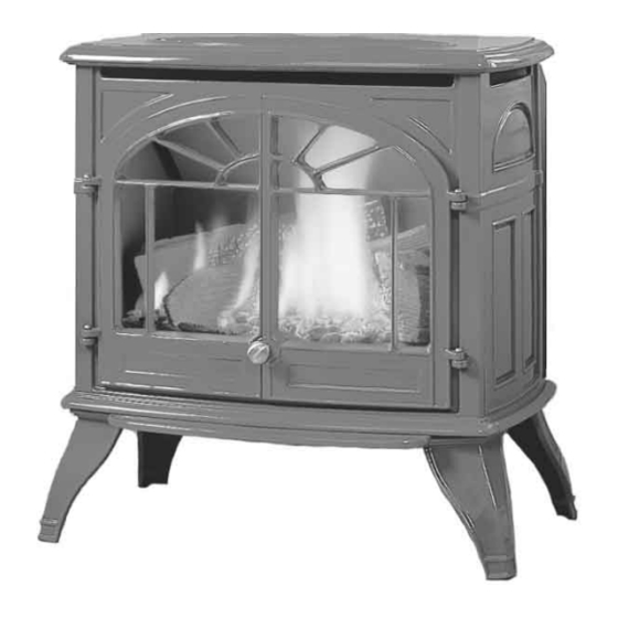
Westport
B Y : S H E R W O O D I N D U S T R I E S L T D
This appliance may be installed in an after-market
permanently located, manufactured (mobile)
home, where not prohibited by local codes.
This appliance is only for use with the type of gas
indicated on the rating plate. This appliance is
not convertible for use with other gases, unless a
certified kit is used.
50-1033
Advertisement
Table of Contents

Related Manuals for Enviro Westport C-10794


Summary of Contents for Enviro Westport C-10794
- Page 1 SHERWOOD INDUSTRIES IS AN ENVIRONMENTALLY RESPONSIBLE COMPANY. THIS MANUAL IS PRINTED ON RECYCLED PAPER. PLEASE KEEP THESE INSTRUCTIONS FOR FUTURE REFERENCE OWNER’S MANUAL WHAT TO DO IF YOU SMELL GAS • Open windows/extinguish any open flame. • Do not try to light any appliance. •...
-
Page 2: Safety Precautions
Safety Precautions FOR SAFE INSTALLATION AND OPERATION OF YOUR “ENVIRO” HEATER, PLEASE CAREFULLY READ THE FOLLOWING INFORMATION: • All ENVIRO gas-fired appliances must be installed in accordance with their instructions. Carefully read all the instructions in this manual first. Consult the building authority having jurisdiction to determine the need for a permit prior to commencing the installation. -
Page 3: Table Of Contents
Table of Contents Safety Precautions...2 Table of Contents...3 Codes And Approvals...4 Specifications...5 Dimensions...5 Clearances to Combustibles...5 Operating Instructions...6 Pilot Lighting Instructions...6 Pilot Light...7 Air Shutter...7 Maintenance And Service...8 Routine Maintenance...8 Cleaning The Glass...8 Cleaning The Firebox...8 Change Battery in Ignition Module...8 Replacing the Glass...9 Opening The Door...9 Fuel Conversion...10... -
Page 4: Codes And Approvals
After the unit has gone through the first burn, turn the unit off including the pilot, let the unit get cold then remove the glass door and clean it with a good gas fireplace glass cleaner, available at your local ENVIRO dealer. -
Page 5: Specifications
WARNING: Operation of this heater when not connected to a properly installed and maintained venting system can result in carbon monoxide (CO) poisoning and possible death. IMENSIONS 27" (68.6cm) LEARANCES TO OMBUSTIBLES A. Sidewall to unit 11 inches (27.9 cm) B. -
Page 6: Operating Instructions
Operating Instructions For Your Safety, Read Safety Precautions And Lighting Instructions Before Operating WARNING: IF YOU DO NOT FOLLOW THESE INSTRUCTIONS EXACTLY A FIRE OR EXPLOSION MAY RESULT, CAUSING PROPERTY DAMAGE, PERSONAL INJURY OF LOSS OF LIFE. ILOT IGHTING NSTRUCTIONS Figure 3. -
Page 7: Pilot Light
Operating Instructions ILOT IGHT 1. Turn off the gas to the fireplace. If not recently done, remove the glass and let the unit air out for at least five (5) minutes to clear out any gas. Turn on gas to the heater. Leak test all joints with soapy water. -
Page 8: Maintenance And Service
Replace the logs and embers as in the L ET AND MBER NSTALLATION your nearest ENVIRO dealer. HANGE ATTERY IN GNITION If the unit does not spark when lighting, the battery in the electronic ignition could need replacing. -
Page 9: Replacing The Glass
Do not operate with the glass front removed, cracked or broken. Removal and replacement of the glass from the door must be done by a licensed or qualified service person. The glass must be purchased from an ENVIRO dealer. No substitute materials are allowed. -
Page 10: Fuel Conversion
Maintenance And Service TO BE INSTALLED BY A QUALIFIED SERVICE AGENCY ONLY ONVERSION Warning: This conversion kit shall be installed by a qualified service agency in accordance with the manufacturer’s instructions and all applicable codes and requirements of the authority having jurisdiction. If the information in these instructions is not followed exactly, a fire, explosion or production of carbon monoxide may result causing property damage, personal injury or loss of life. - Page 11 Maintenance And Service Step 8. Install the new pilot injector supplied with this conversion kit. Simply screw the new injector inside the pilot hood and reinstall the hood by placing the hood on the assembly, line up the key way, and snap into place. Step 9.
-
Page 12: Initial Installation
Initial Installation ERMINATION ESTRICTIONS Fixed Closed Openable Termination Cap Figure 10. Vent Termination Restrictions, refer to Table 2. Table 2: Vent termination clearances, refer to Figure 10. Letter Canadian Installation 12 in (30 cm) 12 in (30 cm) 12 in (30 cm)* 24 in (60 cm)* 18 in (45 cm)* 12 in (30 cm)*... -
Page 13: Vent Parts
Initial Installation QUALIFIED INSTALLERS ONLY ARTS Simpson Duravent (SD), Selkirk (SEL), and Security Chimneys (SC), must state if galvanized or black wanted, PART NUMBERS: Description 4DT-6 SV4L6 6” pipe length 4DT-9 9” pipe length 4DT-12 SV4L12 12” pipe length 4DT-24 SV4L24 24”... - Page 14 Initial Installation The ENVIRO WESTPORT has been designed with a built in restrictor plate. The restrictor is designed to enhance flame appearance when installing this unit with vertical chimneys as well as installations with longer horizontal vent applications. It does this by controlling the amount of air moving through the vent pipe.
-
Page 15: Planning Your Installation
Initial Installation QUALIFIED INSTALLERS ONLY LANNING NSTALLATION When planning your installation, it will be necessary to select the proper length of vent pipe for your particular requirements. It is important to note when passing through a wall, the maximum allowable wall thickness is 10 inches (25.4 cm), 11⁄2 inches (3.8 cm) clearance to combustibles must be maintained. -
Page 16: Horizontal Installation
Initial Installation ORIZONTAL NSTALLATION STEP 1. Set the appliance in the desired location. Check to determine if wall studs or roof rafters are in the way when the venting system is attached. If this is the case, you may want to adjust the location of the appliance. - Page 17 Initial Installation QUALIFIED INSTALLERS ONLY every 36 inches (915 mm). Wall straps are available for this purpose, also when running horizontal pipe minimum clearances to combustibles must be maintained; 2 inches (51 mm) at top, 11⁄2 inches (38 mm) at sides, 11⁄2 inches (38 mm) at bottom. STEP 3.
-
Page 18: Corner Installations
Initial Installation NOTES: (1) The four (4) wood screws provided should be replaced with the appropriate fasteners for stucco, brick, concrete, or other types of siding. (2) For buildings with vinyl siding, a vinyl siding standoff, should be installed between the vent cap and the exterior wall (see Figure 19). -
Page 19: Vertical Installation
Initial Installation QUALIFIED INSTALLERS ONLY ERTICAL NSTALLATION STEP 1. Check the instructions for required clearances (air spaces) to combustibles when passing through ceilings, walls, roofs, enclosures, attic rafters, or other nearby combustible surfaces. Do not pack air spaces with insulation. STEP 2. - Page 20 Initial Installation down to the roof level, as shown in Figure 24. Tighten the clamp around the pipe section. Use a level to make sure the pipe is truly vertical. With roofing nails, secure the support straps to the roof. Seal the nails holes heads with non-hardening mastic. Trim the excess length of the support straps that extend out beyond the edge of the flashing.
-
Page 21: Cathedral Ceiling Installation
Initial Installation QUALIFIED INSTALLERS ONLY plumber’s tape connected to wall strap Wall strap 45° elbows (x2) Figure 26: Use of Wall Straps. manufactures installation instructions for the minimum allowable clearance between the outside of the vent pipe, and the combustible surfaces of the enclosure. Do not fill any required air spaces with insulation. -
Page 22: Freestanding Direct Vent Kit With Coupler
Initial Installation Figure 28: Cathedral Ceiling Support Box Leveling. REESTANDING IRECT KIT COMPONENTS: Quantity Description Horizontal direct vent termination cap Flue collar adapters (only one used) T-20 Torx screws Wall thimble Inside finish trim collar 11⁄2” wood screws 5’ (190 cm) length of Ø4” (10 cm) double walled flex pipe Please ensure that all components are supplied with this kit. - Page 23 Initial Installation QUALIFIED INSTALLERS ONLY 3. Set the appliance in the desired location. Temporarily place a 24” (61 cm) section with the non- crimped end on the unit 4. Install the 90° elbow onto the vertical pipe on the stove pointing in the direction that the vent will exit the structure.
- Page 24 Initial Installation 20. Align all straight sections of pipe, slipping all joints together and installing with three (3) sheet metal screws evenly spaced. 21. Install the brass decorative rings around each joint making sure this decorative ring covers the sheet metal screws that secure each section of pipe together and secure to vent pipe in the slotted tab on the backside of the pipe so that the fastener would not be seen.
-
Page 25: Venting Into A Class 'A' Chimney
Initial Installation QUALIFIED INSTALLERS ONLY ‘A’ C ENTING INTO A LASS HIMNEY This model is also certified and tested to vent into CLASS ‘A’ wood stove chimneys. Place the freestanding direct vent appliance in the desired location. Use a conversion kit from Simpson Duravent (931, 932, or 933), or Security Chimney (SV4CCK1, SV4CCK2, or SV4CCK1). -
Page 26: Converting Top Vented Into Rear Vented
Initial Installation ONVERTING ENTED INTO This unit has been shipped as a 30,000 Btu/hr top-vented freestanding unit. This unit can be converted to a rear vented unit with a 36” (915 mm) snorkel for some installation applications.To convert this unit to a rear vented model you must remove the flue pipe adapter and turn to the rear vent position. -
Page 27: Installation Of Top Vented; Horizontal Termination
Initial Installation QUALIFIED INSTALLERS ONLY NSTALLATION OF ENTED This is the most common type of installation style. Set the unit in place. Install a minimum 24” (61 cm) vertical chimney. Install a 90° elbow, and mark the exterior wall where the vent would pass through. -
Page 28: Freestanding Drafthood Adaptor
Initial Installation REESTANDING RAFTHOOD This Drafthood Adaptor is a complete assembly and is ready to fit onto your Westport in a vertical vent application only. With the Drafthood Adaptor correctly installed and wired to the gas control valve. Your Direct Vent Fireplace can be vented like a B-Vent Fireplace. INSTALLATION: WARNING: This Freestanding Drafthood Adaptor must be fitted by a qualified service technician. -
Page 29: General Venting Information
Initial Installation GENERAL VENTING INFORMATION: Canadian Installations The venting system must be installed in accordance with the current CSA B149 installation code and/or local codes having jurisdiction. U.S.A. Installations The venting system must be installed in accordance with the current National Fuel Gas Code, ANSI Z223.1, and/or local codes having jurisdiction. -
Page 30: Automatic Safety Shut Down
Initial Installation 4. After a minimum of 10 minutes operation, test the chimney draft with a smoke match at the top row of the pattern to confirm that there is adequate draft or ‘pull’ at the openings around the body of the Drafthood Adaptor, as shown in Figure 42. -
Page 31: Gas Line Connection And Testing
Initial Installation QUALIFIED INSTALLERS ONLY ONNECTION AND ESTING WARNING: Only persons licensed to work with gas piping may make the necessary gas connections to this appliance. GAS LINE CONNECTION This stove is equipped with a certified flexible pipe • located on the right side of the unit terminating in a 3⁄8” male NPT fitting. -
Page 32: Electrical Requirements For Gas Valve And Optional Blower
LECTRICAL EQUIREMENTS The ENVIRO WESTPORT will operate without electrical power. This model has a millivolt gas control, which uses the pilot flame to generate enough electricity to operate the main burners. The appliance when equipped with an optional blower must be electrically connected and grounded in accordance with local codes or in the absence of local codes, with the current CSA C22.1 CANADIAN ELECTRICAL CODE... -
Page 33: Secondary Installation
If over time, through cleaning and servicing, these embers require replacement, contact the nearest ENVIRO dealer for replacement embers. 2. Ensure the temperature sensor will touch the unit when mounted. If it does not touch, adjust the sensor so it does. - Page 34 Secondary Installation 1. Carefully remove logs from box. Check to ensure there is no damage. It is very important to install all logs in their proper position to insure safe, optimum operating conditions. 2. Place the log set into the firebox.
- Page 35 Figure 53: Log Placement with Rock Wool. cold then remove the glass door and clean it with a good gas fireplace glass cleaner, available at your local ENVIRO dealer. See M on how to remove AINTENANCE ERVICE door to clean glass.
-
Page 36: Installation Of Panel Set
Secondary Installation NSTALLATION OF ANEL Do not install when the unit is hot. The brick panel set is fragile. Handle panels with care and avoid knocking them on the placement pins or any other object. Figure 56: Brick panel bracket, slots shown. Figure 57: Top brick panel in place, screws shown. -
Page 37: Trouble Shooting
Trouble Shooting Problem Possible Cause Spark will not light Defective piezo ignitor. the pilot after repeatedly pressing the spark ignitor Broken spark electrode. • Check for broken ceramic insulation. Low battery or bad electronic module. Misaligned spark electrode. Pilot will not remain Problem with thermocouple circuit. -
Page 38: Parts List - Cast
Parts List - Cast Reference Number Part Description Top Vent Insert Piece - Painted Top Vent Insert Piece - Antique White Top Vent Insert Piece - Diamond Black Top Vent Insert Piece - Inferno Red Top Vent Insert Piece - Pearl Grey Top Vent Insert Piece - Wedgewood Blue Top Vent Insert Piece - Westport Green Top Vent Insert Piece - Antique Chestnut... - Page 39 Parts List - Cast Reference Number Part Description Cast Leg (Each) - Painted Cast Leg (Each) - Antique White Cast Leg (Each) - Diamond Black Cast Leg (Each) - Inferno Red Cast Leg (Each) - Pearl Grey Cast Leg (Each) - Wedgewood Blue Cast Leg (Each) - Westport Green Cast Leg (Each) - Antique Chestnut Ash Shelf - Painted...
-
Page 40: Parts Diagram - Cast
Parts Diagram - Cast � � WESTPORT - Castings � January 2005 � � � � �... -
Page 41: Parts List - Components
Parts List - Components Reference Part Description Number 120° Ceramic Fan Temperature Sensor S.I.T. Nova Valve NG (50% Turn Down) S.I.T. Nova Valve LP (50% Turn Down) Thermocouple Spark Electrode with Ignitor Cable Thermopile Pilot Orifice NG Threaded Pilot Orifice LP Threaded Pilot Gasket S.I.T. - Page 42 Parts List - Components Reference Number Part Description Rating Plate (Label) Gas Valve Cover Flue Connection Inner Door Handles (2 per set) Venturi Adjustment Rod Firebox Burner 45° Elbow & Gasket Fan Kit 180 C.F.M. Door Knob - Brushed Nickel Electronic Ignition Module Switch Blank Orifice #73 - All Gas Models Wiring Harness...
-
Page 43: Parts Diagram - Components
Parts Diagram - Components �� �� �� �� �� �� �� WESTPORT - Components January 2005 �� �� �� �� �� �� �� �� �� �� �� �� �� �... -
Page 44: Warranty
Warranty Sherwood Industries Ltd. offers a Limited Lifetime Warranty on this gas product. This limited lifetime warranty covers the appliance for a period of seven years from the date of installation. This warranty applies only to the original owner in the original location Covered under the lifetime warranty are, Surround Panels and Chassis and Heat Exchanger. -
Page 45: Installation Data Sheet
Installation Data Sheet The following information must be recorded by the installer for warranty purposes and future reference. NAME OF OWNER: _________________________________________ ADDRESS: _________________________________________ _________________________________________ _________________________________________ PHONE:___________________________________ MODEL:___________________________________ SERIAL NUMBER:___________________________ DATE OF PURCHASE: _____________ DATE OF INSTALLATION:___________ � � NATURAL GAS (NAT) INLET GAS PRESSURE:_________in wc MAIN BURNER ORIFICE:__________# DMS PILOT ORIFICE #_________OR________in diam.
Need help?
Do you have a question about the Westport C-10794 and is the answer not in the manual?
Questions and answers