
Related Manuals for Smart Technologies Parts Kit for SMART Board 560


Summary of Contents for Smart Technologies Parts Kit for SMART Board 560
- Page 1 Configuration and User’s Guide Parts Kit for SMART Board™ 560 and 580 Interactive Whiteboards and UF55 Projectors...
- Page 2 © 2009 SMART Technologies ULC. All rights reserved. No part of this publication may be reproduced, transmitted, transcribed, stored in a retrieval system or translated into any language in any form by any means without the prior written consent of SMART Technologies ULC. Information in this manual is subject to change without notice and does not represent a commitment on the part of SMART.
-
Page 3: Important Information
Important Information Read This Section First NOTE: If you own a SMART product other than a parts kit for SMART Board 560 and 580 interactive whiteboards and UF55 projectors, refer to the installation guide that came with your product for relevant warnings and maintenance instructions. -
Page 4: Safety Warnings
• The lamp used in the UF55 projector contains mercury. Recycle or dispose of it as hazardous waste, in accordance with local regulations. • Use only replacement lamps approved by SMART Technologies. Contact your authorized SMART reseller for replacement parts. - Page 5 • Cleaning a boom-mounted projector may result in a fall or injury. • Don’t add extra weight or apply pressure to the UF55 projector boom, the wall-mounted interactive whiteboard or its pen tray. SMART Technologies designed the brackets to support only the weight of the components during normal use.
- Page 6 • Never operate your projector immediately after moving it from a cold location to a warm CAUTION location. When your projector is exposed to such a change in temperature, moisture may condense on the lens and on crucial internal parts. Allow your projector to reach room temperature before operation to prevent possible damage to your projector.
-
Page 7: Other Precautions
• If the interactive whiteboard system requires replacement parts, make sure that the service technician uses replacement parts specified by SMART Technologies, or parts with the same characteristics as the original. 99-00964-20 A0 Important Information... - Page 8 Important Information 99-00964-20 A0...
-
Page 9: Table Of Contents
Table of Contents Important Information Read This Section First........................... i Safety Warnings ............................. ii Other Precautions ............................v Table of Contents About Your UF55 Projector Parts Kit UF55 Projector System Features........................2 Standard Accessories ............................ 3 Installing Your UF55 Projector Parts Kit Environmental Requirements......................... -
Page 10: Table Of Contents
Hardware Environmental Compliance Waste Electrical and Electronic Equipment Regulations (WEEE Directive)..........59 Restriction of Certain Chemicals (REACH Directive) ...................59 Restriction of Certain Hazardous Substances (RoHS) Directives..............59 Batteries ...............................59 Packaging ..............................59 China’s Electronic Information Products Regulations ..................60 U.S. Consumer Product Safety Improvement Act..................60 Customer Support Online Information and Support ........................61 Training ................................61... -
Page 11: About Your Uf55 Projector Parts Kit
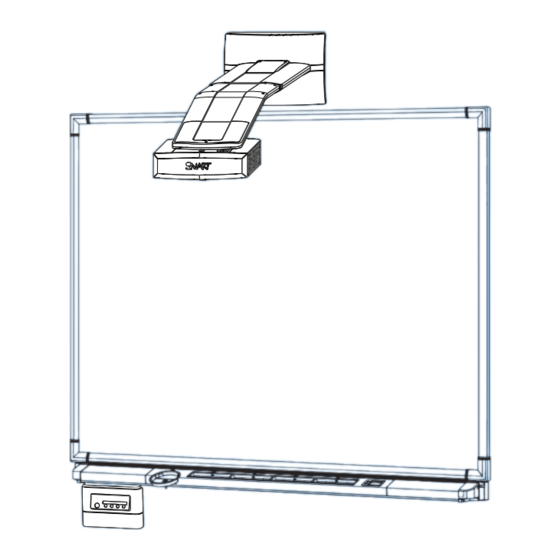
About Your UF55 Projector Parts Kit Your UF55 projector parts kit enables you to combine the SMART UF55 wall-mounted short-throw projector with your SMART Board 580 or 560 interactive whiteboard to create a complete interactive whiteboard system. The following topics describe the features of the components and accessories included in your parts kit. •... -
Page 12: Uf55 Projector System Features
UF55 Projector System Features The UF55 projector system includes a short-throw projector for use with SMART Board interactive whiteboards, an extended control panel (ECP) and a sturdy support system for classroom environments. The projector system has the following features: • A wall-mounted, high-offset SBP-10X (for XGA or UF55) projector engine that uses DLP®... -
Page 13: Standard Accessories
Standard Accessories SMART provides the following accessories with your UF55 projector parts kit. If you need to purchase replacements, contact your authorized SMART reseller. ECP and Cable The interactive whiteboard system’s ECP features connectors for three inputs and control for four inputs, including the direct HD-DB15 RGB connection to the projector. - Page 14 About Your UF55 Projector Parts Kit 99-00964-20 A0...
-
Page 15: Installing Your Uf55 Projector Parts Kit
Installing Your UF55 Projector Parts Kit Use the instructions from the UF55 projector boxes to install your parts kit, including the IMPORTANT projector and ECP mounting template. Don’t use the instructions in your SMART Board interactive whiteboard product box. The following sections include additional information, optional procedures and tips to consider when you install your SMART Board interactive whiteboard system with the UF55 projector parts kit. -
Page 16: Environmental Requirements
Environmental Requirements Before installing your UF55 projector parts kit, review the following environmental requirements. • Never operate your projector immediately after moving it from a cold location to a warm CAUTION location. When your projector is exposed to such a change in temperature, moisture might condense on the lens and on crucial internal parts. -
Page 17: Choosing A Location For Your Smart Board Interactive Whiteboard System
Choosing a Location for Your SMART Board Interactive Whiteboard System Choose a location for your SMART Board interactive whiteboard system that’s far from bright light sources and direct sunlight such as a window or overhead lighting. Bright light sources can cause distracting shadows on the interactive whiteboard and reduce the contrast of the projected image. -
Page 18: Adjusting The Image Alignment
Adjusting the Image Alignment After you install the UF55 projector with your SMART Board 500 series interactive whiteboard, you must adjust the image alignment. Diagnosing Alignment Errors Keystone errors occur when the projected image isn’t perpendicular to the screen. From the projector, the image path is From the projector, the image path is shorter along the top. - Page 19 Adjust the interactive whiteboard side to side to center the image (from the projector), as illustrated in the installation document, the Parts Kit for SMART Board 560 and 580 Interactive Whiteboards and UF55 Projectors (document 134836). This eliminates many keystone errors. If your installation environment prevents you from moving the interactive whiteboard, you can adjust the projector boom for optimal image alignment.
- Page 20 Tilt the projector left or right, up or down, or move it from side to side, until the top edge of the projector image is parallel with the top edge of the interactive whiteboard. Installing Your UF55 Projector Parts Kit 99-00964-20 A0...
- Page 21 Adjust the vertical keystone alignment for the projected image. If the bottom edge of the projected image is smaller than the top edge of the projected image, and the sides of the projected image slope inward toward the bottom of the projected image, tilt the projector down or raise the projector’s mounting boom to lower the image.
- Page 22 Adjust the projected image’s horizontal alignment by turning the projector left or right, until the top and bottom edges of the projected image are horizonally parallel. NOTE: Don’t pay attention to the position of the left and right edges in relation to the interactive whiteboard during this step.
- Page 23 Adjust the physical size of the projected image to fit the interactive whiteboard. If you haven’t already done so, loosen the large wingnut on the top of the ball joint to allow the projector to move backward and forward in the slot. Move the projector backward or forward on the boom to make the image larger or smaller.
-
Page 24: Focusing The Image
Focusing the Image NOTE: Ensure that you remove the plastic lens cover from the projector. To focus the projected image, use the Focus Ring, located on the bottom of the UF55 projector (when the projector is attached to the boom). To focus and adjust the image Rotate the Focus Ring lever right or left until the image is clear. -
Page 25: Connecting Your Interactive Whiteboard System
Connecting Your Interactive Whiteboard System When you connect a computer with SMART Notebook software to your interactive whiteboard system, you can display and interact with Ink Aware programs on your SMART Board interactive whiteboard. You can connect the video output of a hardware device, such as a DVD/Blu-ray player or VCR, to the interactive whiteboard system’s ECP to display this video signal on your system. -
Page 26: Connecting The Cables To The Uf55 Projector
Connecting the Cables to the UF55 Projector Refer to the following diagrams as you connect the cables to the projector. Routing the Cables When connecting cables from the UF55 projector to the 560 or 580 interactive whiteboard, make sure all cables pass along the top of the mounting bracket and down the left or right side of the interactive whiteboard. - Page 27 Pass the ECP cable through the boom. The upper portion of the ECP cable is too thick to fit inside the cable slot. Put all the cables on the thinner portion of the ECP in the cable slot to the left instead. Set up the ECP cabling by connecting each section separately.
- Page 28 Connect the ECP DB9 control cable from the ECP to the DB9 socket in section D. Connect the VESA RGB (VGA) connector and the DB25 connector from the harness cable to the ECP. DB25 VGA Connector Connector Connecting Your Interactive Whiteboard System 99-00964-20 A0...
- Page 29 Pass the Audio, VGA and network cables (not supplied) through the boom, and connect them to your projector. Connect the Audio 1 and Computer 1 VGA from your external computer (section E). Connect the RJ45 network cable from your external LAN receptacle (section F). NOTE: These cables are for optional equipment.
- Page 30 Connecting Audio/Visual Outputs from Your Guest Computer to Your Interactive Whiteboard System’s ECP Input Use the VGA connector on the ECP to connect your guest computer’s video output. If you do IMPORTANT not have a guest computer, you can use the VGA connector on the ECP to connect your host computer’s video output.
- Page 31 Connecting Peripheral Visual or Audio-Visual Devices To connect a DVD/Blu-ray player, VCR, document camera, digital camera or other visual or audio-visual peripheral device to the SMART Board interactive whiteboard system, you must connect the device’s video and audio outputs to the ECP. You can have up to three peripheral devices and a host computer connected at one time.
- Page 32 Connecting Your Interactive Whiteboard System 99-00964-20 A0...
-
Page 33: Using Your Interactive Whiteboard System
Using Your Interactive Whiteboard System This chapter describes the basic operation of your interactive whiteboard system, how to retrieve system information and how to access the projector’s image adjustment options. • Turning the System On and Off and Selecting an Input (this page) •... -
Page 34: After Completing The Installation
After Completing the Installation When you connect your interactive whiteboard system to a computer with SMART Board or SMART Notebook software installed, the computer interprets your touch on the interactive screen as left mouse clicks and moves the mouse pointer to the corresponding point on the screen. You can also write over your desktop or any open application with digital ink, and then capture and save these notes to a Notebook file for future reference and distribution. - Page 35 Menu Options The menu heading at the top of all settings is SMART UF55 Settings. Menu Heading Settings Description Display Mode This option adjusts the display output to User, sRGB, Dark Classroom and Bright Classroom. Image Adjustment Brightness This option adjusts projector brightness from 0 to 100. Contrast This option adjusts projector contrast from 0 to 100.
- Page 36 Menu Heading Settings Description Mute, Disable Use these options to turn your settings On or Off. Volume Control Audio Control and Closed Captioning Closed This option adjusts the closed captioning language to CC1 or CC2. Captioning Language Auto Signal Detect Select On to scan until the first input signal is found, or select Off to keep signal detection in one input connector.
- Page 37 Menu Heading Settings Description IP Address This option displays your IP address in x.x.x.x format. Network Settings Subnet Mask This option displays your subnet mask number in x.x.x.x format. Gateway This option displays your default gateway of the network to the projector in x.x.x.x format.
- Page 38 Using Your Interactive Whiteboard System 99-00964-20 A0...
-
Page 39: Maintaining Your Uf55 Projector
Maintaining Your UF55 Projector This chapter includes methods for properly cleaning and for preventing damage to your SMART Board interactive whiteboard system. • Cleaning Your UF55 Projector (this page) • Transporting Your Projector (page 30) Cleaning Your UF55 Projecto WARNING Cleaning a boom-mounted projector may result in a fall and injury. -
Page 40: Transporting Your Projector
Transporting Your Projector Save your original UF55 projector parts kit packaging so that it’s available if you need to transport your system. When required, repack it with as much of the original packaging as possible. This packaging was designed with optimal shock and vibration protection. If your original packaging is no longer available, you can purchase replacement packaging from your authorized SMART reseller. -
Page 41: Troubleshooting Your Interactive Whiteboard System
Troubleshooting Your Interactive Whiteboard System This chapter provides basic troubleshooting information for your SMART Board interactive whiteboard system. For issues not mentioned in this section, please contact your authorized SMART reseller or consult the SMART Support website. Topics include the following: •... -
Page 42: Errors
Power LED Temperature LED Message (Green/Amber) (Red) Idle mode Solid amber Powering Flashing green On (Lamp On) Solid green Cooling Flashing amber Error (Temperature Exceeded) Flashing red Error (Fan Failure) Solid red Error (Color Wheel Failure) Solid red Error (Lamp Failure) Solid amber Flashing red Errors... - Page 43 Fan Failure If the Fan Failure indicator message appears and your projector turns off during use, one of the following issues is occurring: • One of the fans has failed. • Your projector is overheating internally. To resolve your Fan Failure error Disconnect the power cable and then contact your authorized SMART reseller.
- Page 44 Ready Light Isn’t Lit If your Ready light isn’t lit, one of the following issues is occurring: • There is a power outage or a power surge. • A circuit breaker or a safety switch was tripped. • Your projector isn’t connected to a power source. •...
-
Page 45: Appendix A: Remotely Managing Your Interactive Whiteboard System
Appendix A: Remotely Managing Your Interactive Whiteboard System This appendix provides detailed instructions on how to set up your computer or your room control system to manage your SMART Board interactive whiteboard system settings. • Programming Commands for Your SMART Board Interactive Whiteboard System Settings (this page) –... - Page 46 Pin Configuration on the ECP RS-232 Connector The following table provides the pin configuration on the ECP. This configuration follows a three-wire connection, so that a straight-through male to female RS-232 serial cable connects to the ECP serial interface in the following arrangement.
- Page 47 To configure your serial interface CAUTION Do not connect your serial cable directly to the projector’s RS-232 serial interface. The ECP’s RS-232 serial interface is the only recommended connection point. Turn on your computer, and then start your serial communications program or terminal emulation program. Connect your computer to the ECP’s serial connector using a DB9 cable.
-
Page 48: Command Inventory
Command Inventory The UF55 projector responds to the commands in the tables on the following pages. NOTES • Commands aren’t case sensitive. • Type commands exactly as they appear in the left column of the tables. • Press ENTER after typing each command. •... - Page 49 To control the sequence programmatically Send Command: Wait for Command Prompt Send Command: get powerstate Wait for Command Prompt Response: powerstate=on Send Command: set input=vga1 Wait for Command Prompt 99-00964-20 A0 Appendix A: Remotely Managing Your Interactive Whiteboard System...
- Page 50 Powerstate Control Allows the projector to turn on or off and switch between other related controls. Command Response Powered Off powerstate=[powerstate] powerstate=[powerstate] off [off option] powerstate=[powerstate] get powerstate NOTE: You must send the off command twice. The first command displays an on-screen message, and the second command shuts off the system.
- Page 51 Source Selection Allows you to switch between input sources. Command Response Powered Off input=[current] set input [target] input=[current] get input [current] Field Possible Values Description target input =VGA1 Allows you to select which application you would like to switch to =VGA2 =Composite =S-Video...
- Page 52 Video Control Allows you to switch between Video output controls. Command Response Powered Off brightness=[current] set brightness [target] brightness=[current] get brightness set contrast [target] contrast=[current] contrast=[current] get contrast Field Possible Values Description target brightness +val If you specify a + or - before the value, it adds or subtracts it from the current -val value.
- Page 53 Audio Control Allows you to switch between audio output controls. This value range should match the range displayed on the on-screen display. Command Response Powered Off volume=[current] set volume [target] volume=[current] get volume Field Possible Values Description target volume +val If you specify a + or - before the value, it adds or subtracts it from the current -val...
- Page 54 Field Possible Values Description current netstatus connected Displays the current state of the network interface disconnected current dhcp Displays whether the DHCP networking is enabled or disabled target dhcp Displays whether the DHCP networking is enabled or disabled =off current ipaddr x.x.x.x Displays the current IP address target ipaddr...
- Page 55 System Information Allows you to switch system information. Command Response Powered off projectorid=[current] get projectorid serialnum=[current] get serialnum lamphrs=[current] get lamphrs syshrs=[current] get syshrs fwverddp=[current] get fwverddp fwvernet=[current] get fwvernet fwvermpu=[current] get fwvermpu fwver=[current] get fwver bootver=[current] get bootver Field Possible Values Description current projectorid...
- Page 56 Appendix A: Remotely Managing Your Interactive Whiteboard System 99-00964-20 A0...
-
Page 57: Appendix B: Replacing Your Uf55 Projector Lamp
Appendix B: Replacing Your UF55 Projector Lamp This appendix has detailed instructions on how to replace your projector lamp. Topics include the following: • Replacing the Projector Lamp (this page) – Removing the Projector from the Boom (page 49) – Replacing the Projector Lamp Module (page 52) –... - Page 58 • The lamp used in the UF55 projector contains mercury. Recycle or dispose of it as hazardous waste, in accordance with local regulations. • Use only replacement lamps approved by SMART Technologies. Contact your authorized SMART reseller for replacement parts.
- Page 59 Removing the Projector from the Boom Before you can replace the projector lamp, you must remove the projector from the boom. WARNING Two people are required to remove the projector. To remove the projector from the boom Wait for the projector to cool by allowing the fan to completely shut down.
- Page 60 While firmly holding the projector with your hand, and without putting pressure or weight on the projector boom, remove the one screw holding the cover in place. Put the screw in a safe place. Remove the cover on the top of the boom. Appendix B: Replacing Your UF55 Projector Lamp 99-00964-20 A0...
- Page 61 If you use a projector padlock, make sure that you remove it from the locking loop. If you need access to your projector locking screw, loosen the wingnut, slide the projector all the way back away from the interactive whiteboard’s screen, and then tighten the wingnut.
- Page 62 Replacing the Projector Lamp Module After you remove the lamp from the projector, follow these instructions to replace the lamp. To remove the old lamp Turn off the projector by pressing the power button located on the remote control. Make sure that the fan is completely off and then disconnect the power cable.
- Page 63 Pull up on the handle of the old lamp. Don’t touch any part of the lamp except the housing. Remove the old lamp. Recycle or dispose of the old lamp according to your local waste authority. Remove the new lamp from all of its packaging.
- Page 64 Put the outer lamp cover back into its original position. Re-attaching the Projector WARNING Two people are required to mount the projector. To re-attach the projector to the boom Align the hooks on the boom with the slots on the projector, and then slide the projector into place.
- Page 65 Retrieve the projector plate screw that you removed when you took the projector off the boom. Secure the projector to the plate with the screw. Re-attach your projector padlock (optional). Connect all cables to the projector and then attach the cable cover. Connect the power cable to the wall power outlet.
- Page 66 To re-adjust your image, see pages 9 to 13. Attach the cover on the top of the boom. Tighten the screw until it is secure, without putting pressure or weight on the projector boom. Appendix B: Replacing Your UF55 Projector Lamp 99-00964-20 A0...
- Page 67 Resetting the Lamp Timer After you replace the lamp, reset the lamp timer. To reset the lamp timer Press the power button on the ECP or the remote control to start the system. The ECP’s power light turns solid green when the system starts. To confirm that the lamp timer has been reset, access the service menu by pressing DOWN , UP , LEFT...
- Page 68 Appendix B: Replacing Your UF55 Projector Lamp 99-00964-20 A0...
-
Page 69: Hardware Environmental Compliance
Hardware Environmental Compliance SMART Technologies supports global efforts to ensure that electronic equipment is manufactured, sold and disposed of in a safe and environmentally friendly manner. Waste Electrical and Electronic Equipment Regulations (WEEE Directive) Waste Electrical and Electronic Equipment regulations apply to all electrical and electronic equipment sold within the European Union. -
Page 70: China's Electronic Information Products Regulations
China’s Electronic Information Products Regulations China regulates products that are classified as EIP (Electronic Information Products). SMART Technologies products fall under this classification and meet the requirements for China’s EIP regulations. U.S. Consumer Product Safety Improvement Act The United States has enacted the Consumer Product Safety Improvement Act which limits the lead (Pb) content in products. -
Page 71: Customer Support
Shipping and Repair Status Contact SMART’s Return of Merchandise Authorization (RMA) group, Option 5, +1.866.518.6791, for shipping damage, missing part and repair status issues. General Inquiries Address: SMART Technologies 3636 Research Road NW Calgary, AB T2L 1Y1 CANADA Switchboard: +1.403.245.0333 or Toll Free 1.888.42.SMART (U.S./Canada) -
Page 72: Warranty
Warranty Product warranty is governed by the terms and conditions of SMART’s “Limited Equipment Warranty” that shipped with the SMART product at the time of purchase. Customer Support 99-00964-20 A0... -
Page 73: Index
Index Adjusting Environmental requirements Default settings Cautions, 6 Auto input search, 26 Dust and scratching, 6 Keystone, 26 Electrostatic discharge, 6 Image adjustment options, 27 Humidity, 6 Brightness, 25 Water and fluid resistance, 6 Contrast, 25 Wave interference, 7 Keystone alignment, 8 Extended control panel (ECP) Position adjustment options About, 3... - Page 74 Using the remote control, 24 Using your UF55 projector, 24 REACH directive, 59 Registration, 61 Remote control menu, 27 Warning lights, 31 Removing the projector plate assembly, 47, 49 Warranty, 62 Replacing the projector lamp, 47 Wave interference, 7 Resetting the lamp timer, 56 WEEE directive, 59 RoHS directives, 59 SMART Board interactive whiteboard system...
- Page 76 SMART Technologies 3636 Research Road NW Calgary, AB T2L 1Y1 CANADA www.smarttech.com/support www.smarttech.com/contactsupport Support +1.403.228.5940 Toll Free 1.866.518.6791 (U.S./Canada) 99-00964-20 REV A0...
Need help?
Do you have a question about the Parts Kit for SMART Board 560 and is the answer not in the manual?
Questions and answers