Table of Contents
Advertisement
Quick Links
Manual
This is a User's Manual for the EUROCOM 3100C DeskNote
ENJOY THE PURCHASE OF YOUR NEW EUROCOM 3100 DeskNote .
Notice
The company reserves the right to make any updates, revisions or changes to the
information contained herein as and when deemed necessary. The company is under
no obligation to notify any purchaser or end-user of such actions in advance or
afterwards.
1999
Trademarks
DeskNote
is a registered trademark of EUROCOM Corporation.
IBM PC, OS/2, PS/2, EGA, and VGA are registered trademarks of International
Business Machines Corporation.
Intel, Pentium are trademarks of Intel Corporation.
MS-DOS, Microsoft Windows, Windows NT and Microsoft Mouse are registered
trademarks of Microsoft Corporation.
Sound Blaster Pro is a trademark of Creative Labs, Inc.
SystemSoft is a registered trademark of SystemSoft Corp.
Other brand and product names are trademarks of their respective companies.
Advertisement
Table of Contents

Related Manuals for EUROCOM 3100-B Mobile Cinema


Summary of Contents for EUROCOM 3100-B Mobile Cinema
- Page 1 Manual This is a User’s Manual for the EUROCOM 3100C DeskNote ENJOY THE PURCHASE OF YOUR NEW EUROCOM 3100 DeskNote . Notice The company reserves the right to make any updates, revisions or changes to the information contained herein as and when deemed necessary. The company is under no obligation to notify any purchaser or end-user of such actions in advance or afterwards.
-
Page 2: Table Of Contents
Table of Contents CHAPTER 1 CHAPTER 1 CHAPTER 1 CHAPTER 1: : : : GETTING STARTED ----------------------------------------------1-1 ----------------------------------------------------------1-2 NPACKING THE --------------------------------------------------------1-3 EATURES OF THE Opening the LCD Cover -----------------------------------------------------------1-3 Power button --------------------------------------------------------------------------- 1-4 System Status LED Indicators----------------------------------------------------- 1-5 Top-Front View ----------------------------------------------------------------------1-6 LCD Panel ------------------------------------------------------------------------------ 1-6 Keyboard-------------------------------------------------------------------------------- 1-7 Stereo Speakers ---------------------------------------------------------------------- 1-7... - Page 3 Battery Pack--------------------------------------------------------------------------1-16 Removing ------------------------------------------------------------------------------- 1-16 Inserting --------------------------------------------------------------------------------- 1-16 Recharging by AC Power ----------------------------------------------------------- 1-20 Proper Handling of the Battery Pack--------------------------------------------- 1-18 CHAPTER 2 CHAPTER 2 CHAPTER 2 CHAPTER 2: : : : OPERATION --------------------------------------------------------2-1 ---------------------------------------------------2-2 PGRADING ROCESSOR ODULE Replacing Processor Module ------------------------------------------------------2-2 Reinstalling the Heat Sink ---------------------------------------------------------2-3 DIP S ------------------------------------------------------------------2-4...
- Page 4 Resume from POS Mode ----------------------------------------------------------- 2-26 Suspend To Disk (STD) ------------------------------------------------------------- 2-27 Resume from STD Mode ----------------------------------------------------------- 2-27 ---------------------------------------------------2-28 TTACHING ERIPHERAL EVICES Attaching a Phone Line (option)--------------------------------------------------2-29 Attaching a PS/2 Keyboard or Mouse -------------------------------------------2-29 Attaching a Serial Mouse ----------------------------------------------------------2-30 Attaching a Parallel Printer--------------------------------------------------------2-31 Attaching an External Monitor (CRT) -------------------------------------------2-31 Attaching a Proprietary Port Replicator -----------------------------------------2-32 Attaching a TV Set------------------------------------------------------------------2-34...
- Page 5 CHAPTER 5 CHAPTER 5: : : : INSTALLING DRIVERS------------------------------------------1 CHAPTER 5 CHAPTER 5 ----------------------------------------------------------------------------2 REPARATION 95 (F )--------------------------------------2 NSTALLING INDOWS EFERENCE 98 (F ) --------------------------------------4 NSTALLING INDOWS OR REFERENCE 95 ----------------------------------------------5 NSTALLING RIVERS IN INDOWS Step 1: Run USB supplement path update file ---------------------------------5 Step 2: Installing TXPATCH Driver ---------------------------------------------5 Step 3: Installing VGA Driver ----------------------------------------------------5 Step 4: Installing Audio Driver --------------------------------------------------5...
- Page 6 Safety Notice A computer is a delicate device that requires careful handling. Negligence or mistaken use may cause serious damage. Before you learn to operate or use this computer, you need to understand the instruction regarding safety handling. The following mentions the incorrect handling that is seriously inhibited. To keep the computer from being damaged, please keep these precautions in your mind.
- Page 7 Do not place anything heavy on the Do not disassemble the computer computer. yourself. Do not touch power cord with a wet Do not use broken power cord. hand. Keep the computer away from any Do not throw the computer or accessories metal appliances.
- Page 8 The following mentions the actions that are important for your computer. To keep your computer in the most excellent condition, please follow the instruction as much as possible. If there is unusual odor, heat or smoke, Unplug the power cord when plug out the power cord immediately.
- Page 9 Maintain your computer regularly. Do not place heavy thing on the power cord. Affix tape to the contact plate while Take a rest after a long term of work. putting the battery into keeping box. The data is easy to lose in low power Please keep the computer away from status.
- Page 10 Conventions This manual uses the following conventions to describe, identify, and highlight terms and operating procedures. Text Conventions Text in boldface contains messages that are important for safe operation. Please read. Characters in boldface represent specific items or keys, e.g. CardBus, Fn key. File names are presented in bold capitals, e.g.
- Page 11 Ergonomics Developing good work habits are important if you need to work in front of the computer for long periods of time. Improper work habits can result in discomfort or serious injury from repetitive strain to your hands, wrists or other joints. The following are some tips to reduce the strain: Adjust the height of the chair and/or desk so that the keyboard is at or slightly below the level of your elbow.
- Page 12 Lighting Proper lighting and comfortable display viewing angle can reduce eye strain and muscle fatigue in your neck and shoulders. Position the display to avoid glare or reflections from overhead lighting or outside sources of light. Keep the display screen clean and set the brightness and contrast to levels that allow you to see the screen clearly.
-
Page 13: Chapter 1-Getting Started
Chapter 1—Getting Started 1-1 Chapter 1 Chapter 1 Chapter 1 Chapter 1 : Getting Starte d This chapter provides you with the brief introduction to the DeskNote. It will familiarize you to the computer’s features, components, operating environment and the power sources. Unpacking the DeskNote Features of the DeskNote Operating environment... - Page 14 Chapter 1—Getting Started 1-2 Unpacking EUROCOM 3100 DeskNote Carefully unpack the EUROCOM DeskNote and the included accessories (Figure 1- 1). If there is any discrepancy or problem, contact your dealer immediately. Be sure to save the packing materials in the event that the DeskNote needs to be shipped in the future.
-
Page 15: Opening The Lcd Cover
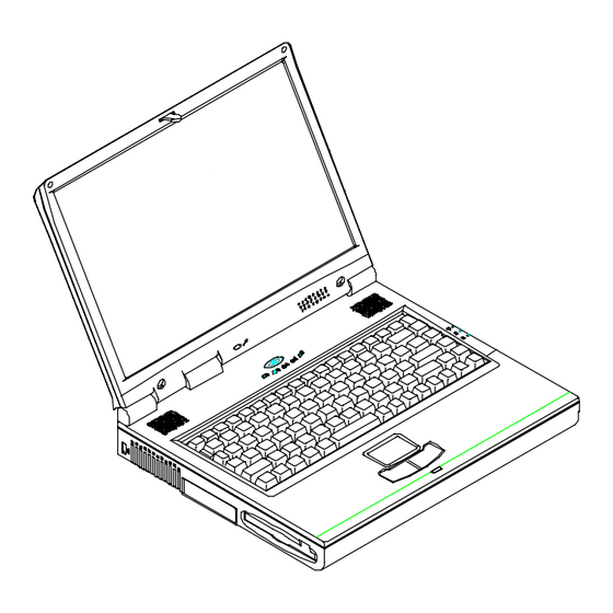
Chapter 1—Getting Started 1-3 Features of EUROCOM 3100 DeskNote Opening the LCD Cover Push the latch towards the right to open the top cover. (Figure 1-2) Lift the top cover to reveal the LCD panel and the keyboard. Adjust the LCD panel to a comfortable viewing angle. -
Page 16: Power Button
Chapter 1—Getting Started 1-4 System Status Indicators Power button Figure 1-4 Power button Use this button to turn the system on or off (Figure 1-4). After proper configuration under SCU, this button can be used as suspend/resume hot button (refer to Chapter 3: BIOS Utilities, Power Menu for more Figure 1-5 information). -
Page 17: System Status Led Indicators
Chapter 1—Getting Started 1-5 System Status LED Indicators The LED indicators show the system’s operation status. Icon Color Description Green Battery power is used with the system turning on. AC power is used with the system turning on. Blinking Red Battery power is critically low. -
Page 18: Top-Front View
Figure 1-5 LCD Panel The EUROCOM DeskNote is equipped with a LCD (Liquid Crystal Display) panel Depending upon the model you have purchased, the display screen can be a 13.3” or 14.1” XGA TFT color panel. The DeskNote’s LCD panel supports up to 1024×768×16M resolution. -
Page 19: Keyboard
Chapter 1—Getting Started 1-7 Keyboard The DeskNote uses an 88-key keyboard in which the numeric keypad is embedded. It supports Windows 95 by incorporating two Windows 95 special keys. The DeskNote keyboard design emulates a full-sized desktop one and supports various language versions. Please refer to chapter 2: Operation for more information on using keyboard. -
Page 20: Rear View
Chapter 1—Getting Started 1-8 Rear View Figure 1-6 PS/2 Type Ports The PS/2 Type Port uses 6-pin connector for connecting an external PS/2 type mouse or keyboard. Dual USB Ports The dual Universal Serial Bus (USB) ports simplify the expansion capability for peripheral devices. -
Page 21: Parallel Port
Chapter 1—Getting Started 1-9 Parallel Port The Parallel Port uses a 25-pin female connector for connecting a parallel printer or other parallel devices. This parallel port supports EPP (Enhanced Parallel Port) V1.7/V1.9 and ECP (Extended Capabilities Port) modes. AC-in Socket Plug the AC adapter into this socket for power supply. -
Page 22: Right-Side View
Chapter 1—Getting Started 1-10 Right-side View Figure 1-7 Battery Pack The DeskNote comes with a rechargeable battery pack that lets you operate the computer without an external power source. Removable 5.25” CD-ROM Drive The DeskNote comes standard with a 24-speed 5.25” CD-ROM drive. The removable CD-ROM drive module can be replaced with the optional drive units, such as a 12.7mm high DVD-ROM drive. -
Page 23: Left-Side View
Chapter 1—Getting Started 1-11 Left-side View Figure 1-8 Security Connector The Security Connector is used to protect your DeskNote from being stolen. Wrap the steel cable around your desk. Next, insert the locking device into this security connector. Ventilation The DeskNote provides ventilation to dissipate the system’s operating heat. Do not block or obstruct it during operation. -
Page 24: Bottom View
Chapter 1—Getting Started 1-12 Bottom View Figure 1-9 CD-ROM latch Push this latch to release the CD-ROM module from its bay. (Please refer to Chapter 2: Operation for more information on inserting or removing the CD-ROM.) Battery Pack latch Push this latch to release the Battery Pack from its bay. (Please refer to Chapter 1: Getting Started for more information on Inserting or removing the Battery Pack.) Floppy Disk Drive latch... -
Page 25: Hard Disk Drive Latch
Chapter 1—Getting Started 1-13 Hard Disk Drive latch Push this latch to release the Hard Disk Drive module from its bay. (Please refer to Chapter 2: Operation for more information on Inserting or removing the Hard Disk Drive.) -
Page 26: Operating Environment
Chapter 1—Getting Started 1-14 Operating Environment Proper care and operation of your EUROCOM DeskNote will prolong the use period. Make sure the computer is not: Exposed to excessively heat or direct sunlight. Subjected to shock or vibration. Exposed to strong magnetic fields. -
Page 27: Powering The System
Chapter 1—Getting Started 1-15 Powering the System You can use the AC power adapter or battery pack to power the computer system. AC Power Adapter Use only the power adapter that comes with your DeskNote Computer. Use the incorrect power adapter will cause damage to the DeskNote and its components. Plug the power adapter to the AC-in socket on the rear panel of the DeskNote. -
Page 28: Battery Pack
Chapter 1—Getting Started 1-16 Battery Pack Power for continuous portable operation of the DeskNote is provided by a battery pack. When the battery pack is fully charged, you can operate the computer for approximately two hours. However, the actual operating time will be determined by the application used and the configuration set. - Page 29 Chapter 1—Getting Started 1-17 Figure 1-12...
-
Page 30: Recharging By Ac Power
Chapter 1—Getting Started 1-18 Recharging by AC Power The system’s battery pack will recharge whenever the system is plugged into the AC power supply, regardless of whether the system is being operated or not. You may connect the AC power adapter to the DeskNote Computer at any time to begin recharging the system’s battery pack. -
Page 31: Chapter 2: : : : Operation
Chapter 2—Operation 2-1 Chapter 2 Chapter 2 Chapter 2 Chapter 2 : Operation The DeskNote has many advanced features to help you with your computing work. This chapter describes each of the DeskNote’s hardware features and shows you how to use them. Before you begin working with any internal components of the DeskNote, remove the battery and disconnect the AC power adapter. -
Page 32: Upgrading Processor Module
Chapter 2—Operation 2-2 Upgrading Processor Module Replacing Processor Module Remove all power sources (AC power and battery). Turn the DeskNote over. Remove the CPU cover. Remove the screws that fasten the heat sink mounted on the Processor Module. Carefully use the CPU removing tool to detach the Processor Module from the mainboard. -
Page 33: Reinstalling The Heat Sink
Figure 2 3 Chapter 2—Operation 2-3 Reinstalling the Heat Sink Make sure that the heat sink cable is properly placed. Figure 2-2 Figure 2-3... -
Page 34: Setting Dip Switch
Chapter 2—Operation 2-4 Setting DIP Switch Flash ROM BIOS update In order to keep up with the latest system BIOS, your DeskNote may be upgraded. Consult your dealer for further information. The DIP-Switch needs to be set in the On position when updating the existing system BIOS. The DIP-Switches should be reset to the Off position after BIOS updating is complete. -
Page 35: Accessing 8-Pole Dip Switch
Chapter 2—Operation 2-5 Accessing 8-Pole DIP Switch Access the 8-Pole DIP Switch to set the CPU Frequency. Turn the system power off. Press the two keyboard latches and Carefully lift the keyboard assembly out to expose the mainboard. Adjust the DIP Switch to set the configuration. Figure 2-4 Figure 2-4 Figure 2-5... -
Page 36: Expanding Memory
Chapter 2—Operation 2-6 Expanding Memory The system has three memory sockets for different RAM modules to expand the memory up to 256MB. These RAM modules are of a 144-pin SODIMM (Small Outline Dual In-line Memory Module) type. The DeskNote supports EDO, and SDRAM operation. -
Page 37: Accessing The Memory Sockets
Chapter 2—Operation 2-7 Accessing the Memory Sockets Turn the system power off. Press the two keyboard latches to elevate the keyboard from it normal position. Carefully lift the keyboard assembly out so that the mainboard is exposed. Locate the memory sockets (Figure 2-6/7). Note: "... -
Page 38: Installing Memory Module
Chapter 2—Operation 2-8 Installing Memory Module Follow the steps below to install the memory module: Turn the system power off. Press the two keyboard latches to elevate the keyboard from its normal position. Carefully lift the keyboard assembly out to expose the mainboard. -
Page 39: Removing Memory Module
Chapter 2—Operation 2-9 Removing Memory Module Turn the system power off. Press the two keyboard latches to elevate the keyboard from its normal position. Carefully lift the keyboard assembly out to expose the mainboard. Locate the memory sockets. Gently pull the two latches on both ends of the module outward. The module will pop up. -
Page 40: Using Hard Disk Drive
Chapter 2—Operation 2-10 Using Hard Disk Drive The DeskNote is equipped with a 2.5” IDE hard disk drive mounted in a removable case. Therefore, the hard disk drive can also be easily removed and replaced with another hard disk drive with a height of 17mm by using different case. The hard disk drive supports Programmed I/O (PIO) mode 4, Master mode and Ultra ATA (Ultra DMA-33) mode which can provide a high performance data transfer rate at speeds up to 33 MB/second. -
Page 41: Replacing Hard Disk Drive
Chapter 2—Operation 2-11 Replacing Hard Disk Drive Remove the two screws on each side of the case. (Figure 2-11) Gently disconnect the cable from the hard disk drive. Connect the replacement hard disk drive with the cable. Insert the replacement hard disk drive into the case. Fasten the screws of each side. -
Page 42: Using Floppy Disk Drive
Chapter 2—Operation 2-12 Using Floppy Disk Drive The DeskNote is equipped with a removable 1.44MB, 3.5” floppy disk drive module. It is usually designated as drive A by default and may be used as a boot device if properly set (please refer to Chapter 3, BIOS Utilities). You may replace the floppy disk drive module with the following options: a 2.5”... -
Page 43: Replacing Floppy Disk Drive
Chapter 2—Operation 2-13 Replacing Floppy Disk Drive Turn off the power. Turn the DeskNote over. Push the latch in the direction as indicated. (Figure 2-13-1) Draw the floppy disk drive module out of its bay. To assemble the floppy disk drive module into the bay. Insert the replacement module into the bay. -
Page 44: Write-Protecting Diskettes
Chapter 2—Operation 2-14 Write-Protecting Diskettes Diskettes can be write-protected to prevent files from being accidentally erased or destroyed. To write-protect a 3.5” floppy diskette, move the built-in write-protect tab to the write-protect position, (“up” so that you can see through the “hole” in the upper, right-hand corner of the diskette). -
Page 45: Using Cd-Rom
Chapter 2—Operation 2-15 Using CD-ROM The DeskNote is equipped with a removable CD-ROM drive module. It is usually designated as drive D by default and may be used as a boot device if properly set (please refer to Chapter 3, BIOS Utilities). You may replace CD-ROM drive module with following options, DVD-ROM drive (of 12.7mm), CD-RW drive or the third battery pack. -
Page 46: Removing Cd-Rom Module
Chapter 2—Operation 2-16 Removing CD-ROM Module Turn off the power. Turn the DeskNote over. Take the cover away as the figure. Push the latch in the direction as indicated. Draw the CD-ROM module out of the bay. Note: Do not disassemble the CD-ROM module by yourself. Only certified technicians should perform repairs to the CD-ROM module. -
Page 47: Loading Compact Discs
Chapter 2—Operation 2-17 Loading Compact Discs Turn on the power. Press the CD-ROM eject button; the disc tray will pop out partially. Gently pull the disc tray out. Carefully load the CD on the disc tray with label-side facing up. Make sure the CD is seated properly. -
Page 48: Handling Of Compact Discs
Chapter 2—Operation 2-18 Handling of Compact Discs Proper handling of your CDs will prevent them from being damaged and ensure the accessibility of data stored on them. Hold the CD by the edges; avoid touching the surface of the disc. Use clean, soft, dry cloth to remove dust or fingerprints. -
Page 49: Using Pc Card Sockets
Chapter 2—Operation 2-19 Using PC Card Sockets PC cards can expand the capabilities of the DeskNote computer. Your DeskNote is equipped with two PC card sockets that accommodate one Type III card and two Type II cards. These sockets support both PCMCIA standard release 2.0 cards and 32-bits Cardbus (PC card 95) cards. -
Page 50: Removing Pc Cards
Chapter 2—Operation 2-20 Removing PC Cards Two eject buttons are located next to each slot. Press the appropriate eject button to remove the PC card from its slot. (Please refer to Figure 2-18) Socket A Eject button for socket A Socket B Eject button for socket B Figure 2-18... -
Page 51: Using Hot Keys
Chapter 2—Operation 2-21 Using Hot Keys Located on the bottom-left corner of the keyboard layout is a colored Fn key (Figure 2-19). It is a special feature designed only on the DeskNote for an easy access to system features. Simultaneously press Fn key and one of the following keys to execute specific functions: Hot Key System Features... - Page 52 Chapter 2—Operation 2-22 Figure 2-19...
-
Page 53: Using Numeric Keypad
Chapter 2—Operation 2-23 Using Numeric Keypad The DeskNote features an 88-key keyboard with an embedded numeric keypad for easy numeric data input (Figure 2-20). The colored keys in the middle section of the keyboard will function as a Numeric Keypad. When the numeric keypad is engaged, the NumLock LED indicator shines green light. -
Page 54: Using Power Management
Chapter 2—Operation 2-24 Using Power Management The DeskNote provides you with some built-in power management features to reduce the power consumption without affecting the performance of the system. Advanced Power Management (APM 1.2) The DeskNote provides built-in Advanced Power Management (APM 1.2) supporting to reduce power consumption. -
Page 55: Hard Disk Standby
Chapter 2—Operation 2-25 Hard Disk Standby The system will turn off the DeskNote’s hard disk drive after a specified period of inactivity. The Hard disk drive will be turned back on once the system attempts to read or write data to it. You can adjust the Standby timeout period in the power menu of BIOS utilities Global Standby In Global Standby mode, the CPU clock will be stopped and most of the controllable... -
Page 56: Powered On Suspend (Pos)
Chapter 2—Operation 2-26 Powered On Suspend (POS) In these two suspend modes, Powered-On-Suspend (POS) saves the least amount of power than STD mode. However, it takes the least time to return to full operation. Resume from POS Mode The system may be resumed from Powered-On-Suspend mode by: Alarm resume (month/day/hour/minute): The system will resume at the specific time. -
Page 57: Suspend To Disk (Std)
Chapter 2—Operation 2-27 Suspend To Disk (STD) Suspend to Disk is a 0-volt suspend mode for system power management. STD mode saves most power than POS mode but takes longest time to return to full operation. Use your operating system’s FDISK program to delete all partitions of the hard disk if any already exist on the target drive. -
Page 58: Attaching Peripheral Devices
Chapter 2—Operation 2-28 Attaching Peripheral Devices You can add a variety of external devices to your computer to expand your computing capabilities. Attaching a Phone Line (option) The DeskNote is equipped with a phone jack for connecting a phone line. To enable the function of a built-in modem, the users have to insert a modem card (Optional) into the socket on the mainboard and attach a phone cord to the jack. -
Page 59: Attaching A Ps/2 Keyboard Or Mouse
Chapter 2—Operation 2-29 Attaching a PS/2 Keyboard or Mouse The DeskNote can be operated with an external PS/2 keyboard or mouse. Make sure the mouse or keyboard has a cable with 6-pin connector for the PS/2 port. If not, use the transfer cable that comes with your DeskNote. -
Page 60: Attaching A Serial Mouse
Chapter 2—Operation 2-30 Attaching a Serial Mouse The serial port features a 9-pin connector. You can connect any serial device such as a mouse to this port. To connect a serial mouse, follow these steps: Turn the system power off. Connect the cable to the serial port on the rear panel of the DeskNote Computer. -
Page 61: Attaching A Parallel Printer
Chapter 2—Operation 2-31 Attaching a Parallel Printer You may connect any standard Centronics-compatible parallel printer to your DeskNote through the parallel port. To connect a printer, follow these steps: Turn the system power off. Connect the cable to the parallel port on the rear of the DeskNote Computer. Tighten the screws to fasten the cable to the parallel port (Figure 2-24). -
Page 62: Attaching An External Monitor (Crt)
Chapter 2—Operation 2-32 Attaching an External Monitor (CRT) The computer is capable of displaying not only on the internal LCD, but also on an external XGA display monitor. Simultaneous display on LCD and External monitor is available. You may enter the System Configuration Utility (SCU) to select the appropriate parameters or use the Fn + F6 keys (refer to Chapter 2, Using Hot Keys) to change the display setting. -
Page 63: Attaching A Proprietary Port Replicator
Chapter 2—Operation 2-33 Attaching a Proprietary Port Replicator The proprietary Port Replicator, providing interfaces for those found on the DeskNote system. It can free you from fumbling with multiple cables every time you leave the office. Please contact your dealer for detailed information. Figure 2-26... -
Page 64: Attaching A Tv Set
Chapter 2—Operation 2-34 Attaching a TV Set The S-video jack on the rear panel of the DeskNote is used for transmitting video signals to a TV set. You may need to select the video standard for video display. Enter the System Configuration Utility (SCU), Components Menu to specify the appropriate TV mode. -
Page 65: Attaching A Usb-Compatible Device
Chapter 2—Operation 2-35 Attaching a USB-compatible Device The DeskNote provides a USB port for connecting an USB-compatible keyboard, mouse or other devices. See Figure 2-29 for information on connecting a serial mouse. Figure 2-29... -
Page 66: Chapter 3-Bios Utilities
Chapter 3—BIOS Utilities 3-1 Chapter 3 Chapter 3 Chapter 3 Chapter 3 : BIOS Utilities This chapter provides information regarding the Power On Self Test (POST) and shows you how to use the System Configure Utility (SCU) to configure the system parameters. -
Page 67: Power On Self Test (Post)
Chapter 3—BIOS Utilities 3-2 Power On Self Test (POST) The system BIOS (Basic Input/Output System) performs a series of Power On Self Test (POST) on system memory and key computer components every time the computer is turned on. If an error exists, the POST routine may halt execution (depending on the severity of the problem). -
Page 68: Post Message: Error Detected
Chapter 3—BIOS Utilities 3-3 POST Message: Error Detected If an error is detected, a WARNING message will be displayed. You should either press F1 key to continue, or press the Ctrl-Alt-S keys simultaneously to enter the System Configuration Utility. SystemSoft BIOS MobilePRO BIOS Version 1.01 (2482-00)-(R1.00.tr02) Copyright 1983-1996 SystemSoft Corp. -
Page 69: System Configuration Utility
Chapter 3—BIOS Utilities 3-4 System Configuration Utility The System Configuration Utility (SCU) is a ROM-based configuration utility that displays the system’s configuration status and provides users with a tool to set their system parameters. The settings are stored in non-volatile battery-backed CMOS RAM which saves the information even when the power is turned off, and retains it when the system is turned back on. -
Page 70: Initiating The System Configuration Utility
Chapter 3—BIOS Utilities 3-5 Initiating the System Configuration Utility The System Configuration Utility (SCU) will be accessed when pressing the Ctrl, Alt, and S keys simultaneously. <CTRL-ALT-S> to enter System Configuration Utility The above message only lasts seconds. If you miss it, the computer will initiate the boot process. -
Page 71: Working With The Menu Bar (Main Menu)
Chapter 3—BIOS Utilities 3-6 Working with the Menu Bar (Main Menu) After entering the SCU, you may use the following keys to work with the menu bar (main menu). Action Keys Used Description Activate menus Activate the System Configuration Utility. Select menu bar item Move to a menu bar item on Left arrow ( ) -
Page 72: Working With The Pull-Down Menu (Submenu)
Chapter 3—BIOS Utilities 3-7 Working with the Pull-down Menu (Submenu) When the desired menu bar (main menu) item is highlighted, press the Enter key to enter the pull-down menu (submenu) for values setting. You may use the following keys to work with the pull-down menu. Action Keys Used Description... -
Page 73: Features Of The System Configuration Utility
Chapter 3—BIOS Utilities 3-8 Features of the System Configuration Utility Startup Menu Item Setting/Option Function Date and Time Day/Month/Year Set the current date and time. Hour/Minute/Second Fast Boot Enable Initialize and quickly boot the system in a few seconds by skipping certain diagnostic tests. - Page 74 Chapter 3—BIOS Utilities 3-9 Item Setting/Option Function Enable PNP OS Enable Enable or disable PNP OS Support Support. Disable Enable power on Enable The system emits a beep sound Beep when the system power is on. Disable Disable the above. Boot Password Enter old Power-On Password Set password for booting...
-
Page 75: Memory Menu
Chapter 3—BIOS Utilities 3-10 Memory Menu Item Setting/Option Function Cache L1 Cache Disabled Disable the processor’s internal Systems cache. Write Back Enable the write-back policy for L1 memory to access only when necessary to update the cache contents with changes for faster performance. L2 Cache Disabled Disable the L2 cache controller. -
Page 76: Disks Menu
Chapter 3—BIOS Utilities 3-11 Disks Menu Item Setting/Option Function Enable LS120/ Enable Enable or disable LS120 ZIP100 Drive Disable /IOMEGA ZIP 100 support. Diskette Drive A None Configure diskette Drives drives A and B. 1.44 MB 2.88 MB IDE Settings Primary HDD Drive Enabled Enable enhanced IDE... -
Page 77: Components Menu
Chapter 3—BIOS Utilities 3-12 Components Menu Item Setting/Option Function COM Ports COM A I/O None Specify the COM A Settings configuration. COM1, 3F8, IRQ4 (COM3 & COM4 COM2, 2F8, IRQ3 only for DOS mode COM3, 3E8, IRQ10 & Non-PnP OS) COM4, 2E8, IRQ11 COM B I/O None... - Page 78 Chapter 3—BIOS Utilities 3-13 Item Setting/Option Function PS/2 Mouse Enable Enable Onboard PS/2 Mouse Port Port. Disable Disable the PS/2 mouse if IRQ resource is not enough. Microsoft Enable Support PS/2 mouse with the Intellimouse wheel button. Support Disable Do not support PS/2 mouse with the wheel button.
- Page 79 Chapter 3—BIOS Utilities 3-14 Figure 3-5 Components Menu...
-
Page 80: Power Menu
Chapter 3—BIOS Utilities 3-15 Power Menu Item Setting/Option Function Enable Power Enable Enable/Disable all power Saving saving features. Disable Low Power Enable Enable/Disable the power Saving saving to its lowest settings which results in max Disable performance but shortest battery life. Medium Enable Enable/Disable the power... - Page 81 Chapter 3—BIOS Utilities 3-16 Item Setting/Option Function Suspend Power Power On/Off The power button is switched Controls Button to turn the system on or off. Function Suspend/Resume The power button acts as a suspend/resume button for switching the system between a working state and the suspend mode.
- Page 82 Chapter 3—BIOS Utilities 3-17 Item Setting/Option Function Enable Enable Resume the system from MODEM Ring suspend mode when a modem Resume ring is detected. Disable Disable the above. Enable Battery Enable Enable suspend to disk on a Low Suspend low battery condition. Disable Disable the above.
-
Page 83: Exit Menu
Chapter 3—BIOS Utilities 3-18 Exit Menu Item Function Save and Exit Save the current settings and reboot the system. Exit (No Save) Exit without saving any current changes. Default Settings Set the current setup to default settings (the original ones found in ROM). -
Page 84: Chapter 4-Troubleshooting
Chapter 4—Troubleshooting Chapter 4 Chapter 4 Chapter 4 Chapter 4 : Troubleshoot i ng Sometimes your computer has some problems. Before you consult the computer vendor, you can try to solve problems yourself. This chapter provides you with a list of some commonly experienced problems and their possible solutions. Battery Power Hard Disk Drive... -
Page 85: Battery
Chapter 4—Troubleshooting Battery Problem: The battery pack can not be charged. Solution 1 : The battery pack is exposed to excessively hot and cold environment. Let it restore to normal condition before you use it. Solution 2 : The power might be used up. Problem: The battery pack can not be charged and the charge indicator turns off. -
Page 86: Hard Disk Drive
Chapter 4—Troubleshooting Problem: The system has automatically entered suspend mode. Solution 1 : The system’s temperature is too high. Let it cool before you use it. Solution 2 : The system has entered suspend mode after a specified period of time. Please press any key or touch the trackpad to wake up the computer. -
Page 87: Hardware Installation
Chapter 4—Troubleshooting Hardware Installation Problem: The computer can not recognize the device as part of the system. Solution 1 : The power switch of new dev ice is not turned on. Please turn on the power switch, then restart the computer. Solution 2 : You do not rearrange the com puter after the device is installed. - Page 88 Chapter 4—Troubleshooting Solution : The memory is not correctly c o nfigured for the application. Problem: The detected memory capacity is not correct. Solution : Some memory module is not correctly installed or not compatible with your computer. Problem: The message “out of memory” is displayed. Solution : The memory configuration is not correctly set or the memory is not enough to run the application.
-
Page 89: Pc Card
Chapter 4—Troubleshooting PC Card Problem: The PC card can not be configured. Solution : The PC card is not supported. Problem: The system can not recognize the PC card. Solution 1 : The PC card is not completely inserted into the socket or inserted in reverse. -
Page 90: Printer
Chapter 4—Troubleshooting Problem: The volume is too high (or too low). Solution : The volume is not correctly se t. Please check your volume control. Problem: The headphone can not be heard. Solution 1 : The volume is not correctly se t. Please check the volume control. Solution 2 : The volume source is not cho sen. - Page 91 Chapter 4—Troubleshooting ATI DVD Play Station (Option) Problem: When the DVD station is playing, pressing any (Fn) Hot keys quickly at the same time, the DVD station will stop running in the normal Windows system. Solution: Please avoid pressing the Hot key quickly and continuously. For example, when use the Fn key to control the voice volume, press the Fn key, stopping seconds each time before pressing again.
- Page 92 Appendix B—I/O Port Pin Assignments B-1 Chapter 5 Chapter 5 Chapter 5 Chapter 5 : Installing Driv ers This chapter provides users the step-by-step instructions of installing device drivers and utilities. This chapter is designed for DeskNote beginners as well as advanced users.
-
Page 93: Preparation
Appendix B—I/O Port Pin Assignments B-2 Preparation Preparation for a new DeskNote: Use a DOS startup disk to start the DeskNote Computer. Run FDISK utility from DOS to create a bootable partition. After A: prompt, type fdisk. (A: fdisk) Choose “1” to create hard disk as drive C: (See DOS manual for the operation detail.) Format hard disk. - Page 94 Appendix B—I/O Port Pin Assignments B-3 After the Windows 95 setup program performs a routine check on your system, press [enter] to continue. When the “Welcome to Windows 95 Setup” screen appears, click “Continue”. Click “Yes” on the “License Agreement” screen. Click “Next”...
-
Page 95: Installing Windows 98 (For Reference)
Appendix B—I/O Port Pin Assignments B-4 Installing Windows 98 (For reference) Start DOS. Insert the Windows 98 CD-ROM. Go to the “setup” directory, type “setup”, then press [Enter]. Follow the instructions on the screen and choose the recommended option. The Windows 98 setup program will check the hard disk drive automatically. When the setup initializes, click “Continue”. -
Page 96: Installing Drivers In Windows 95
Appendix B—I/O Port Pin Assignments B-5 Installing Drivers in Windows 95 Step 1: Run USB supplement path update file After finishing Win95 ORS2.1 installation, go to Win95 Download the file <USB supplement path update file> from Microsoft Web Site to run the USB supplement path. Step 2: Installing TXPATCH Driver Open the driver “[TXPATCH] Intel 82371xb.inf TX”... - Page 97 Appendix B—I/O Port Pin Assignments B-6 Select “Other devices”. Remove “Unknown Device”. Click “OK”, then restart the system. After entering into WIN95 system, the program will automatically go to the “Add New Hardware Wizard” (PCI Multimedia Audio Device). Click “Next”/”Other Locations”. Click “Browse”...
-
Page 98: Step 5: Installing Pcmcia Driver
Appendix B—I/O Port Pin Assignments B-7 Step 5: Installing PCMCIA driver Click “Start”. Select “Settings”. Click “Control Panel”/”System”/”Device Manager”. Select “Other Devices”. Remove “PCI CardBus Bridge”, and then click “OK”. Open “Control Panel”. Select “Add New Hardware”. Click “Add PCMCIA socket”. Locate the file “pcmcia.inf”... -
Page 99: Step 6: Installing Ati Dvd Play (Option) Driver
Appendix B—I/O Port Pin Assignments B-8 Step 6: Installing ATI DVD Play (Option) Driver Note: Firstly make sure that it has already successfully installed the VGA drivers, Audio Driver and DirectX5/DirectX6. Boot the system; press Ctrl+Alt+S to enter SCU system. Select [Power]. -
Page 100: Installing Drivers In Windows 98
Appendix B—I/O Port Pin Assignments B-9 Installing Drivers in Windows 98 Step 1: Installing VGA Driver Preparation: Before ATI VGA installation, firstly insert the CD; click the directory [Directx]. Choose [Dxsetup] [Reinstall Directx] and press [OK]. The program will automatically restart the system. The DirectX 6.0 will be already installed in your software. -
Page 101: Step 3: Installing Pcmcia Driver
Appendix B—I/O Port Pin Assignments B-10 Step 3: Installing PCMCIA Driver Click “Start”/”Settings”/”Control Panel”/”System”. Remove PCMCIA. Delete the two sub-directories [Generic CardBus Controller]. Switch to DOS. Copy the file [PCMCIA.inf] to the directory [C:\windows\inf]. Restart Win98 system. -
Page 102: Step 4: Installing Ati Dvd Play (Option) Driver
Appendix B—I/O Port Pin Assignments B-11 Step 4: Installing ATI DVD Play (Option) Driver Note: Firstly make sure that it has already successfully installed the VGA drivers, Audio Driver and DirectX6. Boot the system; press Ctrl-Alt-S to enter SCU system. Select [Power]. -
Page 103: Installing Drivers In Windows
Appendix B—I/O Port Pin Assignments B-12 Installing Drivers in Windows NT 4.0 Note: After installing Windows NT4.0, please install Service Pack3 to enhance the function. Download the latest Service Pack3 version from the Microsoft web site. Step 1: Installing VGA Driver Click “Start”. -
Page 104: Step 2: Installing Audio Driver
Appendix B—I/O Port Pin Assignments B-13 Step 2: Installing Audio Driver Click “Start”. Select “Settings”. Click “Control Panel”. Select “Multimedia”, and then select “Devices”. Click “Add” and “Unlisted or Updated Driver” , “Ok”. Select [Browse] to open the path [D:\audio\NT4.0] Select “OK”. -
Page 105: Appendix A: Specifications
Appendix B—I/O Port Pin Assignments B-14 Appendix A: Specifications The following are the features and specifications of the DeskNote computer: Processor Intel® Celeron processors with 128KB integrated full speed L2 cache. (Packaged in a 370 pins PPGA Socket) Intel Mobile Pentium II / Celeron processor. (Packaged in BAG to PPGA transfer card) Memory Provide 64-bit data bus system memory... - Page 106 Appendix B—I/O Port Pin Assignments B-15 Storage One removable intelligent bay for 3.5" 3-mode FDD / 12.7 mm(h) LS-120/ 2.5” 12.7mm(h) 2 HDD/ 2 Battery One easy change bay for DVD-ROM(12.7mm) / CD-ROM(24X speed or up) Removable 2.5" 12.7mm (h) HDD, support LBA mode Support DMA mode 2/ PIO mode 4/ ATA-33 (Ultra DMA) IDE Audio 3D stereo enhancement sound system...
- Page 107 Appendix B—I/O Port Pin Assignments B-16 Power Management Support ACPI v1.0 Support APM v1.2 CPU Over Temperature Protection Device Power Management for all devices Support suspend to disk (APCI mode exclude) Battery low suspend Resume from alarm time/modem ring (Com Port only) Power Full Range AC adapter –...
Need help?
Do you have a question about the 3100-B Mobile Cinema and is the answer not in the manual?
Questions and answers