Advertisement
Quick Links
Instruction Manual
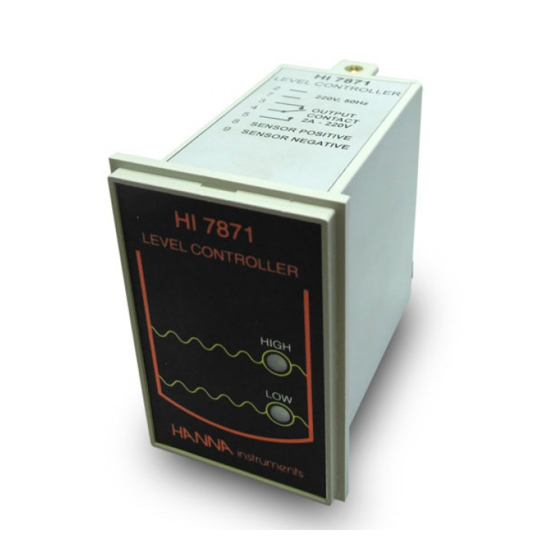
HI 7871- HI 7873
HI 7874
Level Controllers
w w w . h a n n a i n s t . c o m
WARRANTY
HI 7871, HI 7873 and HI 7874 are warranted for two years
against defects in workmanship and materials when used for their in-
tended purpose and maintained according to instructions. This warranty is
limited to repair or replacement free of charge.
Damages due to accident, misuse, tampering or lack of prescribed main-
tenance are not covered.
If service is required, contact the dealer from whom you purchased the
instrument. If under warranty, report the model number, date of purchase,
serial number and the nature of the failure. If the repair is not covered by
the warranty, you will be notified of the charges incurred. If the instrument
is to be returned to Hanna Instruments, first obtain a Returned Goods
Authorization Number from the Customer Service department and then
send it with shipment costs prepaid. When shipping any instrument, make
sure it is properly packaged for complete protection.
All rights are reserved. Reproduction in whole or in part is prohibited
without the written consent of the copyright owner, Hanna Instruments.
Hanna Instruments reserves the right to modify the design, construction
and appearance of its products without advance notice.
Dear Customer,
Thank you for choosing a Hanna product.
This manual will provide you with the necessary information
for a correct operation.
If you need additional technical information, do not hesitate
to e-mail us at tech@hannainst.com.
These instruments are in compliance with the
directives.
PRELIMINARY EXAMINATION
Remove the instrument from the packing material and exam-
ine it carefully. If any damage has occurred during shipment,
immediately notify your Dealer or the nearest Hanna Customer
Service Center.
Note: Conserve all packing material until the instrument has
been observed to function correctly. Any defective item
must be returned to the Dealer in its original packing.
GENERAL DESCRIPTION
HI 7871 and HI 7873 are 2-wire transmitter level controllers
designed especially for long distance control of liquid levels in
tanks (e.g. in biological and industrial water treatment).
A complete system should include:
• HI 7871 or HI 7873 level controller
• HI 7874 level transmitter & bar holder
• HI 7164 undecal connector
• 3 or 4 measuring bars
The level transmitter is basically a molded electrode holder
with 4 sockets to screw in the level sensors. The longest bar
has to be the common electrode and connected to the COM
port. The remaining bars can be connected in any sequence,
after cutting them to the required lengths.
HI 7874 contains a completely resinated amplifier circuit and
a 2-wire terminal board. It also comes with a mounting
bracket for quick and easy installation.
HI 7874 uses stainless steel measuring bars and employs 9V
peak to peak AC to measure the liquid level. It can be used
in liquids with conductivity greater than 10 µS/cm.
HI 7871 requires only 3 bars, whereas HI 7873 needs 4.
HI 7871 is a basic high and low level controller. HI 7873 has
an additional overflow alarm control.
FUNCTIONAL DESCRIPTION
FRONT PANEL
1
2
3
REAR PANEL
1. OVER LED (HI 7873 only)
indicates an overflow condition
2. HIGH LED indicates full tank
4
3. LOW LED indicates low liquid
level
4. 11-pin socket
MECHANICAL DIMENSIONS
FRONT VIEW
73mm
79mm
2.87"
3.11"
42mm
1.65"
49mm
1.93"
SIDE VIEW
0.25/4mm
ADJUSTABLE
0.01/0.160"
LOCATION
BRACKET
79mm
3.11"
76mm
3"
95mm MIN
3.74"
The supplied adjustable brackets allow the controller to slide
into the cut-out and hold the unit in place. 95 mm (3.74")
is the minimum space required to install the controller with
the cables connected.
SPECIFICATIONS
HI 7871
HI 7873
Transmission
max 100 m (330 feet)
Electrical Connection* HI 7164 undecal connector
Level Adjustment
high, low
high, low, overflow
Level Indication
high, low
high, low, overflow
Sensing Bars*
3
4
Transmitter*
HI 7874
Output Contact
1 relay
2 relays
(2A/250 Vac, 30Vdc)
Power Supply
110/115 Vac or 220/240 Vac; 50/60 Hz
Environment
0 to 50°C (32 to 122°F);
RH max 85% non-condensing
Dimensions
83 x 53 x 95 mm (3.1 x 1.9 x 3.7")
Weight
250 g (8.8 oz.)
* Not included with HI 7871 and HI 7873.
CONNECTIONS
• Remove the 11-pin connector from the rear of the level
controller.
• Connect a 2-wire power cable to terminals #2 and #7
(no ground connection).
• Connect the output terminals #4 (common) and #5
(low) to a relay switch (max 2A/230V) to start and stop
a pump or to open and close an electrovalve. These two
contacts act only as a switch and the pump or electrovalve
have to be powered independently.
Advertisement

Subscribe to Our Youtube Channel
Related Manuals for Hanna Instruments HI 7871


Summary of Contents for Hanna Instruments HI 7871
- Page 1 The remaining bars can be connected in any sequence, the warranty, you will be notified of the charges incurred. If the instrument is to be returned to Hanna Instruments, first obtain a Returned Goods after cutting them to the required lengths.
- Page 2 • Subsequently, when liquid level drops below the 3 bar, OPERATIONAL GUIDE CE DECLARATION OF CONFORMITY OVER LED goes off and HIGH LED comes on. When liquid level drops below the 2 bar, HIGH LED goes off. LOW • Turn on the power supply. After approx. 8 seconds, the LED lights up when the level drops below the 1 bar.
Need help?
Do you have a question about the HI 7871 and is the answer not in the manual?
Questions and answers