
Related Manuals for Hanna Instruments HI700 Series


Summary of Contents for Hanna Instruments HI700 Series
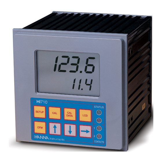
- Page 1 HI700 / HI710 Series Process, Panel-mounted, Microprocessor-based, Conductivity and TDS Controllers www.hannainst.com...
- Page 2 Dear Customer, Thank you for choosing a Hanna Instruments product. This instruction manual has been written for the following products: HI700221-α EC controller with dual setpoint, ON/OFF and PID controls, analog output. HI700222-α EC controller with dual setpoint, ON/OFF and PID controls, RS485 port.
-
Page 3: Table Of Contents
TABLE OF CONTENTS PRELIMINARY EXAMINATION ......4 GENERAL DESCRIPTION ......4 FUNCTIONAL DESCRIPTION . -
Page 4: Preliminary Examination
PRELIMINARY EXAMINATION Remove the instrument from the packing material and examine it carefully. For further assistance, please contact your local Hanna Instruments Office or email us at tech@ hannainst.com. Note Save all packing materials until you are sure that the instrument functions correctly. - Page 5 • Temperature compensation of the EC and TDS reading with temperature coefficient ß selectable from 0 to 10%/°C. • Manual temperature setting when the temperature probe is not inserted or temperature exceeds the upper range. • Last calibration data internally recorded (non-volatile EEPROM memory): calibration date and time, cell constant, calibration solution values.
-
Page 6: Functional Description
FUNCTIONAL DESCRIPTION FRONT PANEL 1. Liquid Crystal Display 2. SETUP key enters setup mode 3. CFM key confirms current choice (and skips to the next item) 4. CAL key initiates and exits calibration mode 5. key increases the blinking digit/letter by one when selecting a parameter. Advances forward while in last calibration data viewing mode. -
Page 7: Mechanical Dimensions
REAR PANEL 1. 6-pin RS485 terminal (HI700222 and HI710222 only) 2. Analog Output (HI700221 and HI710221 only) 3. Power Supply 4. Alarm Terminal 5. Contact 2 - Second Dosing Terminal 6. Timer 7. Hold 8. Contact 1 - First Dosing Terminal 9. -
Page 8: Specifications
SPECIFICATIONS 0.0 to 199.9 µS, 0 to 1999 µS 0.00 to 19.99 mS, 0.0 to 199.9 mS Ranges 0.0 to 100.0 ppm, 0 to 1000 ppm (HI710* only) 0.00 to 10.00 ppt, 0.0 to 100.0 ppt (HI710* only) -10.0 to 100.0 °C 0.1 µS, 1 µS, 0.01 mS, 0.1 mS 0.1 ppm, 1 ppm (HI 710 models only) Resolution... -
Page 9: Installation
INSTALLATION HI700 and HI710 series offer a multitude of possibilities, from single and dual setpoints to ON/OFF or PID dosage, isolated outputs with user-selectable zoom, bi-directional RS485, recorder outputs in mAmps and Volts. Use the 3-wire Pt 100 temperature sensor to compen- sate for the cable resistance and have a precise automatic temperature compensation of the... - Page 10 • Power Supply: Connect a 3-wire power cable to the terminal strip, while paying attention to the correct live (L), earth (PE) and neutral (N) terminal connections. Power: 115 Vac -100 mA / 230 Vac - 50 mA. Live Contact: fused inside 400 mA. PE leakage current 1 mA;...
- Page 11 Note All external cables to be connected to the rear panel should be ended with cable lugs. • Analog output: Connect an external recorder with a 2-wire cable to these terminals (#2 on page 7) paying attention to the correct polarity. A wide variety of output signals, either in V or in mA, is available to fit most standards.
-
Page 12: Setup Mode
SETUP MODE HI700 and HI710 offer a multitude of possibilities from ON/OFF or PID dosage to analog recorder output and from alarm to selftest features. The Setup Mode allows the user to set all needed characteristics of the meter. The setup mode is entered by pressing SETUP and entering the password when the device is in idle or control mode. - Page 13 Note The default password is set at “0000”. • The LCD will display “SET” on the upper part and “c.00” on the lower, allowing the user to edit setup parameters (see table below). • Enter the code of the parameter you want to set, using the arrow keys as per the password procedure above (e.g.
- Page 14 Code Valid Values Default 00 Factory ID 0 to 9999 0000 01 Process ID 0 to 99 02 Control enable/ 0: C.M. disabled disable 1: C.M. enabled 1: 0.0-199.9 µS (or 100.0 ppm) 03 Range 2: 0-1999 µS (or 1000 ppm) (depends on mode) 3: 0.00-19.99 mS (or 10.00 ppt) 4: 0.0-199.9 mS (or 100.0 ppt)
- Page 15 Code Valid Values Default PW 0.5 to 99.5% full scale 30 Relay 3 high alarm (HA) HA-Hys≥A+Hys,Hys=1.5%f.s. f.s. HA≥S1 or HA≥S2 0.5 to 99.5% full scale 31 Relay 3 low alarm (LA) LA+Hys+HA-Hys 5% f.s. Hys=1.5%fs,LA+S1 or LA+S2 32 Proportional control 1 to 30 min mode period 33 Maximum relay ON time...
- Page 16 Code Valid Values Default 75 Initial cleaning year 1998 to 9999 1998 76 Initial cleaning time 00:00 to 23:59 00:00 77 Cleaning ON interval 0 to 19999 minutes 0: off 90 Display selftest 1: on 0: off 91 Keyboard selftest 1: on 0: off 92 EEPROM selftest...
- Page 17 then S1-H1≥S2+H2, S2≥LA, HA≥S1; If M1 = 2 and M2 = 1 then S2-H2≥S1+H1, S1≥LA, HA≥S2; If M1 = 3 and M2 = 2 then S1≥S2+H2, S2≥LA, HA≥S1+D1; If M1 = 2 and M2 = 3 then S1+H1≤S2, S1≥LA, HA≥S2+D2; If M1 = 4 and M2 = 1 then S1≤S2–H2, S1–D1≥LA, HA≥S2;...
-
Page 18: Control Mode
CONTROL MODE The control mode is the normal operational mode for these meters. During control mode the meter fulfills the following main tasks: • converts information from EC/TDS and temperature inputs to digital values; • controls relays and generates the analog outputs as determined by the setup con- figuration, displays alarm condition;... - Page 19 Connect your device to the COM and NO (Normally Open) or NC (Normally Closed) terminals. The ON relay state occurs when relay is energized (NO and COM connected, NC and COM disconnected). The OFF relay state occurs when relay is de-energized (NO and COM disconnected, NC and COM connected).
- Page 20 During proportional control the process controller calculates the relay activation time at certain moments t etc. The ON interval (the shaded areas) is then dependent on the error amplitude. With the integral function (reset), the controller will reach a more stable output around the setpoint providing a more accurate control than with the ON/OFF or proportional action only.
- Page 21 Proportional action can be set by means of the Proportional Band (PB). Proportional Band is expressed in percentage of the input range and is related to Kp according to the following: Kp = 100/PB. Controller output Error Proportional Band The proportional action is set through the setup procedure as “Deviation” in percent of full scale of the selected range.
- Page 22 Note User can disable the derivative and/or integrative action (for P or PI controllers) by setting Td = 0 and/or Ti = MAX (Ti) respectively through the setup procedure. SIMPLE TUNING PROCEDURE The following procedure uses a graphical technique of analyzing a process response curve to a step input.
- Page 23 Note Connecting an external device (e.g. chart recorder) to the controller, the procedure is easier and doesn’t need the use of hand plotting the process variable (EC or TDS). ALARM RELAY The alarm relay functions in the following manner: FS•C = NO (Normally Open) Energized Relay FS•O = NC (Normally Closed) De-energized Relay...
- Page 24 The Fail Safe feature protects the process against critical errors arising from power interruptions, surges and human errors. This sophisticated yet easy-to-use system resolves these predicaments on two fronts: hardware and software. To eliminate problems of blackout and line failure, the alarm function operates in a “Normally Closed” state and hence alarm is triggered if the wires are tripped, or when the power is down.
-
Page 25: Idle Mode
IDLE MODE Idle mode is entered through setup code 2. During idle mode the device performs the same tasks as when it is in control mode except for the relays. The alarm relay is activated (no alarm condition), the control relays are not activated while the analog output remains activated. -
Page 26: Analog Output
Factory default is switches 1 and 3 closed (ON) and switches 2 and 4 open (OFF), i.e. 0-20 mA, 4-20 mA and 0-10 VDC. In any case, contact the nearest Hanna Instruments Customer Service Center for changing of the default configuration. - Page 27 Note The analog output is factory calibrated through software. The user may also perform the calibration procedure as explained in the following. It is recommended to perform the output calibration at least once a year. Note Analog output resolution is 1.5‰ f.s. with 0.5% f.s. accuracy. Note The analog output is “frozen”...
-
Page 28: Rs 485 Communication
HI92500. It is then possible to elaborate the data with your software (e.g. graphics, statistical analysis). To allow our users access to the latest version of Hanna Instruments PC compatible software, we made the products available for download at http://software.hannainst. - Page 29 CONNECTIONS The connections for the 6-pin RS485 terminal provided (#1 on page 7) are as follows: There is an internal short between the two A pins and between the two B pins. The instrument has no internal line termination. To terminate the line, an external resistor equal to the characteristic line impedance (typically 120Ω) must be added at both ends of the line.
- Page 30 The Fail-Safe resistors are connected only to one unit in the line, and their value depends on the application and characteristic impedance of the connection cable. The RS485 port is optoisolated from measuring circuit and power line. The analog output and RS485 port have the same ground.
- Page 31 Command Parameter Description null Request calibration data Request setup item NN null Same as CFM + +CAL keys null Same as LCD+CAL+SETUP keys null Same as CAL DATA key null Same as CFM key null Same as CAL key null Same as LCD key null Same as key...
- Page 32 Note If the controller is not in control or idle mode and the temperature reading is requested through the TMR command, the controller answers with the last acquired reading when it was in control or idle mode. Note After a recognized PWD command is received, the controller allows a maximum of 1 minute without receiving data, after which it locks again and a new PWD command is needed to perform password protected operations.
- Page 33 Following are examples of answers: 1) “03<STX>+01200<ETX>” The controller with process ID number 03 says that its current setpoint is +12.00 2) “01<STX>UE71022225<ETX>” The controller with process ID number 01 says that it is a HI710222 model with firmware release 2.5. The minimum delay between the last received character and first character of the answer is 15 ms.
- Page 34 If asking for last calibration data and the controller was never calibrated, it answers with “0”; e.g. “01<STX>0<ETX>”. If the controller was calibrated, it answers with “1” followed by the calibration data. The Data field of the answer has the following format: 1<Date><Time><CellCostant>...
-
Page 35: Calibration
The user should periodically calibrate the instrument for EC or TDS. For greatest accuracy, it is recommended that the instrument is calibrated frequently. Before beginning normal operation,it is recommended to standardize the probe with the Hanna Instruments calibration solution close to the expected sample value and inside the selected range. EC CALIBRATION... - Page 36 Offset Calibration • To perform the EC calibration enter the calibration mode, by pressing CAL and entering the password. • After the correct password is entered, the control actions stop and the primary LCD will display the first calibration value, with the “CAL” indicator blinking. The secondary LCD displays the temperature.
- Page 37 Note A 2-point calibration is always suggested. However the EC calibration can also be per- formed at 1 point. To calibrate offset only, just press CAL after confirmation (with CFM) of the zero reading; the meter will return to normal operational mode. To have the cell constant calibrated first, press the up or down arrow keys after entering the calibration procedure to skip to the next possible calibration buffer.
- Page 38 Note If the entered cell constant value is invalid, the “ERROR” indicator blinks on the LCD. Note Press SETUP before CFM to exit without changing the cell constant. CALIBRATION BUFFER DIRECT SELECTION This feature allows to set a user-defined calibration point, in order to perform calibration at a point different from the memorized standards.
- Page 39 • CAL will blink on the LCD. The measured tem- perature will be displayed on both the primary and secondary LCD. • Use the arrow keys to set on the secondary LCD the temperature read by the reference thermometer. • When the reading has stabilized at a value near the calibration point, CAL will stop blinking and an intermittent CFM will prompt the user to confirm the calibration.
- Page 40 • If everything is satisfactory the secondary LCD will display “20” for the second calibration point. • Set the mA simulator to 20 mA and wait for the reading to stabilize, CAL will stop blinking and an intermittent CFM will prompt the user to confirm the calibration. •...
- Page 41 • Execute the password procedure. • The primary display will show the current selected parameter blinking. Use the to select the code (0-5 see chart below) for the desired parameter displayed on the secondary display (e.g. 4-20 mA). • Press CFM to confirm the selected parameter that will stop blinking on the primary display.
- Page 42 • Wait for approximately 30 seconds (until the reading of the calibrator is stable). • Press CFM to confirm. The meter will switch to the second calibration point. Repeat the above procedure. • After the desired readings are obtained, press CFM and the meter will skip back to normal operational mode.
-
Page 43: Last Calibration Data
LAST CALIBRATION DATA The meter can display the following last calibration data: • Date • Time • Cell constant While displaying these data, the controller remains in control mode. The data are related to the selected range only. The procedure below indicates the flow. Displaying of the items follows the above sequence. -
Page 44: Fault Conditions And Selftest Procedures
FAULT CONDITIONS AND SELFTEST PROCEDURES The fault conditions below may be detected by the software: • EEPROM data error; • I2C internal bus failure; • date lost; • code dead loop. EEPROM data error can be detected through EEPROM test procedure at startup or when explicitly requested using setup menu. - Page 45 DISPLAY SELFTEST The display selftest procedure consists of lighting up all of the display segments together. The Display test is announced by a scrolling “Display test” message. The segments are lit for a few seconds and then switched off before exiting the selftest procedure.
- Page 46 For example, if CFM and CAL DATA are pressed together the LCD will look like this: The colon is a useful indicator for the correct position of squares. Note A maximum of two keys may be pressed simultaneously to be properly recognized. To exit the keyboard test procedure press LCD, CAL and SETUP simultaneously.
- Page 47 If is pressed the EEPROM selftest procedure terminates with no other action. Otherwise, EEPROM is reset with default values from ROM as when a device with a virgin EEPROM is switched on. During EEPROM reset a blinking message “Set” is shown on primary LCD;...
-
Page 48: External Functions
WATCHDOG When a dead loop condition is detected a reset is automatically invoked. The effectiveness of watchdog capability can be tested through one of the special setup items. This test consists of executing a dummy dead loop that causes watchdog reset signal to be generated. -
Page 49: Startup
STARTUP During the automatic startup the Real Time Clock (RTC) is checked to see if a reset occurred since last software initialization. In this case, the RTC is initialized with the default date and time 01/01/1998 - 00:00. An EEPROM reset does not affect the RTC settings. The EEPROM is also checked to see if it is new. -
Page 50: Ec Values At Various Temperatures
EC VALUES AT VARIOUS TEMPERATURES Temperature has a significant effect on conductivity. Table below shows EC values at various temperatures for the Hanna Instruments calibration solutions. TEMPERATURE EC VALUES (µS/cm) °C °F HI7030 HI7031 HI7033 HI7034 HI7035 HI7039 HI8030 HI8031 HI8033 HI8034 HI8035 HI8039... -
Page 51: Probe Maintenance
PROBE MAINTENANCE Probe can be compensated for normal contamination by a process of recalibration. When calibration can no longer be achieved, remove the conductivity probe from the system for maintenance. PERIODIC MAINTENANCE Inspect the probe and the cable. The cable used for the connection to the controller must be intact and there must be no points of broken insulation on the cable. -
Page 52: Accessories
ACCESSORIES CONDUCTIVITY CALIBRATION SOLUTIONS HI7030M 12880 µS/cm calibration solution, 230 mL bottle HI7030L 12880 µS/cm calibration solution, 500 mL bottle 12880 µS/cm calibration solution, 500 mL FDA HI8030L bottle HI7031M 1413 µS/cm calibration solution, 230 mL bottle HI7031L 1413 µS/cm calibration solution, 500 mL bottle 1413 µS/cm calibration solution, 500 mL FDA HI8031L bottle... - Page 53 PROBE CLEANING SOLUTIONS HI7061M General cleaning solution, 230 mL bottle HI8061M General cleaning solution, 230 mL FDA bottle HI7061L General cleaning solution, 500 mL bottle HI8061L General cleaning solution, 500 mL FDA bottle...
- Page 54 OTHER ACCESSORIES 4-ring conductivity probe with built-in 3-wire Pt100 temperature HI7639 sensor and 5 m (16.5’) cable 4-ring conductivity probe with standard 1/2’’ external thread HI3011 for flow-thru mounting and 3 m (10’) cable 4-ring conductivity probe with standard 1/2’’ external thread HI3012 for submersion applications and 3 m (10’) cable Stainless steel Pt100 probe with standard 1/2’’...
- Page 55 If the repair is not covered by the warranty, you will be notified of the charges incurred. If the instrument is to be returned to Hanna Instruments, first obtain a Returned Goods Authorization number from the Customer Service department and then send it with shipping costs prepaid.
- Page 56 World Headquarters Hanna Instruments Inc. Highland Industrial Park 584 Park East Drive Woonsocket, RI 02895 USA www.hannainst.com MANHI700 06/19 Printed in ROMANIA...
Need help?
Do you have a question about the HI700 Series and is the answer not in the manual?
Questions and answers