
Related Manuals for Hanna Instruments HI21 Series


Summary of Contents for Hanna Instruments HI21 Series
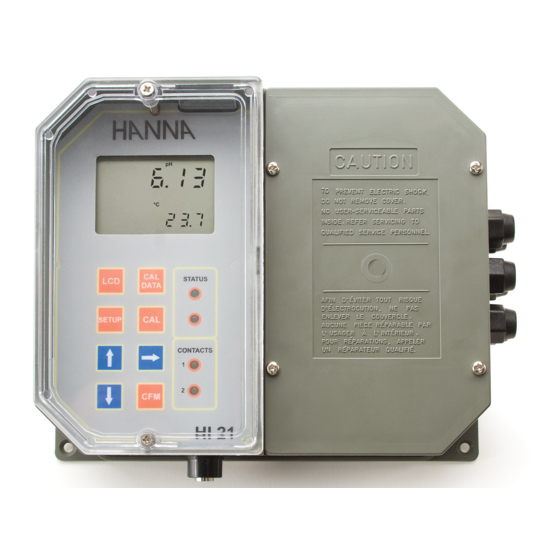
- Page 1 HI21 & HI22 Series Wall-mounted, Microprocessor-based pH and ORP Controllers Instruction Manual...
- Page 2 Dear Customer, Thank you for choosing a Hanna Instruments Product. Please read this instruction manual carefully before using the instrument. It will provide you with the necessary information for the correct use of the instrument, as well as a precise idea of its versatility.
-
Page 3: Table Of Contents
TABLE OF CONTENTS PRELIMINARY EXAMINATION ....4 GENERAL DESCRIPTION ..... . 4 FUNCTIONAL DESCRIPTION . -
Page 4: Preliminary Examination
• LEDs: three (HI22) or four (HI21) LEDs are provided for signaling the energizing of relay 1 (a yellow LED), relay 2 (a yellow LED in HI21 Series only) and alarm relays (a green and a red LED). • Relays: Electromechanical type, working through NO, COM and NC contacts;... - Page 5 • Internally recorded last calibration data (non-volatile EE- PROM memory): calibration date and time, pH offset, pH slopes, number of calibration points and correspondent pH values (for HI21 series only) or calibration date and time and the mV calibration points used (for HI22 series only).
-
Page 6: Functional Description
(in idle or control phases with the measure- ment on the display). In HI21 series, during pH calibration, alternately displays pH buffer value or current temperature 3. CAL DATA key last calibration data viewing (enters and exits) 4. -
Page 7: Mechanical Dimensions
CONNECTIONS PANEL 1. 4-pin RS485 terminal (not for HI21XY1 and HI22XY1) 2. Analog output (not for HI21XY2 and HI22XY2) 3. Connections for Pt 100 temperature sensor 4. ±5V power supply output 5. Connection for Potential Matching Pin 6. Connection for electrode reference 7. -
Page 8: Specifications Hi21 & Hi22
SPECIFICATIONS HI21 & HI22 0.00 to 14.00 pH (HI21 series only) Range ±2000 mV (HI22 series only) -9.9 to 120.0 °C 0.01 pH (HI21 Series only) Resolution 1 mV (HI22 Series only) 0.1 ˚C ±0.02 pH (HI21 Series only) Accuracy ±2 mV (HI22 Series only) -
Page 9: Installation
This can cause a rapid deg- radation of the electrode. The Hanna Instruments differential input reduces the likelihood of ground loops. See the diagram for a rec- ommended installation. - Page 10 • Power Supply: Connect a 3-wire power cable to the terminal strip, while paying attention to the correct line (L), earth (PE) and neutral (N) terminal connections. Power: 115VAC - 100 mA / 230VAC - 50 mA. Line Contact: fused inside 400 mA. PE must be connected to ground;...
-
Page 11: Setup Mode
SETUP MODE HI21 and HI22 offer a multitude of possibilities from ON/OFF, proportional or PID dosage to analog recorder output and from alarm to selftest features. The Setup Mode allows the user to set all needed charac- teristics of the meter. The setup mode is entered by pressing SETUP and entering the password when the device is in idle or control mode. - Page 12 • Then confirm the displayed digit with and move to the next one. • When the whole password has been inserted, press CFM to confirm it. Note The default password is set at “0000”. • The LCD will display “SET” on the upper part and “c.00”...
- Page 13 • After confirmation, the selected param- eter is displayed. The user can scroll through the parameters by pressing CFM. In order to directly set another pa- rameter, press SETUP again and enter the code or scroll to it by press- ing CFM.
- Page 14 Code Valid Values Default 23* Relay 2 hysteresis (H2) 0.00 to 14.00 pH 1 pH 0 to 4000 mV 50 mV 24* Relay 2 deviation (D2) 0.50 to 14.00 pH 1 pH 25 to 4000 mV 50 mV 25* Relay 2 reset time 0.1 to 999.9 minutes 999.9 mins (HI21523 only)
- Page 15 Code Valid Values Default 60 Current day 01 to 31 from RTC 61 Current month 01 to 12 from RTC 62 Current year 1997 to 9999 from RTC 63 Current time 00:00 to 23:59 from RTC 71 Baud rate 1200, 2400, 4800, 9600 9600 (RS485) 90 Display selftest 0: off...
- Page 16 If M1 = 2 and M2 = 3 then S1+H1<S2, S1>LA, HA>S2+D2; If M1 = 4 and M2 = 1 then S1<S2–H2, S1–D1>LA, HA>S2; If M1 = 1 and M2 = 4 then S1–H1>S2, S2–D2>LA, HA>S1; If M1 = 3 and M2 = 4 then S1>S2, S2–D2>LA, HA>S1+D1;...
-
Page 17: Control Mode
CONTROL MODE The control mode is the normal operational mode for these meters. During control mode HI21 and HI22 fulfill the fol- lowing main tasks: • convert information from pH/ORP and temperature inputs to digital values; • control relays and generate the analog outputs as deter- mined by the setup configuration, display alarm condition;... - Page 18 An upper boundary is imposed for acid/base dosage time when relays are energized continuously, i.e. when relay works in ON/OFF mode or in PID mode but in the latter case only if the relay is always ON. This parameter can be set through setup procedure.
- Page 19 P .I.D. CONTROL MODE (HI21523 ONLY) PID control is designed to eliminate the cycling associated with ON/OFF control in a rapid and steady way by means of the combination of the proportional, integral and deriva- tive control methods. With the proportional function, the duration of the activated control is proportional to the error value (Duty Cycle Control Mode): as the measurement approaches setpoint, the ON period diminishes.
- Page 20 An example of how the response overshoot can be improved with a proper rate action setting is depicted in the following graphic. PID TRANSFER FUNCTION The transfer function of a PID control is as follows: Kp + Ki/s + s Kd = Kp (1 + 1/(s Ti) +s Td) with Ti = Kp/Ki, Td = Kd/Kp, where the first term represents the proportional action, the second is the integrative action and the third is the deriva-...
- Page 21 In HI21 and HI22 the proportional action is set directly as “Deviation” in pH and mV units respectively. Relation between Deviation (D) and PB is: D = Range * PB/100 Each setpoint has a selectable proportional band: PB1 for setpoint1 and PB2 for setpoint2. Two further parameters must be provided for both setpoints: Ti = Kp/Ki, reset time, measured in minutes Td = Kd/Kp, rate time, measured in minutes.
- Page 22 1. Starting from a solution with a pH or mV value different from the dosed liquid (at least a 3 pH or 150 mV differ- ence) turn on the dosing device at its maximum capacity without the controller in the loop (open loop process). Note the starting time.
- Page 23 ALARM RELAY The alarm relay functions in the following manner: During alarm condition, the relay is de-energized. When not in alarm condition, the relay is energized. Example: High alarm set at 10 pH Low alarm set at 4 pH An hysteresis will eliminate the possibility of continuous sequences ‘energizing/de-energizing’...
- Page 24 This is an important feature since with most meters the alarm terminals close only when an abnormal situation arises, however, due to line interruption, no alarm is sounded, causing extensive damage. On the other hand, software is employed to set off the alarm in abnormal circumstances, for example, if the dosing terminals are closed for too long a period.
-
Page 25: Idle Mode
IDLE MODE During idle mode the device performs the same tasks as when it is in control mode except for the relays. The alarm relay is activated (no alarm condition), the acid and base relays are not activated while the analog output remains activated. -
Page 26: Analog Output
By default the minimum and maximum values of analog output correspond to the minimum and maximum of the range of the meter. For example, for the HI21 series with a selected analog output of 4-20 mA, the default values are 0.00 and 14.00 pH corresponding to 4 and 20 mA,... - Page 27 These values can be changed by the user to have the analog output matching a different pH range, for example, 4 mA = 3.00 pH and 20 mA = 5.00 pH. To change the default values, the setup mode must be en- tered.
-
Page 28: Rs485 Communication & Data Logging
To install HI92500 you need a 3.5” drive and few minutes to follow the instructions conveniently printed on the disk’s label. Contact your local Hanna Instruments Office to request a copy. SPECIFICATIONS The RS485 standard is implemented in HI21/HI22 with the... - Page 29 CONNECTIONS The connections for the 4-pin RS485 terminal provided (#1 on page 7) are as follows: The instrument has no internal line termination. To terminate the line, an external resistor equal to the characteristic line impedance (typically 120Ω) must be added at both ends of the line.
- Page 30 As additional feature, the controller is also provided with two pins (5V and 0V) in order to apply the Fail Safe Open Line protection method. To avoid erroneous readings in Open-Line conditions, pull- up and pull-down resistors should be connected as shown. The Fail-Safe resistors are connected only to one unit in the line, and their value depends on the application and characteristic impedance of the connection cable.
- Page 31 Command Parameter Description null Request calibration data Request setup item NN K 01 null Same as CFM++CAL keys K 02 null Same as LCD+CAL+SETUP keys null Same as CAL DATA key null Same as CFM key null Same as CAL key null Same as LCD key null...
- Page 32 Note If the controller is not in control or idle mode and the tem- perature reading is requested through the TMR command, the controller answers with the last acquired reading when it was in control or idle mode. Note After a recognized PWD command is received, the controller allows a maximum of 1 minute without receiving data, after which it locks again and a new PWD command is needed to perform password protected operations.
- Page 33 Note The controller answers to the GET command with the same data format explained in the SET command. Following are examples of answers: 1) “03<STX>-01200<ETX>” The controller with process ID number 03 says that its current setpoint is -1200 mV. 2) “01<STX>UHI2122210<ETX>”...
- Page 34 If asking for last calibration data and the controller was never calibrated, it answers with “0”; e.g. “01<STX>0<ETX>”. If the controller was calibrated, it answers with “1” followed by the calibration data. The Data field of the answer has the following format: HI21: 1<Date><Time><Offset><Slope1><Slope2 ><Buf1><Buf2><Buf3>...
-
Page 35: Calibration
(one-point calibration), but it is always good practice to calibrate in at least 2 points. pH CALIBRATION (for HI21 Series only) The pH controller can be calibrated through a one-point, two-point or three-point calibration. You do not need to... - Page 36 For accurate calibration, use two beakers for each buffer solution, the first one for rinsing the electrode, the second one for calibration. By doing this, contamination between the buffers is minimized. To obtain accurate readings, use pH7.01 and pH4.01 if you measure acidic samples, or pH7.01 and pH10.01 for alkaline measurements or perform a 3-point calibration for the entire range.
- Page 37 • Remove the protective cap from the pH electrode and immerse it into the selected buffer solution (e.g. pH7.01) with the Potential Matching Pin and temperature probe, then stir gently. Note The electrode should be submerged ap- proximately 4 cm (1½”) in the solution. The temperature probe should be located as close as possible to the pH electrode.
- Page 38 Two-point Calibration • Proceed as described above for one-point cali- bration, using pH7.01 as the first point, but do not quit calibration by pressing CAL at the end. Note The meter will automatically skip the buffer that was used for the first calibration to prevent errors. •...
- Page 39 Three-point Calibration • Proceed as described above but do not quit calibration by pressing CAL. Note The meter will automatically skip the two buffers that were used to prevent errors. • After the second calibration point is confirmed, immerse the pH electrode and the Potential Matching Pin into the third buffer solution (e.g.
- Page 40 CALIBRATION WITH MANUAL TEMPERATURE COMPENSATION • Enter the calibration procedure and press LCD to display the temperature on the secondary LCD. • Unplug any temperature probe that may be attached to the meter. The “°C” symbol will flash. • Note the temperature of the buffer solutions with a ChecktempC or another accurate ther- mometer with a resolution of 0.1 °C.
- Page 41 PH BUFFER SELECTION (HI21523 ONLY) A one point pH calibration at a value different from standard buffer is possible by directly entering the desired calibra- tion value. • Pour a small quantity of the calibration solution in a beaker and then press CAL to enter the calibration mode.
- Page 42 If offset is invalid the “WRONG” indicator will blink on the LCD. • The LCD will then show the default slope for Hanna Instruments elec- trodes: 57.5 mV/pH. Note If CAL DATA or LCD are pressed before CFM, calibration is aborted without changing the data of previous calibration.
- Page 43 mV INPUT CALIBRATION The pH/mV controller is factory calibrated for the mV and temperature inputs. However, the user may also perform a mV calibration. • Short the Connection for Potential Matching Pin (#5 on page 7) and the Connection for the Electrode Reference (#6 on page 7) with a jumper wire.
- Page 44 • When the reading has stabilized at a point near the first calibration point, CAL will stop blinking and an intermit- tent CFM icon will prompt the user to confirm the first calibration. • If the display stabilizes at a value significantly different from the first setpoint, an intermittent WRONG icon will prompt the user to check and...
- Page 45 • Use a Checktemp or another calibrated thermometer with a resolution of 0.1° as a reference thermometer. • Immerse the temperature probe in the beaker with ice and water as near to the Checktemp as possible. • Press and hold first CFM and then CAL to enter the temperature calibration mode.
- Page 46 • Immerse the temperature probe in the second beaker as near to the Checktemp as possible and repeat the above procedure. Calibration procedure may be interrupted by pressing CAL again at any time. If the calibration procedure is stopped this way, or if the controller is switched off before the last step, no calibration data is stored in non-volatile memory (EEPROM).
- Page 47 • Press CFM to confirm the parameter that stops blinking on the primary display. The secondary display shows the multimeter or HI931002 input value as the interval lower limit. • Use or to make the HI931002 or multimeter output correspond with the value shown on the secondary display (e.g.
-
Page 48: Last Calibration Data
LAST CALIBRATION DATA The meter stores the following information about last cali- bration in the EEPROM: • Date • Time • Offset in mV (for HI21 only) • Up to two slopes (for HI21 only) • Up to three buffers While displaying this data, the pH controller remains in control mode. - Page 49 Note In any moment, by pressing LCD or CAL DATA the meter will return to the regular operating display. • Press or to view the time of last calibration. The secondary display will show "HOU" to indicate hours. •...
- Page 50 • Press or again to view the second memorized buffer at the time of last calibration. The secondary display will show "BUF2" to indicate second buffer. • Press or again to view the third memorized buffer at the time of last calibration.
-
Page 51: Start-Up
START-UP At start-up the firmware release code scrolls through the LCD; it is possible to escape from code scrolling pressing any key. During the automatic start-up the Real Time Clock (RTC) is checked to see if a reset occurred since last software initialization. -
Page 52: Fault Conditions And Selftest Procedures
FAULT CONDITIONS AND SELFTEST PROCEDURES The fault conditions below may be detected by the software: • EEPROM data error; • I2C internal bus failure; • code dead loop. EEPROM data error can be detected through EEPROM test procedure at start-up or when explicitly requested using setup menu. - Page 53 The error detection for dead loops is performed by watch- dog (see below). You can use special setup codes, perform selftest procedures for LCD, keyboard, EEPROM, relays and LEDs, watchdog. The operation of these functions is outlined in the setup section.
- Page 54 The colon is a useful indicator for the correct position of squares. Note A maximum of two keys may be pressed simultaneously to be properly recognized. To exit the keyboard test procedure press LCD, CAL and SETUP simultaneously. EEPROM SELFTEST The EEPROM selftest procedure involves verifying the stored EEPROM checksum.
- Page 55 RELAYS AND LEDS Relays and LEDs selftests are executed as follows: First all of the relays and LEDs are switched off, then they are switched on one at a time for a few seconds and cyclically. User can interrupt the otherwise endless cycle, as indicated by the scrolling message, by pressing a key.
-
Page 56: Ph Values At Various Temperatures
pH VALUES AT VARIOUS TEMPERATURES Temperature has a significant effect on pH. The calibration buffer solutions are effected by temperature changes to a lesser degree than normal solutions. For manual temperature calibration please refer to the following chart: TEMP. pH VALUES ˚C ˚F 4.01... -
Page 57: Electrode Conditioning And Maintenance
ELECTRODE CONDITIONING AND MAINTENANCE * Only available with refillable electrodes. For industrial applications, gel-filled electrodes are preferable due to lesser maintenance requirements. PREPARATION Remove the protective cap. DO NOT BE ALARMED IF ANY SALT DEPOSITS ARE PRES- ENT. This is normal with electrodes and they will disappear when rinsed with water. - Page 58 If the bulb and/or junction are dry, soak the electrode in HI70300 storage solution for at least one hour. For refillable electrodes**: If the refill solution (electrolyte) is more than 2½ cm (1”) below the fill hole, add HI7082 3.5M KCl Electrolyte Solution for double junction or HI7071 3.5M KCl+AgCl electrolyte solution for single junction electrodes.
- Page 59 Soak in Hanna Instruments HI7074 inorganic Inorganic cleaning solution for 15 minutes. Oil/grease Rinse with Hanna Instruments HI7077 Oil & Fat cleaning solution. IMPORTANT After performing any of the cleaning procedures rinse the electrode thoroughly with distilled water, drain and refill the...
- Page 60 - Make sure cable and connections are not damaged nor lying in a pool of water or solution. • Slow Response/Excessive Drift: Soak the tip in Hanna Instruments solution HI7061 for 30 minutes, rinse thoroughly in distilled water and then follow the Cleaning Procedure above.
-
Page 61: Taking Redox Measurements
TAKING REDOX MEASUREMENTS Redox measurements allow the quantification of the oxidiz- ing or reducing power of a solution, and are commonly expressed in mV. Oxidation may be defined as the process during which a molecule (or an ion) loses electrons and reduction as the process by which electrons are gained. - Page 62 Reducing pretreatment: immerse the electrode for a few minutes in HI7091. Oxidizing pretreatment: immerse the electrode for a few minutes in HI7092. If the pretreatment is not performed, the electrode will take significantly longer to respond. As with pH electrodes, gel-filled redox electrodes are more suitable for industrial applications due to lesser maintenance requirements.
-
Page 63: Accessories
ACCESSORIES pH CALIBRATION SOLUTIONS HI7004M pH4.01 buffer solution, 230 mL bottle HI7004L pH4.01 buffer solution, 500 mL bottle HI7004/L pH4.01 buffer solution, 1 L bottle HI7007M pH7.01 buffer solution, 230 mL bottle HI7007L pH7.01 buffer solution, 500 mL bottle HI7007/L pH7.01 buffer solution, 1 L bottle HI7010M pH10.01 buffer solution, 230 mL bottle... - Page 64 RECOMMENDED pH ELECTRODES (all electrodes are gel-filled and with ce- ramic junction unless otherwise indicated). HI1090T Screw connector, external PG13.5 thread, double junction, glass body, polymer filled HI1210T Screw connector, external PG13.5 thread, double junction, HI1211T Plastic body; cloth junction (HI 1210T); PVDF junction, polymer-filled (HI1211T) HI2910B/5 BNC connector, 5 m (16.5’) cable, double junction, plastic...
- Page 65 PLATINUM ORP ELECTRODES HI3090T Screw connector, external PG13.5 thread, double junction, Pt, glass body, polymer filled HI3210T Screw connector, external PG13.5 thread, double junction, Pt, plastic body, cloth junction HI3211T Screw connector, external PG13.5 thread, double junction, Pt, plastic body, PVDF junction, polymer-filled HI2930B/5 BNC connector, 5 m (16.5’) cable, double junction, Pt, plastic body with built-in amplifier and external thread, cloth...
- Page 66 HI3210B/5 BNC connector, 5 m (16.5’) cable, double junction, Pt, plastic body, PVDF junction, polymer-filled GOLD ORP ELECTRODES HI4932B/5 BNC connector, 5 m (16.5’) cable, double junction, Au, plastic body with built-in amplifier and external thread ELECTRODES FOR HIGH PRESSURE APPLICATIONS pH ELECTRODES ½‘’...
- Page 67 ORP ELECTRODES ½‘’ thread, double PVDF junction, polymer filled, max operating pressure of 6 bar (87 psi) PLATINUM ELECTRODES Part Code Matching Pin Amplifier Connector Cable HI2002/3 3 m (10’) HI2002/5 5 m (16.5’) HI2003/3 BNC* 3 m (10’) HI2003/5 BNC* 5 m (16.5’) HI2004/5...
- Page 68 OTHER ACCESSORIES BL PUMPS Dosing pumps with flow rate from 1.5 to 20 LPH HI98501 ChecktempC Electronic thermometer (range -50.0 to 150.0 °C) HI98502 ChecktempF Electronic thermometer (range -58.0 to 302 °F) HI6050 & HI 6051 Submersible electrode holders HI6054 & HI 6057 Electrode holders for in-line applications HI778P Screened coaxial cable with screw connectors...
-
Page 69: Warranty
Damage due to accident, misuse, tampering or lack of prescribed maintenance are not covered. If service is required, contact your local Hanna Instruments Office. If under warranty, report the model number, date of pur- chase, serial number and the nature of the failure. -
Page 70: Ce Declaration Of Conformity
CE DECLARATION OF CONFORMITY Recommendations for Users Before using these products, make sure that they are entirely suitable for the environment in which they are used. Operation of these instruments in residential areas could cause unaccept- able interferences to radio and TV equipment. To maintain the EMC performance of equipment, the recommended cables noted in the user’s manual must be used. - Page 71 New reference material is constantly being added to the library. For these and others catalogs, handbooks and leaflets, contact your local Hanna Instruments Office. To find the Hanna Instruments Office in your vicinity, check our home page at www.hannainst.com...
- Page 72 TECHNICAL SERVICE CONTACTS Australia: Tel. (03) 9769.0666 • Fax (03) 9769.0699 China: Tel. (10) 88570068 • Fax (10) 88570060 Egypt: Tel. & Fax (02) 2758.683 Germany: Tel. (07851) 9129-0 • Fax (07851) 9129-99 Greece: Tel. (210) 823.5192 • Fax (210) 884.0210 Indonesia: Tel.
Need help?
Do you have a question about the HI21 Series and is the answer not in the manual?
Questions and answers