Hanna Instruments HI 720 Instruction Manual
Conductivity process controller with inductive probe
Hide thumbs
Also See for HI 720:
- Instruction manual (2 pages) ,
- Manual (2 pages) ,
- Instruction manual (2 pages)
Table of Contents
Advertisement
Quick Links
Advertisement
Table of Contents

Related Manuals for Hanna Instruments HI 720


Summary of Contents for Hanna Instruments HI 720
- Page 1 Instruction Manual HI 720 Conductivity Process Controller with Inductive Probe...
-
Page 3: Table Of Contents
TABLE OF CONTENTS WARRANTY ......................4 PRELIMINARY EXAMINATION ................5 MODEL IDENTIFICATION ..................5 GENERAL DESCRIPTION & THEORY OF OPERATION .........6 SPECIFICATIONS .....................9 FUNCTIONAL DESCRIPTION ................10 INSTALLATION ....................12 OPERATIONAL GUIDE ..................14 • SETUP MODE ...................14 • CALIBRATION MODE ................34 • CONTROL MODE ..................37 •... -
Page 4: Warranty
If the repair is not covered by the warranty, you will be notified of the charges incurred. If the instrument is to be returned to Hanna Instruments, first obtain a Returned Goods Authorization number from the Customer Service department and then send it with shipping costs prepaid. -
Page 5: Preliminary Examination
Any damaged or defective items must be returned in their original packing materials together with the supplied accessories. MODEL IDENTIFICATION The models HI 720 XYZ-α are conductivity controllers. The meaning of the last letters is according to the following scheme:... -
Page 6: General Description & Theory Of Operation
GENERAL DESCRIPTION & THEORY OF OPERATION This instrument allows conductivity measurements without any electrical contact between electrodes and process fluid. The measurement is based on inductive coupling of two toroidal transformers by the liquid. The instrument supplies a high frequency, reference voltage to the “Drive Coil”, and a strong magnetic field is generated in the toroid. - Page 7 For an inductive cell, the cell constant is defined as the measured conductivity, obtained by making a loop through the sensor with a resistor R, multiplied by that R value. The cell constant depends only on the sensor geometry. However, when the probe is immersed in a liquid, the induced current in the solution is affected by the piping or any other container where the probe is inserted.
- Page 8 The main features of the HI 720 controller series include: • Measurement and control of conductivity or concentration • Concentration can be measured as usual TDS (fixed ratio) or through custom conductivity/temperature/concentration curves • Customizing temperature coefficient table and NaCl temperature compensation according to IEC 746-3, in addition to the standard linear compensation •...
-
Page 9: Specifications
SPECIFICATIONS Range 0 to 2000 mS/cm (auto-ranging) -30 to 130°C / -22 to 266°F Resolution 1 µS/cm (0 to 1999 µS/cm) 0.01 mS/cm (2.00 to 19.99 mS/cm) 0.1 mS/cm (20.0 to 199.9 mS/cm) 1 mS/cm (200 to 2000 mS/cm) 0.1°C / 0.2°F Accuracy ±2% f.s. -
Page 10: Functional Description
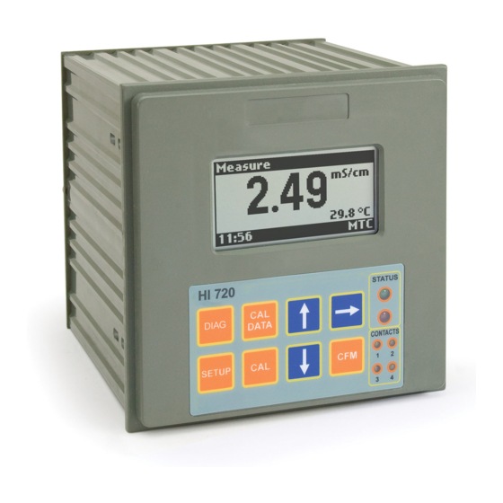
FUNCTIONAL DESCRIPTION Graphic display (128 x 64 dots) DIAG key, to enter/exit diagnostic mode; to change the conductivity or concentration range while in setup or calibration mode SETUP key, to enter/exit setup mode CAL DATA key, to enter/exit last calibration data viewing mode CAL key, to enter/exit calibration mode ... - Page 11 Connections for conductivity probe Connections for Pt100/Pt1000 temperature sensor Digital Transmitter input Hold input Advanced Cleaning input (optional) RS485 output terminal Hold output Analog output #1 Analog output #2 (optional) Power supply input Relay #3 - for Advanced Cleaning feature (optional) Relay #4 - for Advanced Cleaning feature (optional) Relay #1 - first dosing terminal Relay #2 - second dosing terminal (optional)
-
Page 12: Installation
INSTALLATION Mechanical Dimensions Electrical Connections • Power Input: connect a 3-wire power cable to the line (L), earth (PE) and neutral (N) terminal connections. Power: 100 Vac-120 mA / 115 Vac-100 mA / 230 Vac-50 mA. Line Contact: 400 mA fuse inside. PE must be connected to ground;... - Page 13 It is also possible to use a separate Pt100/Pt1000 temperature probe. In the case of shielded wire, connect the shield to pin 4. In the case of a 2-wire sen- sor connect the Pt100/Pt1000 to pins 1 and 3, and short pins 2 and 3 with a jumper wire.
-
Page 14: Operational Guide
OPERATIONAL GUIDE The HI 720 process controller can operate in six main modes: • Setup mode • Calibration mode • Control mode • Idle mode • Last calibration data viewing mode • Diagnostic mode (active errors & event log file scrolling) All operating modes are described in the following sections. - Page 15 The user can choose the desired parameter with the up & down arrow keys, and confirm the selection by pressing CFM. Note For some groups, it is necessary to enter several sublevels before choosing a parameter value. Follow the displayed messages to pro- ceed, confirm or exit each screen.
- Page 16 This table lists all available setup items together with their code, short description, valid values and default setting. Setup Item Description Valid Values Default GENERAL SETTINGS G.00 Measurement mode Conductivity, Conductivity (see note 8) Concentration, TDS G.01 Conductivity range Auto range, Auto range 1999 µS/cm, 19.99 mS/cm,...
- Page 17 Setup Item Description Valid Values Default TEMPERATURE b.03 Temperature measure °C, °F °C unit (see note 32) b.10 Temp. compensation Linear, Linear algorithm (note 28) NaCl (IEC 746, table BII) User: user defined table b.11 Reference temp. 20°C, 25°C 25°C (see note 28) b.12 Temp.
- Page 18 Setup Item Description Valid Values Default Curve 1/2/3/4 Table (see note 34) d.03 Not compensated 0 to f.s. 0 µS/cm conductivity value for the triplet selected in d.02 d.04 Temperature value for -30.0 to 130.0°C 0.0°C the d.02 triplet d..05 Concentration value 0 to f.s 0 ppm...
- Page 19 Setup Item Description Valid Values Default Setpoint 2 C.24 Setpoint 2 reset time 0.1 to 999.9 minutes 999.9 min. C.25 Setpoint 2 rate time 0.0 to 999.9 minutes 0.0 min. Alarms C.30 Low alarm value 0 to f.s 100 µS/cm (LA) (see note 18) (see note 1) C.31...
- Page 20 Setup Item Description Valid Values Default Other Parameters C.70 Hold mode end delay 00 to 99 seconds 00 sec C.80 On/Off control 00:00 to 30:00 min. 00:00 min action delay (note 26) OUTPUT Relays O.01 Relay 1 mode Disabled, Control- (see notes 16, 17) Control-setpoint 1, setpoint 1...
- Page 21 Setup Item Description Valid Values Default Analog Output 1 O.13 Analog output 1 0 to f.s. 1999 µS/cm maximum value (O_VARMIN1 ≤ (O_VARMAX1) O_VARMAX1 -5% f.s. for O_VARMAX1, O_VARMIN1 ≤ O_HOLD1 ≤ O_VARMAX1) O.14 Analog output 1 User selected value, Previous value hold mode (note 13) Previous value O.15 Analog output 1...
- Page 22 Setup Item Description Valid Values Default INPUT I.00 Input selection Inductive probe or Inductive (note 10) Digital transmitter probe I.03 Digital transmitter 00 to 99 address (active if I.00=Digital transmitter) I.04 Digital transmitter 1200, 2400, 4800, 19200 bps baud rate 9600 or 19200 bps I.10 Calibration timeout...
- Page 23 Setup Item Description Valid Values Default COMMUNICATION P .14 Remaining SMS 000 to 200, or 222 (see note 22) P .15 Repeated SMS 0 to 5 (see note 23) P .16 SMS delay between 05 to 60 minutes 10 minutes messages (see note 24) P .17 SIM card expiration...
- Page 24 Setup Item Description Valid Values Default ERROR CONFIGURATION E.01 Low alarm (01) Alarm relay -------------> On 22 mA fault current----> Off 3.6 mA fault current---> On Auto cleaning ----------> Off SMS sending -----------> Off E.02 Max relay ON time Alarm relay -------------> On error (02) 22 mA fault current---->...
- Page 25 Setup Item Description Valid Values Default ERROR CONFIGURATION E.21 Temperature level Alarm relay -------------> On error (21) 22 mA fault current----> On 3.6 mA fault current---> Off SMS sending -----------> Off E.40 Digital transmitter Alarm relay -------------> On error (40) 22 mA fault current---->...
- Page 26 Setup Item Description Valid Values Default ERROR CONFIGURATION E.91 EEPROM corruption Alarm relay -------------> On (91) 22 mA fault current----> On 3.6 mA fault current---> Off SMS sending -----------> Off E.92 Watchdog error Alarm relay -------------> Off (92) 22 mA fault current----> On 3.6 mA fault current--->...
- Page 27 NOTES: M1 can not be set to “On/Off high” or “On/Off low” if O.10 is set to “Control-setpoint 1” and vice versa. 0 ≤ LA + AH < HA - AH ≤ f.s. if M1 = “PID high”, then S1 + D1 ≤ HA - AH if M1 = “PID low”, then S1 - D1 ≥ LA + AH if M1 = “On/Off high”, then S1 - H1 ≥ LA + AH if M1 = “On/Off low”, then S1 + H1 ≤ HA - AH M2 can not be set to “On/Off high” or “On/Off low” if O.20 is set to “Control-setpoint 2”...
- Page 28 When a wrong setup code or value is confirmed, the controller does not move from the current window, and displays a blinking WRONG message till the user changes the value. Note that the allowed values for some parameters depend from other settings (e.g. to set a high setpoint to 10.00 mS, first set the high alarm to a value greater than 10.00 mS).
- Page 29 Error Alarm 22 mA 3.6 mA Hold Auto- S M S Config. Relay fault curr. fault curr. mode cleaning sending Note that the values in this table are used for error configuration through RS485. The hold mode is never enabled by the control timing if the “hold time start”...
- Page 30 TDS values in setup (excluding the temperature compensation table and the concentration curves) are automatically updated, so that the “new value / new f.s.” = “previous value / previous f.s.“ A life check error is generated if the reading does not vary more than 0.5% of the current f.s.
- Page 31 (17) If the relay 1 (or relay 2) mode is set to “Control-setpoint 1”, the analog output 1 can not be set to “Control-setpoint 1”, and vice versa. Similarly, if the relay 1 (or relay 2) mode is set to “Control-setpoint 2”, the analog output 2 can not be set to “Control-setpoint 2”, and vice versa.
- Page 32 If the item P .14 has been set to “222”, no expiration date check will be done. (26) This item is particularly useful in noisy environment, to filter measurement spikes and avoid undesired activations of the on/off control contacts. The relay energizes and de-energizes only if the corresponding threshold is overridden for more than the configured contact action delay (see below graph: “dly”...
- Page 33 (30) This parameter set the number of latest measurements used to calculate an average value. The average is calculated both for conductivity/concentration and temperature. The averaged conductivity/concentration value is then used both for displaying and control. (31) When the concentration unit is changed, all items from C.00 to C.34 and from O.12 to O.15 are reset to the default values.
-
Page 34: Calibration Mode
alibration The controller is factory calibrated for temperature as well as for the analog outputs. The user should periodically calibrate the instrument for the conductivity range. For greatest accuracy, it is recommended to standardize the probe with a cali- bration solution close to the expected sample value. •... - Page 35 zero calibration, and the “Wait ...” message will flash on the LCD. After com- pleting the procedure, the meter will ask for confirmation to proceed with the previously selected calibration point. • Press CFM to confirm and immerse the conductivity probe & temperature sen- sor (if a separate temperature probe is used) in the proper calibration solution.
- Page 36 • Use a Checktemp or another calibrated thermometer with a resolution of 0.1° as reference thermometer, and immerse the temperature sensor in the ice bath as near to the Checktemp as possible. • Confirm the calibration option and the instrument will start the automatic cali- bration of the first point.
-
Page 37: Control Mode
The control mode is the normal operational mode for this meter. During control mode HI 720 fulfills the following main tasks: • convert information from conductivity and temperature inputs to digital values, and show them on the display • control relays and generate the analog outputs as determined by the setup configuration •... - Page 38 If the “hold mode” is selected for the relay, then it is energized only when the meter is in hold mode. In this case there is no time boundary for the relay ON state. Relays 3 and 4 can be configured to operate in three modes: 1.
- Page 39 “trial & error” tuning procedure must be applied to get the best possible control for each process. The target is to achieve a fast response time and a small overshoot. Many tuning procedures are available and can be applied to HI 720.
- Page 40 A simple and profitable procedure is described in this manual and can be used in almost all applications. The user can vary five different parameters, i.e. setpoint value (S1 or S2), devia- tion (D1 or D2), reset time, rate time and proportional control mode period T Note The user can disable the derivative and/or integrative action (for P or PI controllers) by setting Td = 0 and/or Ti = MAX (Ti), respectively,...
- Page 41 Example: • Max. slope = 30 mS / 5 min = 6 mS/min • Time delay = Tx = approx. 7 minutes • Deviation = Tx * 6 = 42 mS • Ti = Tx / 0.4 = 17.5 min •...
- Page 42 The Fail Safe mode is accomplished by connecting the external alarm circuit between the FS•C (Normally Open) and the COM terminals. This way, an alarm will warn the user when measurement overtakes the alarm thresholds, power fails, or the wire connecting the process meter with the external alarm circuit breaks. Note To activate the Fail Safe feature, an external power supply must be connected to the alarm device.
-
Page 43: Idle Mode
While in idle mode, the device only performs measurements. It does not activate relays or generate a control signal to the analog output(s). In a normal situation the alarm relay is energized (no alarm condition) and the green LED is ON. The red LED is also fixed ON to warn users the device is not controlling the process, while the yellow LEDs are OFF. -
Page 44: Diagnostic Mode
iagnoStiC The diagnostic mode allows the user to check if some errors are still active on the controller, or view the event log file. To enter (and exit at any time) this mode, press the DIAG key. Select the desired option with the up & down arrow keys, and then confirm the selection by pressing CFM. - Page 45 3. Configuration changes: setup group, setup pa- rameter, date & time of the modification, previous value, new value. If the description of the previous and/or new val- ue is too long to be displayed, an index between square brackets is used. This index indicates the position of the value in the list of available op- tions for the parameter.
-
Page 46: Temperature Compensation
TEMPERATURE COMPENSATION If the setup item b.01 is set to ATC, then an automatic temperature compensa- tion of the conductivity readings will be performed using the temperature values acquired through the Pt100/Pt1000 input. If the temperature probe is not connected or it provides an invalid temperature (outside the -30 to 130°C range), the instrument will generate a “broken tem- perature probe”... - Page 47 Up to 10 actual conductivity/temperature couples can be entered to define the curve for the temperature compensation. The default values for the temperature compensation table are: Couple Actual Conductivity Temperature 500 µS/cm 0.0 °C 600 µS/cm 5.0 °C 700 µS/cm 10.0 °C 800 µS/cm 15.0 °C...
-
Page 48: Concentration Curves
CONCENTRATION CURVES The instrument allows the user to insert up to 4 con- centration tables, and each table is defined by up to 25 triplets of conductivity (K), temperature (T) and concentration (C) values. Note that all conductivity values in this section are actual values (i.e. - Page 49 • C is the concentration corresponding to the conductivity K at the temperature , and T is the temperature of the isotherm just above T The diagram shows the computational proce- dure. Note If T is greater than all temperature values specified for the isotherms, then the concentration value C (K ) is assigned to C (where...
-
Page 50: Hold Mode
HOLD MODE This function is started by: • calibration • setup • cleaning in place • the hold digital insulated input (there are two digital insulated inputs: one for hold mode and one for the advanced cleaning) when it is on; normally the signal level is polled at least every 4 seconds •... - Page 51 After the cause which made the instrument enter the hold mode expires, the device exits the hold mode, but control and alarms remain disabled for a user-selectable delay (0 to 99 seconds). In that situation, measurements are normally acquired, displayed and recorded through the analog or RS485 output. Note Alarms (alarm relay, red LED, fault currents) are not disabled if the hold mode has been triggered by an error and no other trigger source...
-
Page 52: In-Line Cleaning
IN-LINE CLEANING The cleaning feature allows an automatic cleaning action of the electrodes. To perform cleaning, the controller activates an external device (pump). Cleaning actions never take place if no relay is configured for cleaning. Moreover, the Advanced Cleaning requires both relays 3 and 4 to be configured for it. Cleaning can be of two types: •... - Page 53 • Hold mode end delay: if the device was controlling, then the hold mode end delay must expire before restarting control. If the device is in normal measurement mode, when performing a cleaning action, the display shows a countdown for the seconds remaining to the cleaning action end, and starting with the total cleaning time.
-
Page 54: Communication
It also has an on-line help feature to support you throughout all operations. The readings logged into the HI 720 internal memory can be downloaded through HI 92500, which makes it possible for you to use the powerful means of the most diffused spreadsheet programs. - Page 55 (typically an industrial PLC or PC). Each HI 720 unit is identified by its Process ID number (00 to 99), which corre- sponds to the Process ID configured through the setup item G.11.
- Page 56 RS485 Protocol for HI 720 Commands are composed of four parts: address, command identifier, parameter, end of command. The end of command corresponds to the CR char (0x0d). Some commands are used when the master is requesting information from the controller, others when the master wants to set a parameter in the process memory (RAM or EEPROM).
- Page 57 Command Parameter Remarks CNNP Sets setup item C.NN (e.g. “r.01”) with parameter P (*) (not available if the controller is in setup mode) not available Requests the event log file (not available if the controller is in setup mode) not available Requests new event log file (not available if the controller is in setup mode) not available...
- Page 58 b.33, d.03: if range is 1999 µS/cm if range is 19.99 mS/cm if range is 199.9 mS/cm if range is 2000 mS/cm C.11, C.12, C.13, C.21, C.22, C.23, C.30, C.31, C.34, O.12, O.13, O.15: if G.00 = “Conductivity” or “TDS” if range is 1999 µS/cm or 1000 ppm if range is 19.99 mS/cm or 10.00 ppt if range is 199.9 mS/cm or 100.0 ppt...
- Page 59 C.10, C.20 Disabled = OFF On/Off high = OOHI ; On/Off low = OOLO PID high =PIdH ; PID low = PIdL O.01, O.02 Disabled = OFF Control-setpoint 1 = SEt1 Control-setpoint 2 = SEt2 Simple cleaning = SCLE Hold mode = HOLd O.03, O.04 Disabled = OFF Simple cleaning = SCLE...
- Page 60 For all items with a fixed set of choices, blank spaces on the left of the value displayed are replaced with “*” (as many “*” characters are needed to reach the maximum string length, which is for example 3 for item C.57). Blanks must be put on the tail for all items in order to have always a total length of 6 characters (see the setup table for item lengths).
- Page 61 the first HI 92500 software version compatible with the firmware, even if it may not be able to exploit all the features of the firmware, e.g. “34” for 3.4; CD is the first HI 92500 software version fully compatible with this firmware, e.g. “45” for 4.5. The HOP request produces the following answer: “NN<STX>C <ETX>”...
- Page 62 Examples of answer to the ECR command are: • NN<STX>02.16mSC<ETX>= 2.16 mS/cm, control is ON & alarm is OFF • NN<STX>1886uSN<ETX>= 1886 µS/cm, control is OFF • NN<STX>00.94pptA<ETX>= 0.94 ppt, control and alarm are ON • NN<STX>>>>.>mSN<ETX>= overflow (range 199.9 mS/cm), control is OFF The answer to the TMR command is: “NN<STX><ascii string for a float>S<ETX>”...
- Page 63 bit 4 setup updated (set to 1 after a device power-up, device reset or a change in setup made through instrument keyboard; reset to 0 after receiving a GET command) bit 5 calibration mode (set to 1 after a device power-up or whatever complete calibration;...
- Page 64 The meaning of “start_date ” and “start_time ” is: • for errors: date and time at which the error was generated • for setup events: date and time of a setup item change • for calibration events: date and time of a calibration •...
- Page 65 desD (calibration) USED FOR COND. CALIBRATION ONLY Cell constant or installation factor value desD (cleaning) Not used Events are logged in the event log file in chronological order, i.e. record number 1 refers to the oldest event. When the event log file is full, the oldest event is replaced with the oncoming one.
- Page 66 bit 1 Temperature outside the user concentration table bit 2 Conductivity outside the user concentration table bit 3 Concentration outside the user concentration table bit 4 free for future use (and set to 0) bit 5 free for future use (and set to 0) bit 6 free for future use (and set to 0) bit 7...
-
Page 67: Short Messaging Service (Sms)
HI 504901). This connection enables the instrument to send SMS to one (or two) cellular phone(s) and through this feature the device can be monitored at any moment. Moreover, if an error occurs on the HI 720, it is possible to receive an alarm SMS which immediately advises about the problem. - Page 68 HI 720 and an SMS is on the way. When an alarm SMS is sent, then the instrument waits for a confirmation by the user of message reception.
- Page 69 stood as an information request. The instrument will hang up the call and send an SMS about its current status (number of remaining messages, currently measured values and active errors). The message will be, for example: “Rem_msg: 150; 1832 uS/cm; 025.8C; Err: xxxxx, xxxxx” Each message is made of a maximum of 160 characters.
- Page 70 It is also possible to ask information (about current readings and active errors) to the HI 720 from a cellular phone different from the one(s) selected through the items P .12 and P .13. This is accomplished by sending to the instrument the SMS “+Pxx”, where “xx”...
-
Page 71: Modem Connection
A modem connection can be established between HI 720 and a remote com- puter over telephone line. Two different types of remote connection are possible: • Over the GSM network, connecting the HI 504900 cellular module to the RS485 port of HI 720. - Page 72 RS485 network in 3-4 minutes. When a modem connection is up, the cellular module does not send any SMS. If an error configured for SMS sending occurs, the relating alarm SMS will be submitted by the HI 720 after modem disconnection.
-
Page 73: Errors - Fault Conditions
ERRORS - FAULT CONDITIONS The below fault conditions may be detected by the software: • EEPROM data error • serial communication internal bus failure • software dead loop EEPROM data error can be detected through EEPROM test procedure at start- up or when explicitly requested using setup menu, or during normal operational mode if a checksum control fails. -
Page 74: Alarm - Error Configuration
ALARM - ERROR CONFIGURATION This section is dedicated to all the possible error causes for alarm generation, and to the actions performed according to the alarm configuration (setup menu “Error configuration”). Each alarm cause can be referred to an error to which an error code is assigned and which is logged in a dedicated memory space (see “Event logging”... - Page 75 (*): When the digital transmitter is used, these errors are generated in the digital transmitter, but they are handled as if they were generated in the controller. • The 3.6 mA fault current is always off unless the 4-20 mA output has been configured;...
- Page 76 3. EEPROM data corruption in the transmitter 4. Digital transmitter is not calibrated 5. Other failures in the transmitter excluding: life check error, conductivity input overflow, or temperature probe broken error These errors are handled separately and exactly in the same way as if they were generated in the controller.
-
Page 77: Selftest Procedures
SELFTEST PROCEDURES The selftest procedures can be performed by entering the TEST menu in the setup mode and selecting the desired test. Note If no action is performed for about 5 minutes, the mode is automat- ically exited and the instruments returns to the previous operation. iSplay To start the procedure confirm the “Display test”... - Page 78 If the checksum fails, a fault alarm is generated according to the user configuration for the EEPROM corruption error (see “Alarm - Error configuration” section), and the user will be asked to confirm or ignore a request of EEPROM reset. If the request is ignored, the controller restarts operation, but alarm actions are performed as configured by the user (see “Alarm - Error configuration”...
- Page 79 Once a value is entered, the corresponding current is immediately erogated by the selected output and no confirmation is required. The minimum and maximum values let out are 3.6 and 22 mA for the 4-20 mA output, or 0 and 22 mA for the 0-20 mA output. This depends on the possibility of the fault currents to be let out (see “Alarm - error configuration”...
-
Page 80: Accessories
aCCeSSorieS onduCtivity alibration olutionS HI 7030L 12880 µS/cm, 500 mL bottle HI 8030L 12880 µS/cm, 500 mL FDA bottle HI 7031L 1413 µS/cm, 500 mL bottle HI 8031L 1413 µS/cm, 500 mL FDA bottle HI 7034L 80000 µS/cm, 500 mL bottle HI 8034L 80000 µS/cm, 500 mL FDA bottle HI 7035L... - Page 81 nduCtive onduCtivity robeS...
- Page 82 All Hanna Instruments conform to the CE European Directives. Disposal of Electrical & Electronic Equipment. The product should not be treated as household waste. Instead hand it over to the appropriate collection point for the recycling of electrical and electronic equipment which will conserve natural resources.
- Page 84 World Headquarters Hanna Instruments Inc. Highland Industrial Park 584 Park East Drive Woonsocket, RI 02895 USA www.hannainst.com Printed in ROMANIA MAN720 06/19...
Need help?
Do you have a question about the HI 720 and is the answer not in the manual?
Questions and answers