Table of Contents
Advertisement
Quick Links
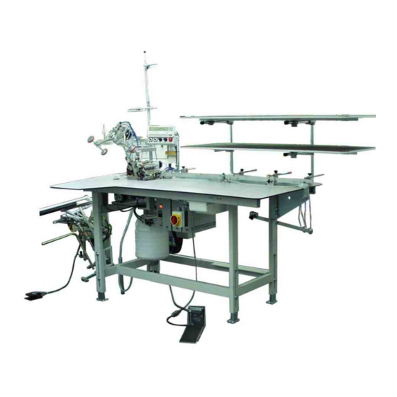
1281/5
Sewing unit for clo sing se ams
for trou sers and skirts
1
Operating instructions
2
Installation instructions
3
Service instructions
Frohn rad stra ße 10, D-63768 Hös bach
Telefon Ser vice +49 (0) 60 21/ 50 19 40 Ÿ Telefax +49 (0) 60 21/ 54 00 61 Ÿ E-mail: Vertrieb@beisler-gmbh.de
Aus ga be / Edi ti on:
06/2005
Prin ted in Fe de ral Re pub lic of Ger ma ny
Tei le-Nr.:/Part-No.:
Advertisement
Chapters
Table of Contents

Related Manuals for Beisler 1281/5


Summary of Contents for Beisler 1281/5
-
Page 1: Operating Instructions
1281/5 Sewing unit for clo sing se ams for trou sers and skirts Operating instructions Installation instructions Service instructions Frohn rad stra ße 10, D-63768 Hös bach Telefon Ser vice +49 (0) 60 21/ 50 19 40 Ÿ Telefax +49 (0) 60 21/ 54 00 61 Ÿ E-mail: Vertrieb@beisler-gmbh.de Aus ga be / Edi ti on: 06/2005 Prin ted in Fe de ral Re pub lic of Ger ma ny... - Page 3 Foreword This instruction manual is intended to help the user to become familiar with the machine and take advantage of its application possibilities in accordance with the recommendations. The instruction manual contains important information on how to operate the machine securely, properly and economically. Observation of the instructions eliminates danger, reduces costs for repair and down-times, and increases the reliability and life of the machine.
-
Page 4: General Safety Instructions
General safety instructions The non-observance of the following safety instructions can cause bodily injuries or damages to the machine. 1. The machine must only be commissioned in full knowledge of the instruction book and operated by persons with appropriate training. 2. -
Page 5: Table Of Contents
Index Page: Preface and general safety instructions Part 1: Operating instructions cl. 1281/5 Description of product Description of proper use ......... Brief description . - Page 6 Index Page: Error messages ..........USB stick General notes .
-
Page 7: Description Of Product
Description of product 1.1 Description of proper use The 1281/5 is a sewing unit which can properly be used for sewing light to medium-weight material. Such material is, as a rule, made of textile fibres. These materials are used in the garment industry. In general only dry material must be sewn on this machine. -
Page 8: Technical Data
– External control panel Efka V850 with: Menu navigation Freely programmable parameters for “Differential bottom feed (optional)”, “Needle feed (optional)”, “Ejector roller”, “Puller”, “Machine parameters”, “Global parameters”, “Program sequences” Input and output tests Check routine for step motors 20 program storage locations up to 7 seam programs per program storage location –... -
Page 9: Optional Equipment
Dimensions: 2300 x 1300 x 1500 mm (L x W x H) Working height: 850...1200 mm (upper table top edge) Weight: 125 kg Noise level: LC = 81dB (A) Workstation-specific emission value according to DIN 45635-48-B-1 Stitch length: 2.6 mm Seam length: 1000 mm Speed:... -
Page 10: Switching On - Switching Off - Program Stop
Switching on - Switching off - Program stop 3.1 Switching on – Switch on main switch 1 (turn in clockwise direction). The control loads the machine program. The basic display appears in the display of the control panel. 3.2 Switching off –... -
Page 11: Program Stop
3.3 Program stop For an immediate stop in case of operating errors, needle breakage etc. the safety system of the 1281/5 provides the following measures: – Press program stop switch 2 at the control panel. The running operations are stopped immediately. –... -
Page 12: Operation Of The Sewing Machine Head
Operation of the sewing machine head 4.1 General notes The operation of the sewing machine head (needle insertion, threading of needle thread and hook thread etc.) is described in the attached separate Pegasus operating instructions. The instruction manual is included in the accessories of the sewing unit. -
Page 13: Recommended Threads
Recommended threads Needle system: Recommended needle size: Nm 80 for very thin material Nm 90 for thin material Nm 100 for medium-weight material High sewing security and good sewability are achieved with the following core threads: – Two-ply polyester endless polyester core-spun (e.g. -
Page 14: Removing/ Putting On The Fabric Sliding Sheet
4.3 Removing / Putting on the fabric sliding sheet The fabric sliding sheet 2 is held in the gap of the table top by the magnets 1. The edge guide 3 is fastened on the fabric sliding sheet. Removing the fabric sliding sheet –... -
Page 15: Operation Of The Sewing Unit
Operation of the sewing unit 5.1 Preparation table and worktable The sewing unit is equipped with two preparation tables 1 and 2. The skirt parts or trousers parts are positioned on them. On the worktable 4 the trousers parts or skirt parts are fed and clamped with the mouse 3. -
Page 16: Mouse With Guide Rail And Return Mechanism
5.2 Mouse with guide rail and return mechanism The mouse is used for clamping the trousers and skirt parts to avoid their sliding away. The guide rail 3 is flexible and adaptable to the contour of the workpiece. Caution: Risk of injury ! Do not reach into the open mouse. - Page 17 Aligning the guide rail 3 – Place the workpiece 8 on the worktable opposite to the sewing direction. – Loosen toggle screws 9. – Place the guide rail 3 close to the contour of the workpiece. – Tighten toggle screws 9 again. Opening the mouse manually –...
-
Page 18: Feeding The Workpieces And Starting The Sewing Process
5.3 Feeding the workpieces and starting the sewing process The sewing unit for closing seams 1281/5 works semi-automatically at high speed. The operator of the sewing unit has to do the following: ® call up the desired seam program; ® feed and align the workpiece precisely;... -
Page 19: Adjusting The Blowing Air For The Nozzles In The Table Top
5.4 Adjusting the blowing air for the nozzles in the table top The blowing nozzles 1 in the table top support the precise stacking of the workpieces. – Set the intensity of the air blast by dial 2 at the control panel. Turn the dial to the right = increase the intensity of air blast Turn the dial to the left = reduce the intensity of air blast... -
Page 20: Setting The Return Speed Of The Mouse
5.5 Setting the return speed of the mouse The cylinder 2 presses the mouse mechanics 1 down. Thus, the mouse is pulled back to the feeding position. The return speed can be set. – Set the speed by dial 3 at the control panel. Turn dial to the right = higher speed Turn dial to the left... -
Page 21: Adjusting The Fullness Of Needle And Bottom Feed
5.6 Adjusting the fullness of needle and bottom feed Operator terminal in case of fullness adjustment Operator terminal in case of fullness adjustment via step motors via cylinder (optional equipment) Needle feed, bottom feed and puller feed can be adapted to the sewing conditions with the dials 1 and 2. -
Page 22: Setting The Pressure Of The Puller
5.7 Setting the pressure of the puller The pressure of the puller rollers 1 can be influenced via turning knob 2. – Turn knob 2 to the right. The pressure is increased. – Turn knob 2 to the left. The pressure is reduced. -
Page 23: Stacker
5.8 Stacker The finished workpieces are stacked on the throw-over stacker 2. The stacked and clamped workpieces can be removed by actuating the foot switch 1. The stacker is accessed by a control pulse. The pneumatic functions can be taken from the pneumatic wiring diagram. Caution: Risk of injury! Do not reach into the working area of the throw-over stacker during the stacking operation. -
Page 24: Operation Of The Control
Operation of the control 6.1 Operator terminal For the input and output of data an operator terminal with an LCD display and function keys is used. Display Enter keys Keys 1 - 0 Function keys Potentiometer Program stop Key Function —... - Page 25 Function Program the sequence (S) Creation of programs (Prg) Setting the global parameters Enter key Select parameter / scroll Alter parameter values...
-
Page 26: User Interface
User interface 6.2.1 Menu structure of the sewing and setting programs Switch on main switch Main screen Call up sewing programs Menu selection sewing stop Mouse back Manual within the to basic stacking seam position Key 1 Set needle feed via potentiometer Key 2 Set bottom feed via potentiometer Key 3 Set puller feed via potentiometer Key 4 Adjust the puller... - Page 27 Key 8 Input- Output test Key 9 Set global parameters Key 0 Creation of programs / Creation of sequences Calling up sewing programs – Switch the main switch on. The control initializes. The seam program previously used is loaded. – Press one of the keys “1, 2, 3, 4, 5, 6, 7, 8, 9, 0”.
-
Page 28: Seam Program
6.3 Seam programs Designation of the individual seams: 4 = Crotch seam of hind trousers on top/ lining down 6 = Crotch seam of hind trousers down/ lining on top 5 = Side seam of hind trousers down/ lining on top 7 = Side seam of hind trousers on top/ lining down A seam program in the display of the control panel Program No. - Page 29 The sewing unit 1281/5 is delivered with 9 standard seam programs: Program Seam Operation Position of Notes trousers Close crotch seam Hind trousers on top Automatical sewing with Lining down contour guide Close crotch seam Hind trousers down Automatical sewing with Lining on top contour guide Close crotch seam...
-
Page 30: Adjusting The Control
6.4 Adjusting the control The parameter values are altered in the individual parameter menus. – Press key “P”. – Select the menu item. – Select the parameter to be altered with the keys “F1” or “F2”. – Press key “E”. –... -
Page 31: Altering Seam-Specific Parameters
6.4.1 Altering seam-specific parameters Needle feed (with cylinder) Via this parameter the needle feed is set. Parameter 01: Line 1 Number of stitches until the needle feed engages Setting range: 0 - 2000 Parameter 02: Fullness line 1 ON/ OFF Setting range: 0 / 1 Parameter 03:... - Page 32 Bottom feed (with cylinder) Via this parameter the differential feed is set. Parameter 07: Line 1 Number of stitches until the differential bottom feed engages Setting range: 0 - 2000 Parameter 08: Fullness line 1 ON/ OFF Setting range: 0 / 1 Parameter 09: Line 2 Number of stitches how long the differential bottom...
- Page 33 Setting the ejector roller Via this parameter the ejector roller is set. Parameter 16: Number of stitches how long the seam chain is sucked (seam beginning) Setting range: 0..120 Parameter 17: Switch the stacker on or off Setting range: 0 / 1 Parameter 20: Number of stitches when the ejector roller lowers Setting range:...
- Page 34 Altering the machine parameters Parameter 30: Set the main speed Setting range: 0 - 6500 Parameter 31: Manual sewing on/ off Setting range: 0 / 1 Parameter 32: Number of stitches how long the table blowing remains switched on Setting range: 0 …400 stitches Parameter 33: Number of stitches until the automatic start engages...
- Page 35 Altering the potentiometer Parameter 18: Needle feed potentiometer Off / On Setting range: 0 / 1 Parameter 19: Differential feed potentiometer Off / On Setting range: 0 / 1 Parameter 24: Line 1, Needle feed potentiometer Off / On Setting range: 0 / 1 Parameter 25: Line 2,...
- Page 36 Setting the seam line Parameter 81: Length of line 1 Setting range: 0 ... Parameter 82: Line 1 Reduced speed Off / On Setting range: 0 / 1 Parameter 83: Line 1 Reduced speed Setting range: 500...6500 Parameter 84: Line 1 Stop at the end of the line Off / On Setting range: 0 / 1...
-
Page 37: Altering Global Parameters
6.4.2 Altering global parameters Parameter 29: Needle feed Maximum run Input: 0 …120 Parameter 38: Start delay light barrier Input: 0 …2000 Parameter 39: Differential feed Maximum run Input: 0 …120 Parameter 40: Basic value needle feed Input: 0 …120 Parameter 41: Basic value needle feed on / off Input:... -
Page 38: Input - Output Test
Altering global parameters Parameter 58: Display of the software version Parameter 59: Number of stitches how long the seam chain is sucked (seam beginning) Input: 0 …50 Parameter 65: Thread tension lift Input: 0 …50 Parameter 79: Soft start after “Stop in the seam” Input: 0 …500 6.4.3... - Page 39 Output test – Press key “P”. – Press key “8”. – Press key “Plus”. – Select the output element to be tested with the keys “Plus” or “Minus”. – Switch the output on or off with the key “F2”. – Press key “Program stop”.
-
Page 40: Creation Of Seam Programs
6.4.4 Creation of seam programs Note Before a new seam program can be created or an existing one can be deleted, the global parameter “56” has to be set to the value “0”. This avoids that the existing programs are changed inadvertently. –... -
Page 41: Deleting A Seam Program
6.4.5 Deleting a seam program – Press key “P” – Press key “9” – Press key “F2”. The display indicates: DELETE? – Press key “F2” anew. The program is deleted. – Press key “P”. You return to the selection menu. 6.4.6 Altering seam programs (Changing / Completing the sequence) Note... -
Page 42: Error Messages
Error messages In case of an error in the control system or in the machine program corresponding error messages are indicated in the display. Display Meaning Error 1 One of the parameters “18” or “19” is switched on (value = 1) Error 2 Both parameters “18”... -
Page 43: Usb Stick
USB stick 8.1 General notes The USB stick 1 serves for storing and transferring of the sewing unit software. By means of the USB stick program and parameter data can also be transferred to other sewing units. Commercially available USB 1 sticks can be used, too. 8.2 Formatting the USB stick Before using a new USB stick this has to be formatted correspondingly. -
Page 44: Usb Functions
8.4 USB functions The following functions can be carried out with a USB stick: 1) Storing and loading of global parameters File extension = *. PAR Parameter Function F-510 Securing from the control on the USB stick F-511 Loading from the USB stick in the control F-512 Comparing USB stick and control data F-513... - Page 45 If different program or parameter files are stored, the control allocates a new name each. Example: Storing of different parameter data 1st file 0100DATA.PAR 2nd file 0101DATA.PAR etc. The files can individually be renamed by the file manager or explorer on a PC.
-
Page 46: Storing Data On The Usb Stick
8.4.1 Storing data on the USB stick – Enter parameter. Example: 510 – Press key “E” The cursor flashes. – Press key “F2”. The file name chosen by the control appears. Example 0100DATA.PAR – Press key “E”. The data are written on the USB stick. Note The file name is allocated automatically. -
Page 47: Data Comparison
8.4.3 Data comparison – Enter parameter. Example: 512 – Press key “E”. The file name chosen by the control appears. Example 0100DATA.PAR – Press key “E”. The message appears. READ DATA YES = E – Press key “E” within 2 seconds. The data of the USB stick and the control are compared. -
Page 48: Loading Software Version From The Usb Stick
8.4.5 Loading software version from the USB stick – Enter parameter 523. – Press key “E”. The cursor flashes. – Press key “F2”. The name of the first file stored on the stick appears. Example 20_5D_1A.PRG – Select the desired parameter file with the keys “+” or “-”. –... -
Page 49: Removing The Usb Stick
8.5 Removing the USB stick – Switch the main switch off. – Pull the USB stick 1 out of the slot of the Efka control. -
Page 50: Maintenance
Maintenance 9.1 Cleaning and checking Caution: Risk of injury ! Switch the main switch off. The maintenance of the engineered sewing station must only be carried out with the machine switched off. Maintenance work has to be done after the intervals indicated in the tables at the latest (see column “Operating hours”). - Page 51 Maintenance work Explanation Operating to be done hours Machine head Clean the entire area 1 of the thread guides - Remove sewing dust and thread under the fabric sliding sheet remainders. (e.g. with compressed air pistol) Suction device Empty container 2 of the suction device Turn the bottom part of the container to the left and remove it...
-
Page 52: Oil Lubrication
9.2 Oil lubrication Caution: Risk of injury ! Oil may cause skin eruption. Avoid a longer contact with the skin. Wash yourself thoroughly after a contact. ATTENTION ! The handling and disposal of mineral oils is subject to legal regulations. Deliver used oil to an authorized collecting station. - Page 53 In dex Page: Part 2: Assembly in structions cl. 1281/5 Sco pe of de li very..........Ge ne ral no tes .
-
Page 55: Sco Pe Of De Li Very
Sco pe of de li very The scope of delivery depends on your order. The sewing unit consists of: – 1 Sewing machine head (as per order) – 2 Thread reel holder – 3 Control with control panel – 4 Material rests –... -
Page 56: In Stal Ling The Se Wing Unit
In stal ling the se wing unit 3.1 Trans port pro tec tions Before the installation of the sewing unit all transport protections have to be removed. – Remove the security tapes at the thread reel holder, machine table etc. –... -
Page 57: Setting The Working Height
3.2 Setting the working height The working height is adjustable between 850 and 1200 mm (measured up to the top edge of the table top). – Loosen screws 1 at the spars. – Set the desired working height with the help of suitable auxiliary means. -
Page 58: Mounting The Thread Reel Hol Der
3.3 Mounting the thre ad reel hol der – Insert thread reel holder 1 in retainer 2. – Tighten the thread reel holder with the two screws 3. 3.4 Moun ting the ma te ri al rests The material rests have be demounted for transportation. –... -
Page 59: Elec Tri Cal Con Nec Ti On
Elec tri cal con nec ti on ATTENTION ! Any work on the electrical equipment of the sewing unit must only be carried out by electricians or correspondingly instructed persons. The mains plug must be pulled out. 4.1 Che cking the no mi nal vol ta ge ATTENTION ! The nominal voltage indicated on the type plate of the sewing machine control and the mains voltage must correspond. -
Page 60: Pneu Ma Tic Con Nec Ti On
Pneu ma tic con nec ti on For the operation of the pneumatic components the sewing unit has to be provided with anhydrous compressed air. ATTENTION! For a trouble-free function of the pneumatic control processes the compressed air net has to be rated as follows: Even in the moment of maximum air consumption the minimum operating pressure must not drop below 6 bar. -
Page 61: Put Ting Into Ope Ra Ti On
Put ting into ope ra ti on 6.1 Se wing test After completion of the installation work a sewing test should be made. – Plug in the mains plug. Caution: Risk of injury! Switch the main switch off. Thread in needle and hook thread only with the sewing unit switched off. - Page 62 Für Ihre No tizen:...
- Page 63 Index Page: Part 3: Service instructions class 1281/5 General notes ..........Brief instructions for the sewing head Adjusting the height of the needle bar .
-
Page 65: General Notes
General notes The service instructions on hand describe the adjustment of the single-head overlock unit 1281/5. The manual consists of: · Brief instructions for the sewing head · Service instructions for the sewing unit ATTENTION ! The brief instructions are a summary of the detailed operating instructions of the sewing head. -
Page 66: Brief Instructions For The Sewing Head
Brief instructions for the sewing head 2.1 Adjusting the height of the needle bar Caution: Risk of injury! Switch the main switch off. Check and adjust the height of the needle bar only with the sewing unit switched off. Standard checking In the top dead centre of the needle bar the distance between the needlepoint 4 and the throat plate should amount to 9.7 - 9.9 mm. -
Page 67: Adjusting The Hook
2.2 Adjusting the hook 2.2.1 Distance between left hook and needle 2,3 - 2,5 mm Caution: Risk of injury! Switch the main switch off. Check and adjust the hook only with the sewing unit switched off. Cross-line adjustment Standard checking In the left reverse point of hook 5 the distance between the middle of the needle and the hook tip should amount to 2.3 - 2.5 mm. - Page 68 2,3 - 2,5 mm 0 - 0,05 mm Adjustment in sewing direction Standard checking The distance between hook tip 6 and needle 7 should amount to 0.0 - 0.05 mm. – Turn handwheel in direction of rotation until the hook tip is exactly at the level of the middle of the needle.
-
Page 69: Distance Between Right Hook And Needlel
2.2.2 Distance between right hook and needle Caution: Risk of injury! Switch the main switch off. Check and adjust the hook only with the sewing unit switched off. Cross-line adjustment Standard checking When the right hook is in its top reverse point, the distance between hook tip 9 and the middle of the needle should amount to 4.3 - 4.5 mm. - Page 70 Adjustment in sewing direction Standard checking When the right hook crosses the left hook, the distance “A” should amount to 0.5 mm and the distance “B” to 0.2 mm. Correction – Turn handwheel in direction of rotation until the right hook crosses the left hook.
-
Page 71: Adjusting The Needle Protection
2.3 Adjusting the needle protection 2.3.1 Hind needle protection Caution: Risk of injury! Switch the main switch off. Check and adjust the needle protection only with the sewing unit switched off. Standard checking When the tip of the left hook 3 is at the level of the middle of the needle, the needle protection 1 should abut on the needle. -
Page 72: Front Needle Protection
2.3.2 Front needle protection Caution: Risk of injury! Switch the main switch off. Check and adjust the needle protection only with the sewing unit switched off. Standard checking In the lower dead centre of the needle the distance between needle protection 1 and needle should amount to 0.03 - 0.05 mm. -
Page 73: Adjusting The Feed-Dog
2.4 Adjusting the feed-dog 2.4.1 Feed-dog position Caution: Risk of injury! Switch the main switch off. Check and adjust the feed-dog position only with the sewing unit switched off. Standard checking In their highest position the feed-dogs should be horizontal. –... -
Page 74: Feed-Dog Height
2.4.2 Feed-dog height Caution: Risk of injury! Switch the main switch off. Check and adjust the feed-dog height only with the sewing unit switched off. Standard checking When the feed-dogs are in their highest position, the teeth of the main feed-dog 4 should be 0.8 mm above the top edge of the throat plate, the teeth of the differential feed-dog 5 0.9 to 1.0 mm and the teeth of the auxiliary feed-dog 6 0.6 to 0.7 mm. -
Page 75: Presser Foot
2.5 Presser foot 2.5.1 Presser foot lift Head EXT 3216 Caution: Risk of injury! Switch the main switch off. Check and adjust the presser foot lift only with the sewing unit switched off. Standard When the piston rod 7 is extended, the lever 6 should abut on screw 5 and the clearance under the sewing feet should amount to 4 mm. -
Page 76: Presser Foot
2.5.2 Presser foot Caution: Risk of injury! Switch the main switch off. Check and adjust the presser foot only with the sewing unit switched off. Standard The hinges of the hinged sewing foot must be free of clearance and smooth-running. The front sewing foot sole 1 and the hind sewing foot soles 4 have to be in parallel position. -
Page 77: Upper And Lower Knife
2.6 Upper and lower knife 2.6.1 Changing and adjusting the upper knife Head EXT 32-16-03/233K Caution: Risk of injury! Switch the main switch off. Change and adjust the upper knife only with the sewing unit switched off. Standard In the lowest position of the upper knife the front edge of the blade should be 0.5 to 1.0 mm underneath the top edge of the throat plate. -
Page 78: Changing And Adjusting The Lower Knife
2.6.2 Changing and adjusting the lower knife Head EXT 3216-03/233K Caution: Risk of injury! Switch the main switch off. Change and adjust the lower knife only with the sewing unit switched off. Standard The blade of the lower knife has to be flush with the top edge of the throat plate. -
Page 79: Thread Regulation Overlock Hook
2.7 Thread regulation of overlock hook Caution: Risk of injury! Switch the main switch off. Check and adjust the thread regulation only with the sewing station switched off. Standard The position of the individual thread guides or thread pullers is dependent on the material, the sewing thread and the stitch type. -
Page 80: Adjusting The Sewing Unit
Adjusting the sewing unit 3.1 Adjusting the light barrier Caution: Risk of injury! The adjustment of the light barrier is done with the sewing unit switched on. Carry out adjustment and function test with utmost caution. Aligning the light barrier The light barrier 2 has to be aligned to the area 1 of the machine head. -
Page 81: Adjusting The Material Stop
3.2 Adjusting the material stop Caution: Risk of injury! Switch the main switch off. Adjust the material stop only with the sewing unit switched off. Standard The material stop 2 must completely abut on the sewing foot 3 so that the material cannot be pushed upward between sewing foot 3 and stop 2. -
Page 82: Adjusting The Contour Guide
3.3 Adjusting the contour guide Caution: Risk of injury! Switch the main switch off. Adjust the contour guide only with the sewing unit switched off. Standard The contour guide 1 should move forward as far as to ensure that both material plies 2 are always guided safely when sewing the contour. -
Page 83: Direct Sewing Drive
3.4 Direct sewing drive 3.4.1 Setting the reference Caution: Risk of injury! Switch the main switch off. Check and adjust the hook setting only with the sewing unit switched off. Standard When the needle is in the position “7 mm after the bottom dead centre”, the drive belt has to be put on in such a way that the feather key 2 in the motor shaft points to the marking 1 in the motor casing. -
Page 84: Oil Lubrication
Oil lubrication Caution: Risk of injury ! Oil can cause skin eruption. Avoid a longer contact with the skin. Wash yourself thoroughly after a contact. ATTENTION ! The handling and disposal of mineral oils is subject to legal regulations. Deliver used oil to an authorized collecting station. Conserve your environment. -
Page 85: Maintenance
Maintenance Caution: Risk of injury ! Switch the main switch off. The maintenance of the sewing unit must only be done with the machine switched off. The daily or weekly maintenance work (cleaning and oiling) to be carried out by the operators of the sewing unit is described in the operating instructions (chapter 8). - Page 86 Note:...
Need help?
Do you have a question about the 1281/5 and is the answer not in the manual?
Questions and answers