Casablanca Bel Air Instructions Manual
Hide thumbs
Also See for Bel Air:
- Owner's manual (20 pages) ,
- Owner's manual (20 pages) ,
- Owner's manual (16 pages)
Table of Contents
Advertisement
Quick Links
INTRODUCTION
MOUNTING RECOMMENDATIONS
FAN INSTALLATION
CONTROL FEATURES:
INTELI•TOUCH 3 OPERATION
INTELI•TOUCH 3 TROUBLESHOOTING
Safety and the proper operation of your Casablanca fan both require a thorough knowledge of the product and
proper installation; therefore, before attempting to install and operate your Casablanca fan, read this owner's
manual completely and carefully. Retain this manual for future reference.
CAUTION: To avoid possible electrical shock, make certain that electricity is turned off at the
circuit breaker or fuse box before attempting any installation procedure.
• CAUTION: RISK OF ELECTRICAL SHOCK! All wiring must be performed in accordance with national and local electrical codes. If
you are unfamiliar with the wiring codes, you should use a qualified electrician. To avoid overheating and possible damage to other
equipment, do not install control to a receptacle, fluorescent light fixture, motor operated appliance, or transformer-supplied appli-
ance..
• This fan is designed to be installed on an existing electrical outlet box. The outlet box must be UL Listed for ceiling fan installations, if
it is not, a new box must be installed. Casablanca extension poles are available for sloped or high ceiling installations.
• This ceiling fan requires a grounded electrical supply of 120 V AC, 60 Hz and a minimum 15 amp circuit. The maximum current require-
ment for the fan with light fixture is 3.8 amps. The fan uses about 1 amp or 100 watts. Maximum light current is 1.0 amps or 100 watts
of lighting.
• Where wire nuts are employed, be sure all bare wires are within the connectors. When installing the canopy hatch, make sure all wires
are within the canopy and that no wires are being pinched.
For best performance and for your warranty to be valid, use only genuine
• The blades in each pack are matched for equal
weight to assure smooth fan operation. If more
than one fan is being installed, be careful not to
mix blades from different cartons.
• Inspect the contents of your carton for possible
shipping or handling damage and report any such
damage directly to your authorized Casablanca
dealer.
• It is always a good idea to have an assistant to help
with the installation.
• When cleaning, painting, or working near your fan,
be very careful of the fan and blades. Always turn
the power OFF to the ceiling fan before servicing
it, working on it, or replacing light bulbs.
• Never insert anything into the path of the fan blades
while the fan is in operation.
• Never install a fan over a pool or spa.
• Never operate a fan that has been damaged in any
way. Contact Casablanca Fan Company by calling
1-888-227-2178, or contact your local authorized
Casablanca dealer for assistance in obtaining
service.
CONTENTS
READ AND SAVE THESE INSTRUCTIONS
SAFETY FIRST
BEFORE YOU START
Casablanca blades, light fixtures, and accessories.
SAFE USE
PN 3843Z
FUSE BOX
(remove fuse for The
circuiT you will be
working on)
CIRCUIT BREAKER
(Trip breaker for The
circuiT you will be
working on)
HN0909
18"
70"
84"
1
1
2
3
8
16
Advertisement
Table of Contents

Related Manuals for Casablanca Bel Air


Summary of Contents for Casablanca Bel Air
-
Page 1: Safety First
CONTENTS INTRODUCTION MOUNTING RECOMMENDATIONS FAN INSTALLATION CONTROL FEATURES: INTELI•TOUCH 3 OPERATION INTELI•TOUCH 3 TROUBLESHOOTING READ AND SAVE THESE INSTRUCTIONS SAFETY FIRST Safety and the proper operation of your Casablanca fan both require a thorough knowledge of the product and proper installation; therefore, before attempting to install and operate your Casablanca fan, read this owner’s manual completely and carefully. Retain this manual for future reference. CAUTION: To avoid possible electrical shock, make certain that electricity is turned off at the circuit breaker or fuse box before attempting any installation procedure. BEFORE YOU START • CAUTION: RISK OF ELECTRICAL SHOCK! All wiring must be performed in accordance with national and local electrical codes. If you are unfamiliar with the wiring codes, you should use a qualified electrician. To avoid overheating and possible damage to other equipment, do not install control to a receptacle, fluorescent light fixture, motor operated appliance, or transformer-supplied appli- ance.. • This fan is designed to be installed on an existing electrical outlet box. The outlet box must be UL Listed for ceiling fan installations, if it is not, a new box must be installed. Casablanca extension poles are available for sloped or high ceiling installations. • This ceiling fan requires a grounded electrical supply of 120 V AC, 60 Hz and a minimum 15 amp circuit. The maximum current require- ment for the fan with light fixture is 3.8 amps. The fan uses about 1 amp or 100 watts. Maximum light current is 1.0 amps or 100 watts of lighting. -
Page 2: Mounting Recommendations
MOUNTING RECOMMENDATIONS Before mounting your Casablanca fan, read the following helpful recommendations. The location of the fan, air circulation, and fan size are all important factors to consider before installation. Location Ceiling fans have practical uses in almost every room in your home. We suggest you follow these mounting recom- mendations as you decide where to install your Casablanca fan. • For safety reasons, the fan blades must be a minimum of 7” above the floor. • Do not locate the fan in a doorway or above a swinging door. • In any installation, the tips of the blades must be at least 18” from the wall in order to provide sufficient clearance for the blades. • In bedrooms, fans work best when mounted above the foot of the bed. -
Page 3: Installing Instructions
® INSTALLING INSTRUCTIONS Unpacking: Before assembling and installing your ceiling fan, remove all parts from the shipping cartons and check them against the parts listed here. Before discarding packaging material, be certain that all parts have been removed. iMPortaNt! To avoid possible damage to the Halogen bulb holder the fan must be placed on the styrofoam packaging from the box. -
Page 4: Canopy Installation
CROSSBAR MOUNTIING BRACKET INSTALLATION Proceed with installation as follows: CEILING Step 1. Route the wires from the ceiling outlet box through the crossbar mounting bracket center hole. Attach the APPROVED bracket, with ground wire and ridges down, to the ceiling OUTLET fixture outlet box with the mounting hardware included with RIDGE... - Page 5 ® INSTALLING THE FAN BODy TOP COVER iMPortaNt! To avoid possible damage to the Halogen bulb holder the fan must be placed on the styrofoam packaging from the box. After removing the top cover from the upper half of the TOP COVER styrofoam, take the packaging from the box and RETAINING...
-
Page 6: Hanging The Fan
HANGING THE FAN Step 7. To hang the fan body in the canopy, hold the fan body firmly and insert the ball into the canopy opening. Check that no wires were pinched. Rotate the fan body until the slot in the ball fits into the BALL pin opposite the canopy opening. -
Page 7: Installing The Glass Shade
® BLADE HOLDER HARDWARE BLADE SCREW (4 FLAT WASHER PER BLADE) (4 PER BLADE) CENTER STYLE BLADE HOLDER & BLADE BLADE SCREW Step 12. blade Installation (4 PER BLADE) Attach the blades to the blade holders with four blade FLAT WASHER screws and four steel washers (4 PER BLADE) provided for each blade. Hand tighten securely. INSTALLING THE HALOGEN BULB Step 13. Screw the 100 Watt Halogen bulb into the socket. - Page 8 ® W-85 CONTROL INSTALLATION WALL CONTROL AND HARDWARE (not to scale) (4) Wire Cap Wall Plate W-85 Switch Bezels Switch Mounting Screws White Wall Almond Wall Wall Control (1) White Screws (2) (2) White Plate(1) Plate(1) (1) Almond (2) Almond WARNING! BEZEL To avoid possible electrical shock, make cer- tain that electricity is turned off at the circuit breaker or fuse box before attempting any in- stallation or repair procedure...
- Page 9 ® W-85 Wall Control Bezel replacement: - ALMOND CONTINUED BEZEL Step 17c. Reinstall the rubber key pad on to the four (4) locating pins located on the almond bezel as shown in Figure #3 and #4. RUBBER KEY Figure #3 RUBBER KEY Step 17d. To attach the bezel back on to the front of the switch you will need to align the four (4) tabs on the bezel with the front of the wall control and by gently pressing on both top and button of the bezel at the same time, snap the bezel back on to the front of the switch as shown in figure #5.
-
Page 10: Single W-85 Installation
® INSTALLING THE W-85 WALL CONTROL NOTE: W-85 Wall Control should only be installed on Casablanca's Inteli-Touch 3 fans with DOWNLIGHTS ONLY. ® The wall control installs in the same manner as an ordinary light switch, using an existing wall box and wiring. This controller is designed to signal the fan microcomputer as well as perform normal switching operations. -
Page 11: Dual W-85 Installation
® DUAL W-85 INSTALLATION DIP SWITCHES To control the fan and lights from two locations (a three-way circuit), use two W-85 wall controls as shown in the wiring diagram in Figure #5. Before installing the two switches into the wall, place both switches side by side, then locate the 4 dip switches on the side of the two switches. Then make sure that the dip switches are set to the same address on both switches as shown in Figure #4. When setting these dip switches you are setting the channel number that is required to control both your fan and lights from both sides of the room. - Page 12 ® OPERATION POWER button is normally left in the on position. Always turn the power off during cleaning or servicing the fan and during thunderstorms. It is also used to exit or enter ad- ditional programs. button must be left on to retain a previously set fan speed or light level. OPERATION SPEED CONTROL There are six individual speed settings for the fan;...
-
Page 13: Changing Frequency Setting
® CHANGING FREQUENCY SETTING NOTE: All fans leave the factory set to “1111” SWITCHES You will only have to change the dip switch settings in the remote if you are using more than one fan in the same area and want to control them separately. Step 1. Turn power OFF at the circuit breaker or fuse box and at the toggle switch, for the fan you want to change. -
Page 14: Operation Safe-Exit
® OPERATION SAFE-EXIT AND LIGHT -MINDER PROGRAM ® ® NOTE: Both Light-Minder and Safe-Exit programs will always run at the same time. The Safe-Exit Program gives you about thirty seconds of light when you turn the lights off, enabling you to exit your home before the lights go out. To enter the Safe-Exit Program: Safe-Exit 1) To operate the lights for Safe-Exit Program – Press the button off for at least five seconds. 2) Turn the Power on. Immediately press the buttons in the following sequence: . Immediately press the Button after an audio tone is heard from the fan controller. - Page 15 ® OPERATION FAN-MINDER PROGRAM ™ The Fan-Minder feature will add to your comfort when used in the bedroom. The program reduces the speed of the fan each two-hour interval to compensate for cooling night air. To enter the Fan-Minder Program: 1. Turn the OFF for at least 5 seconds. 2. Turn the 3. Immediately operate the buttons in the following sequence: 4. The fan will respond with three descending tones. A timer is now initiated and the fan will reduce one speed for each two-hour interval. The fan will not, however, descend below the second lowest speed. 5. You may increase the fan speed by pressing and holding the button until the desired speed is reached, then release it.
-
Page 16: Troubleshooting Tips
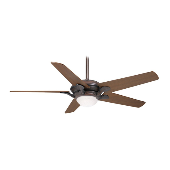
Connect the equipment into an outlet on a circuit different from that to which the receiver is connected. Consult the dealer or an experienced radio/TV technician for help. Note: Any changes or modifications to the transmitter or receiver not expressly approved by Casablanca Fan Company may void one’s authority to operate this remote control. - Page 17 PRODUCT SPECIFICATIONS ® Model Name: Bel Air Motor: XLP-2000 ® Model Number: 38xx Blade Span With: 55" Blade Pitch: 14° Dimensions: 8.6" No. of Blades: B = 13.9" Technology: Inteli•Touch ® 2.8" Lightbulbs: 100-watt halogen (1) D = 12.2" 5.6" Airflow: 7,174 cfm Weight: 24 lbs.
Need help?
Do you have a question about the Bel Air and is the answer not in the manual?
Questions and answers