Table of Contents
Advertisement
Quick Links
Advertisement
Table of Contents

Related Manuals for TYAN Transport GX28 B2881


Summary of Contents for TYAN Transport GX28 B2881
- Page 1 Transport GX28 B2881 User’s Manual Document part number: D1584-100...
- Page 2 TYAN retains the right to make changes to product descriptions and/or specifications at any time, without notice. In no event will TYAN be held liable for any direct or indirect, incidental or consequential damage, loss of use, loss of data or other malady resulting from errors or inaccura- cies of information contained in this document.
- Page 3 Federal Communications Commission Notice for the USA Compliance Information State- ment (Declaration of Conformity Procedure) DoC FCC Part 15: This device complies with part 15 of the FCC Rules. Operation is subject to the following conditions: 1) This device may not cause harmful interference, and 2) This device must accept any interference received including inter- ference that may cause undesired operation.
- Page 4 About this manual This manual provides you with instructions on installiing your Transport GX28 (B2881) consists of the following sections. Chapter 1 – Overview: Provides an introduction to the Transport GX28 (B2881) bourbons, shows a packing list, describes the external components, shows a tables of key components, and provides a block diagram of the sys- tem.
- Page 5 Safety information Before installing and using the Transport GX28, take note of the fol- lowing precautions: • Read all instructions carefully. • Do not place the unit on an unstable surface, cart, or stand. • Do not block the slots or openings on the unit which are provided for ventilation.
-
Page 6: Table Of Contents
Table of Contents Chapter 1: Overview 1.1 About the Transport GX28 (B2881) ..........1 1.2 Product models................1 1.3 Features ..................2 1.4 Unpacking ..................3 1.4.1 Box contents................3 1.4.2 Accessories ................4 1.4.3 Opening the box..............5 1.5 About the product................. - Page 7 3.8 Replacing the cooling fans ............51 3.8.1 Pin header diagram ..............52 Appendix BIOS....................53 Introduction..................53 BIOS setup utility ................53 BIOS menu bar ................55 BIOS legend bar................55 BIOS main menu ................56 BIOS advanced menu ..............57 IDE configuration submenu............
-
Page 8: Chapter 1: Overview
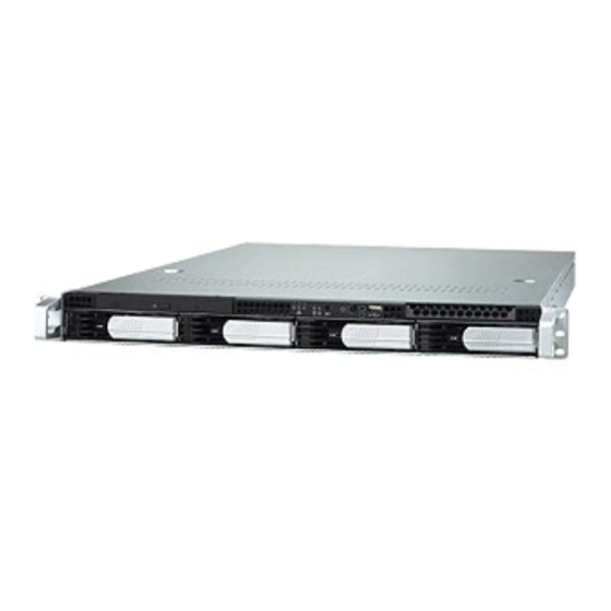
Chapter 1: Overview About the Transport GX28 (B2881) Congratulations on your purchase of the Transport GX28 (B2881), rack mountable, barebone system for the AMD Opteron processor. The GX28 uses AMD's revolutionary x86- 64 Opteron™ processor technology, offering exceptional computing power and simultaneous support of 32-bit and 64- bit applications. -
Page 9: Features
Slim 24x CD-ROM drive • Optional 3.5-inch FDD Processors Motherboard • Dual PGA 940-pin ZIF socket • Tyan Thunder K8S Pro S2881G2NR (B2881 G28S4H) or S2881UG2NR ® • Support for single or dual AMD (B2881 G28U4H) Opteron™ 200 series processors •... -
Page 10: Unpacking
Component Description Industry standard 1U chassis, (4) hot swappable HDD bays Choice of motherboard (pre-installed) • B2881 G28S4H - Tyan S2881G2NR • B2881 G28U4H - Tyan S2881UG2NR 24x slim CD-ROM drive (pre-installed) SATA or SCSI backplane and holding bracket (pre-installed) LED control board (pre-installed) (1) 1U, 64-bit riser card, 3.3V (pre-installed) -
Page 11: Accessories
K8S Pro AJS #D 1528 - 100 ID : 1540 - 100 Revision 1.0 Revision 1.0 Hardware User's Manual Installation Guide (1) Air duct Tyan K8S Pro S2881 motherboard user manual and Transport GX28 (B2881) hardware installation guide Chapter 1: Overview... -
Page 12: Opening The Box
1.4 Unpacking 1.4.3 Opening the box Open the box carefully and ensure that all components are present and undamaged. The product should arrive pack- aged as illustrated below. Packaged box contents Sliding rail kit Accessory pack Packaged accessories Contact your distributor if anything is missing or appears damaged. -
Page 13: About The Product
1.5 About the product About the product This section contains hardware diagrams and a block dia- gram of the GX28 system. 1.5.1 System front view and front panel. HDD activity LED Reset Power button LAN activity Power USB port 1.5.2 System rear view Power supply socket Stacked PS/2 mouse and keyboard ports USB ports... -
Page 14: System Internal Views
1.5 About the product 1.5.3 System internal views B2881 G28S4H USB board Power supply A/C connector Slim CD-ROM drive System fan, rear Front panel cables EPS 12V 400W power supply SMDC card holder System cooling fan assembly Memory sockets SATA backplane CPU sockets LED and switch board PCI-X slot... - Page 15 1.5 About the product B2881 G28U4H USB board System fan, rear Slim CD-ROM drive Power supply A/C connector Front panel cables EPS 12V 400W power supply Memory sockets System cooling fan assembly CPU sockets SCSI backplane PCI-X slot LED and switch board Motherboard power connectors Chapter 1: Overview...
-
Page 16: Block Diagram
1.5 About the product 1.5.4 Block diagram Thunder K8SR (S2881) block diagram DIMM2 DIMM4 DIMM2 DIMM4 Upper 64-bit Upper 64-bit 128-Bit Dual Channel CPU 1 CPU 2 128-Bit Dual Channel Lower 64-bit Lower 64-bit DIMM3 DIMM1 DIMM1 DIMM3 PCI-X Slot 2 PCI-X Slot 1 PCI-X BUS A Broadcom 5704C... - Page 17 Memo...
-
Page 18: Chapter 2: Setting Up
Chapter 2: Setting up Before you begin This chapter explains how to install motherboard components including CPUs, memory modules, and PCI-X cards. There are also instructions in this section for installing SATA and SCSI hard drives. Careful attention should be given to the precautions men- tioned in this section when setting up your system. -
Page 19: Precautions
2.1 Before you begin 2.1.3 Precautions Components and electronic circuit boards can be damaged by static electricity. Working on a system that is connected to a power supply can be extremely dangerous. Follow the guidelines below to avoid damage to the Transport GX28 or injury to yourself. -
Page 20: Installing Motherboard Components
2.2 Installing motherboard components Installing motherboard components This section describes how to install CPUs, memory mod- ules, and PCI-X cards. 2.2.1 Removing the chassis cover Follow these instructions to remove the GX28 chassis cover. This step is required before any other procedures in this chapter can be undertaken. -
Page 21: Installing Cpus
2.2 Installing motherboard components 2.2.2 Installing CPUs This section describes how to install AMD Opteron proces- sors and heatsinks in your GX28 system. This section applies to all models. 1. Remove the chassis cover as described in section 2.2.1 Removing the chassis cover. 2. - Page 22 2.2 Installing motherboard components 4. Lift the CPU locking lever as shown. 5. Place the CPU in the CPU socket, ensuring that pin 1 is located as shown. pin 1 Chapter 2: Setting up...
- Page 23 2.2 Installing motherboard components 6. Press the CPU locking lever down to secure the CPU in the socket. 7. Repeat steps four to six for the second CPU. 8. Apply thermal grease to the top of the CPUs and place the CPU heatsinks on the CPUs.
-
Page 24: Installing Memory
2.2 Installing motherboard components 2.2.3 Installing memory Follow the instructions in this section to install memory mod- ules in your GX28 system. 1. Remove the chassis cover as described in section 2.2.1 Removing the chassis cover. 2. Locate the memory slots on the motherboard. Memory slots 3. -
Page 25: Installing A Pci-X/Pci Card
2.2 Installing motherboard components 5. Insert the memory module into the slot as shown. The locking levers will snap into position 6. Ensure that the locking levers are firmly in place and that the memory module is properly seated in the slot. 2.2.4 Installing a PCI-X/PCI card Follow the instructions in this section to install a PCI-X or PCI card in your system using the supplied riser card. - Page 26 2.2 Installing motherboard components 3. Choose a slot in which to install a card and remove the screws securing the clamp as shown. 4. Loosen the clamp as shown. Note: There are two PCI-X/PCI card slots available and the retaining clamp is different for each one.
- Page 27 2.2 Installing motherboard components 6. Press the PCI-X/PCI card into place in the slot on the riser card. Ensure that the card is seated properly in the slot on the riser card and that the riser card is properly seated in its slot on the motherboard. 7.
-
Page 28: Installing A Hard Drive
2.3 Installing a hard drive Installing a hard drive The GX28 supports up to four SATA (S4H model) or SCSI (U4H model) hard drives. 2.3.1 Installing a SATA hard drive Note: This section applies only to the B2881G28S4H model. Follow these instructions to install an external SATA hard drive in your GX28 system. - Page 29 2.3 Installing a hard drive 3. Place a SATA drive in the drive tray. Note: If you are replacing an existing HDD, you will need to remove the four screws that secure it in the drive bay and remove it. 4.
-
Page 30: Installing A Scsi Hard Disk
2.3 Installing a hard drive 5. Reinsert the drive tray into the chassis. Ensure that the rear connector of the new drive is firmly seated in the backplane. Note: The GX28 is shipped with SATA or SCSI backplane and cables pre-installed. 2.3.2 Installing a SCSI hard disk Note: This section applies only to the... - Page 31 2.3 Installing a hard drive 2. Slide the drive bay out 3. Place a SCSI drive in the drive tray. Note: If you are replacing an existing HDD, you will need to remove the four screws that secure it in the drive bay and remove it. 4.
- Page 32 2.3 Installing a hard drive 5. Reinsert the drive tray into the chassis. Ensure that the rear connector of the new drive is firmly seated in the backplane. Note: The GX28 is shipped with SATA or SCSI backplane and cables pre-installed. SCSI drive rear view 80 pin SCA II type connector...
-
Page 33: Rack Mounting
2.4 Rack mounting Rack mounting Follow these instructions to mount the GX28 into an industry standard 19-inch rack. Note: Before mounting the Transport GX28 in a rack, ensure that all internal components have been installed and that the unit has been fully tested. Maintenance can be performed on the unit while in a rack but it is preferable to install the device in a fully operational condition. - Page 34 2.4 Rack mounting Note: Ensure that the brackets with the cut away section (to accommodate the handles on the front of the unit) are fixed to the front end of the rail. 3. Fully extend the sliding rails until they lock. Note: Do not tighten the brackets to the rails as you will need to adjust their position...
- Page 35 2.4 Rack mounting Note: When fully extended, the sliding rails will lock. The release mechanism is located on the sliding rail as shown. Press the release mechanism (A) while pushing the sliding rails (B) to shorten them. 6. With the rails in their shortest position, adjust both front mounting brackets so that they are flush with the front of the unit.
- Page 36 2.4 Rack mounting 9. Lift the unit into place in the rack and secure it into place as shown. Note: To avoid injury, it is strongly recom- mended that two people lift the GX28 into place while a third person install it in the rack.
- Page 37 Memo...
-
Page 38: Chapter 3: Replacing Pre-Installed Components
Chapter 3: Replacing pre-installed components Introduction This chapter describes how to replace all the pre-installed components of your GX28, including PCI-X cards, riser card, motherboard, CD-ROM drive, and LED control board. There is also a section covering the replacement of the 4-port SATA backplane and 4-port SCSI backplane. -
Page 39: Replacing Motherboard Components
3.2 Replacing motherboard components Replacing motherboard components This section contains instructions for removing motherboard components and the motherboard. 3.2.1 Disconnecting all motherboard cables When replacing the motherboard or certain motherboard components, it may be necessary to remove cables con- nected to the motherboard. Follow these instructions to remove all motherboard cabling. - Page 40 3.2 Replacing motherboard components 3. Disconnect SCSI cables if installed. 4. Disconnect the front panel LED connectors. Chapter 3: Replacing pre-installed components...
- Page 41 3.2 Replacing motherboard components 5. Disconnect the CD-ROM IDE cable. 6. Disconnect fan power supplies. Fan power supply pin headers are located at various points on your motherboard. See Pin header diagram on page 52. Chapter 3: Replacing pre-installed components...
-
Page 42: Removing Motherboard Components
3.2 Replacing motherboard components 3.2.2 Removing motherboard components Follow these instructions to remove the air duct, CPUs, PCI riser card, and memory modules. Air duct 1. Remove the two screws that secure the air duct. 2. Remove the air duct as shown. CPUs 1. - Page 43 3.2 Replacing motherboard components 3. Lift the CPU locking lever as shown. 4. Remove the CPU. PCI riser card 1. Remove any PCI-X cards from the riser card if they are installed. 2. Remove the PCI riser card as shown Chapter 3: Replacing pre-installed components...
-
Page 44: Replacing The Motherboard
3.2 Replacing motherboard components Memory modules 3. Push out the memory module locking levers as shown. 4. Remove the memory module. 3.2.3 Replacing the motherboard Follow these instructions to remove the motherboard from your GX28. Note: Before proceeding, you must remove all cable connections to the mother- board. - Page 45 3.2 Replacing motherboard components 4. Remove the single screw from the retaining clip for the PCI-X/PCI riser card and remove the clip. 5. Remove the ten screws securing the motherboard to the chassis. 6. Remove the motherboard from the chassis. Chapter 3: Replacing pre-installed components...
-
Page 46: Replacing The Slim Cd-Rom Drive
3.3 Replacing the slim CD-ROM drive Replacing the slim CD-ROM drive This section describes how to remove and replace the CD- ROM drive in your GX28 system. 1. Remove the chassis cover as described in section 2.2.1 Removing the chassis cover. 2. -
Page 47: Replacing The Led Control Board
3.4 Replacing the LED control board 5. Remove the CD-ROM drive backplane as shown. Replacing the LED control board Follow these instructions to replace the LED control board. 1. Remove the chassis cover. See Removing the chassis cover on page 13. 2. -
Page 48: Replacing The Front Panel Usb Board
3.5 Replacing the front panel USB board 3. Remove the three screws that secure the LED control panel to the chassis and lift the board free of the chassis. Replacing the front panel USB board Follow these instructions to replace the front panel USB board. -
Page 49: Replacing The Storage Backplane
3.6 Replacing the storage backplane Replacing the storage backplane This section describes how to replace the SATA or SCSI backplane on your GX28. 3.6.1 Replacing the SATA backplane. This section includes instructions for removing the SATA backplane and a features diagram. Follow these instructions to replace the SATA backplane on your GX28. - Page 50 3.6 Replacing the storage backplane 6. Remove the three screws that secure the SATA back- plane bracket to the chassis. 7. Lift the backplane bracket free of the chassis as shown. 8. Remove the six screws that secure each SATA back- plane to the chassis and remove them from the chassis.
- Page 51 3.6 Replacing the storage backplane 3.6.1.1 SATA backplane features JP1 LED output, J3 serial ATA 7 pin 2 x 6 pin header connector J4 HDD2 serial ATA 7 pin connector J5 DC input pow- er connector Chapter 3: Replacing pre-installed components...
- Page 52 3.6 Replacing the storage backplane 3.6.1.2 SATA backplane specifications • Supports serial ATA interface • Supports 2-bay serial ATA hard disk drive inrush current con- trol for hot-swapping • Supports serial ATA hard disk drive serial ATA interface plus serial ATA power (7+15 pin connectors. •...
-
Page 53: Replacing The Scsi Backplane
3.6 Replacing the storage backplane 3.6.2 Replacing the SCSI backplane This section includes instructions for removing the SCSI backplane and a features diagram. Follow these instructions to replace the SCSI backplane on your GX28. Note: This section applies only to the GX28 B2881 U4H. - Page 54 3.6 Replacing the storage backplane 4. Remove the metal retaining plate as shown. 5. Disconnect all cables from the SCSI backplane including two power cables and one SCSI data cable. 6. Remove the ten screws securing the SCSI backplane in place.
-
Page 55: Scsi Backplane Features
3.6 Replacing the storage backplane 3.6.2.1 SCSI backplane features J8 BIG 4P 90DEG J5 80 PIN SCA2 J7 BIG 4P 90DEG J10 SLIM FLOPPY F3 FAN 3P BZ1 BUZZER J4 80 PIN SCA2 U14 MPU F1/2 FAN 3P J6 FRONT PANEL DISPLAY J3 80 PIN SCA2... - Page 56 3.6 Replacing the storage backplane 3.6.2.2 SCSI backplane specifications • Supports SCSI interface, Ultra 320/160 with backward compatibility. • Supports 80-pin hard disk drive, SCA2 Ultra 320/160 with backward compatibility. • Supports SCSI-in connector (68-pin, female). • Supports 4 bay hard disk inrush current control for hot- swapping.
-
Page 57: Replacing The Power Supply
3.7 Replacing the power supply Replacing the power supply Follow these instructions to replace the power supply in your GX28 system. 1. Remove the chassis cover as described in section 2.2.1 Removing the chassis cover. 2. Disconnect the power cables from the motherboard. See Disconnecting all motherboard cables on page 32. -
Page 58: Replacing The Cooling Fans
3.8 Replacing the cooling fans Note: The power supply is grounded to the chassis and the chassis is connected to the grounding pin in the power supply cable. When replacing the power supply, it is essential that the green grounding wires from the power supply socket and the power supply are connected to the chassis. -
Page 59: Pin Header Diagram
3.8 Replacing the cooling fans 3.8.1 Pin header diagram Fan 1 Fan 2 Fan 3 Fan 4 Fan 5 Fan 6 Fan 9 Fan 8 Fan 7 Chapter 3: Replacing pre-installed components... -
Page 60: Appendix
BIOS Introduction Your Transport GX28 (B2881) system includes a powerful TYAN K8S Pro S2881 motherboard with AMI BIOS v8.0 on 4 Mb flash ROM. The BIOS is the motherboard’s basic input/output system. The BIOS contains all the settings required to control the key- board, display, disk drives, serial communications, and a number of miscellaneous functions. - Page 61 BIOS setup utility Main Advanced PCI/PnP Boot Security Chipset Power Exit System Overview Use [Enter], [TAB] or AMIBIOS [SHIFT_TAB] to select Version : 08.00.xx a field Build Date : 7/17/2003 : 0AAAA000 Use [+] or [-] to config- ure system time. Processor Type : AMD Opteron™...
-
Page 62: Bios Menu Bar
BIOS menu bar The menu bar at the top of the window lists the following selections: Menu bar selections Main To configure basic system setups Configure basic system settings Main Advanced Configure advanced chipset options PCI/PnP Configure legacy PnP or PCI settings Boot Configure system boot order Security... -
Page 63: Bios Main Menu
BIOS main menu The Main BIOS menu is the first screen that appears when you enter BIOS setup. The menu has two main frames. The left frame displays all the options that can be configured. “Grayed-out” options cannot be configured, options in blue can be changed. -
Page 64: Bios Advanced Menu
BIOS advanced menu Select any of the items in the left frame of the screen, such as Super I/O Configuration, to go to the submenu for that item. Display an Advanced BIOS Setup option by highlighting it using the <Arrow> keys. All Advanced BIOS Setup options are described in this section. -
Page 65: Ide Configuration Submenu
IDE configuration submenu Use this screen to change IDE configuration settings. Main Advanced PCI/PnP Boot Security Chipset Power Exit IDE Configuration Use [Enter], [TAB] Onboard PCI IDE Controller [Both] or [SHIFT_TAB] to select a field Primary IDE Master : [xxxx] Primary IDE Slave : [xxxx] Use [+] or [-] to... -
Page 66: Floppy Configuration Submenu
Feature Option Description Host Configures how the BIOS ATA(PI) Device detects whether an 80-pin IDE Host and Device cable is attached Host - Use chipset to detect Device - Use IDE device to detect Floppy configuration submenu Use this screen to change the floppy configuration settings. Main Advanced PCI/PnP Boot Security Chipset Power Exit Floppy Configuration Use [Enter], [TAB] or... -
Page 67: Super I/O Configuration Submenu
Features Option Description • Disabled This setting defines the type of Floppy B • 360 KB 5 1/4” floppy drive installed in the sys- • 1.2 MB 5 1/4” • 720 KB 3 1/2” • 1.44 MB 3 1/2” • 2.88 MB 3 1/2” Super I/O configuration submenu Use this screen to change the configuration of super I/O. -
Page 68: Hardware Health Event Monitoring Submenu
Feature Option Description Parallel Port • Bi-Direc- Configures parallel port mode Mode tional Bi-directional - send and receive data • Normal Normal - can send data • EPP EPP - enhanced parallel port Parallel Port • IRQ7 Assigns IRQ to parallel port Interrupt •... - Page 69 Feature Description Hardware Health Event Monitoring CPU1 Temperature Displays CPU, ambient and VRM temper- atures. CPU2 Temperature System Temperature CPU1 Fan Speed Displays speed of fans connected to appropriate fan headers. CPU2 Fan Speed FAN1 Speed FAN2 Speed FAN3 Speed FAN4 Speed CPU1 V_core Displays voltage information for CPUs,...
-
Page 70: Event Log Controls Submenu
Event log controls submenu Use this screen to view the event log control menu. This logs system events (such as CMOS clear, ECC memory errors, etc.) and writes the log into NVRAM. The settings are described on the following pages. Main Advanced PCI/PnP Boot Security Chipset Power Exit DMI Event Logging Use [Enter], [TAB] or... -
Page 71: Remote Access Configuration Submenu
Remote access configuration submenu Use this screen to view the remote access configuration menu. This feature allows remote access to the server using the serial port. Main Advanced PCI/PnP Boot Security Chipset Power Exit Configure Remote Access Type and Parameters Use [Enter], [TAB] or [SHIFT_TAB] to select Remote Access... -
Page 72: Usb Configuration Submenu
USB configuration submenu Use this screen to view the USB configuration menu. The set- tings are described on the following pages. Main Advanced PCI/PnP Boot Security Chipset Power Exit USB Configuration Use [Enter], [TAB] or [SHIFT_TAB] to select USB Function [Enabled]] a field Legacy USB Support... -
Page 73: Onboard Device Submenu
Onboard device submenu Use this screen to configure onboard devices and PCI slots. Integrated devices can be enabled or disabled using this menu. Main Advanced PCI/PnP Boot Security Chipset Power Exit Device and PCI Slots Configuration Use [Enter], [TAB] or [SHIFT_TAB] to select Onboard Serial ATA [Enabled]... -
Page 74: Bios Pci/Pnp Menu
BIOS PCI/PnP menu Use this screen to view PnP (Plug & Play) BIOS Configura- tion Menu. This menu allows the user to configure how the BIOS assigns resources & resolves conflicts. Main Advanced PCI/PnP Boot Security Chipset Power Exit Advanced PCI/PnP Settings Use [Enter], [TAB] or WARNING: Setting wrong values in below sec- [SHIFT_TAB] to select... - Page 75 Feature Option Description Advanced PCI/PnP Menu Plug & Play OS • Yes The Yes setting allows the operating • No system to change the interrupt, I/O, and DMA settings. Set this option to Yes only if the system is running Plug and Play aware operating sys- tems.
-
Page 76: Bios Boot Menu
BIOS boot menu Display the boot settings option by highlighting it using the <Arrow> keys and pressing <Enter>. Main Advanced PCI/PnP Boot Security Chipset Power Exit Boot Settings Use [Enter], [TAB] or [SHIFT_TAB] to select Boot Settings Configuration a field Boot Device Priority Use [+] or [-] to config- Removable Drives... - Page 77 Feature Option Description Boot Settings Configuration Quick Boot Mode • Enabled Enables user to bypass BIOS self • Disabled test during POST. Quiet Boot • Disabled Enable this option to hide BIOS • Enabled Post messages during POST Add On ROM •...
-
Page 78: Bios Security Menu
BIOS security menu The system can be configured so that all users must enter a password every time the system boots or when BIOS Setup is entered, using either the Supervisor password or User password. The Supervisor and User passwords activate two different levels of password security. -
Page 79: Bios Chipset Settings
Feature Option Description Clear User Select this option to clear User Password — Password Boot Protects the first sector of the Hard Drive Sector from being written — Virus Protection BIOS chipset settings This menu enables the user to customize functions of the AMD Chipset. -
Page 80: Northbridge Chipset Configuration Submenu
Northbridge chipset configuration submenu This menu gives options for the Northbridge chipset configu- ration settings. Main Advanced PCI/PnP Boot Security Chipset Power Exit Northbridge Bridge Chipset Configuration Use [Enter], [TAB] or [SHIFT_TAB] to select Memory Configuration a field ECC Configuration IOMMU Configuration Use [+] or [-] to config- PCI-X Configuration... -
Page 81: Ecc Configuration Submenu
Feature Option Description Memory configuration Bank Interleaving • Disabled Allows memory access to be spread • Enabled across memory banks. Node Interleaving • Disabled Allows memory access to be spread • Enabled across memory nodes. Burst length • 8 beats Burst length must be set to 8 beats •... -
Page 82: Southbridge Chipset Configuration Submenu
Southbridge chipset configuration submenu This menu gives options for Southbridge chipset configura- tion settings. Main Advanced PCI/PnP Boot Security Chipset Power Exit Southbridge Chipset Configuration Use [Enter], [TAB] or [SHIFT_TAB] to select 2.0 SM Bus Controller [Enabled] a field HT Link 0 P-Comp Mode [Auto] Use [+] or [-] to config- HT Link 0 N-Comp Mode... -
Page 83: Pci-X Chipset Configuration Submenu
PCI-X chipset configuration submenu This menu allows the user to configure Hyper Transport data compensation settings. Changing these values can cause serious performance loss and is not recommended. Main Advanced PCI/PnP Boot Security Chipset Power Exit PCI-X Chipset Configuration Use [Enter], [TAB] or [SHIFT_TAB] to select a field HT Link 0 P-Comp Mode... -
Page 84: Power Menu
Feature Option Description HT Link 1 N- • Auto Auto uses hardware compensa- Comp Mode • Data tion values. Other values add to • CalComp+Data or subtract from hardware gener- • CalComp-Data ated value. Recommended set- ting is Auto. HT Link 1 RZ- •... - Page 85 Feature Option Description APM Configuration ACPI aware O/S Allows the system to use the ACPI (Advanced Configuration and Power Interface) specification. Restore on Stay off Configures how the system AC/power Power on responds to a power failure. Power Manage- Disabled Enables or disables the APM ment/APM Enabled...
-
Page 86: Advanced Acpi Configuration Submenu
Feature Option Description HDD power down Suspend Specifies the power saving state mode Standby that the hard disk drive enters after the specified time of inactivity has expired. Advanced ACPI configuration submenu Use this screen to select options for ACPI. A description of the selected item appears on the right side of the screen. -
Page 87: Global Timer Reload Submenu
Global timer reload submenu Main Advanced PCI/PnP Boot Security Chipset Power Exit Global Timer Reload Use [Enter], [TAB] or Monitor IRQ 3 [Monitor] [SHIFT_TAB] to select Monitor IRQ 4 [Ignore] a field Monitor IRQ 5 [Ignore] Monitor IRQ 6 [Ignore] Use [+] or [-] to config- Monitor IRQ 7 [Monitor]... -
Page 88: Bios Exit Menu
BIOS exit menu Display an exit BIOS setup option by highlighting it with the <Arrow> keys and pressing <Enter>. Main Advanced PCI/PnP Boot Security Chipset Power Exit Exit Options Use [Enter], [TAB] or [SHIFT_TAB] to select Save Changes and Exit a field Discard Changes and Exit Discard Changes... -
Page 89: Technical Support
Help resources: 1. See the beep codes section in the motherboard manual 2. See the TYAN Web site for FAQs, bulletins, driver updates and other information: http://www.tyan.com 3. Only contact TYAN after first speaking with your dealer 4. Check the TYAN user group: alt.comp.periphs.mainboard.TYAN...
Need help?
Do you have a question about the Transport GX28 B2881 and is the answer not in the manual?
Questions and answers