Table of Contents
Advertisement
Quick Links
Advertisement
Table of Contents

Related Manuals for TYAN Transport GX28 B2882


Summary of Contents for TYAN Transport GX28 B2882
- Page 1 Transport GX28 B2882 User Manual Document part number: D1583-100...
- Page 2 TYAN retains the right to make changes to product descriptions and/or specifications at any time, without notice. In no event will TYAN be held liable for any direct or indirect, incidental or consequential damage, loss of use, loss of data or other malady resulting from errors or inaccura- cies of information contained in this document.
- Page 3 Federal Communications Commission Notice for the USA Compliance Information State- ment (Declaration of Conformity Procedure) DoC FCC Part 15: This device complies with part 15 of the FCC Rules Operation is subject to the following conditions: 1) This device may not cause harmful interference, and 2) This device must accept any interference received including inter- ference that may cause undesired operation.
- Page 4 About this manual This manual provides you with instructions on installing your Trans- port GX28 (B2882), and consists of the following sections Overview: Provides an introduction to the Transport GX28 (B2882) bare bones, shows a packing list, describes the external components, shows a tables of key components, and provides a block diagram of the sys- tem.
- Page 5 Safety information Before installing and using the Transport GX28, take note of the fol- lowing precautions: • Read all instructions carefully. • Do not place the unit on an unstable surface, cart, or stand. • Do not block the slots or openings on the unit which are provided for ventilation.
-
Page 6: Table Of Contents
Table of Contents Overview About the Transport GX28 (B2882) ........... 1 Features ....................2 Unpacking ................... 3 Box contents ..................3 Accessories ..................4 Opening the box................5 About the product................6 System front view and front panel........... 6 System rear view................6 System internal view................ - Page 7 Appendix BIOS....................43 Introduction..................43 BIOS setup utility ................43 BIOS menu bar ................45 BIOS legend bar................46 BIOS main menu ................47 BIOS advanced menu ..............48 IDE configuration submenu............. 49 Floppy configuration submenu ............51 Super I/O configuration submenu............ 52 Hardware health event monitoring submenu ........
-
Page 8: About The Transport Gx28 (B2882)
Chapter 1: Overview About the Transport GX28 (B2882) Congratulations on your purchase of the GX28 (B2882), rack mountable, barebone system for AMD Opteron processor. The GX28 uses AMD's revolutionary x86-64 Opteron™ pro- cessor technology, offering exceptional computing power and simultaneous support of 32-bit and 64-bit applications. Removable SATA hard disk drives provide maximum flexibil- ity and combine with gigabit Ethernet ports to provide power- ful computing capacity and optimal I/O bandwidth for the... -
Page 9: Features
21.5 x 17 x 1.7 inch (547 x 432 x 43 mm) Processors Motherboard • Dual PGA 940-pin ZIF socket • Tyan Thunder K8S Pro S2882G3NR motherboard ® • Support for single or dual AMD • eATX footprint (13x12 inches) Opteron™... -
Page 10: Unpacking
This section describes the GX28 package contents and accessories. Component Description Industry standard 1U chassis, (2) internal HDD bays P/N 541273080001 Tyan S2882G3NR motherboard (pre-installed) P/N 541172850002 (1) 24x slim CD-ROM drive (pre-installed) P/N 523430061006 SATA backplane and holding bracket (pre- installed) -
Page 11: Accessories
ID : 1540 - 100 Revision 1.0 Revision 1.0 Hardware Hardware Installation Guide Installation Guide (2) USB 2.0 cables Tyan K8S Pro S2882 motherboard user manual and Transport GX28 (B2882) hardware installation guide Air duct Driver CD and diskettes P/N 344732700001 Chapter 1: Overview... -
Page 12: Opening The Box
1.3 Unpacking 1.3.3 Opening the box Open the box carefully and ensure that all components are present and undamaged. The product should arrive pack- aged as illustrated below. Packaged box contents Accessory pack Packaged accessories Contact your distributer if anything is missing or appears damaged. -
Page 13: About The Product
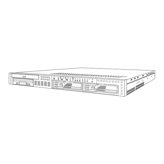
1.4 About the product About the product This section contains hardware diagrams and a block dia- gram of the GX28 system. 1.4.1 System front view and front panel See the diagram below for details of the front panel indicators and switches. LAN activity Power Reset... -
Page 14: System Internal View
1.4 About the product 1.4.3 System internal view LED control board Riser card Floppy disk drive (optional) Power connector Slim CD-ROM drive Memory slots Fan bracket EPS 12V 400W power supply SATA connector Processor sockets IDE connector SATA backplane FDD connector Front panel cable Chapter 1: Overview... -
Page 15: Block Diagram
1.4 About the product Block diagram 184 pin 184 pin 184 pin 184 pin LINK 0B DIMM0 DIMM1 DIMM2 DIMM3 16x16 Hyper Transport@1600MT/s 200-333MT/s Opteron Opteron Processor Processor 144-Bit SO-DIMM144 (ZCR) Adaptec 200-333MHz 144Bit AIC-7902 SCSI 16x16 Hyper Transport@1600MT/s AMD Chipset LINK 0A PCI-X Slots 64-Bit/133/100MHz... -
Page 16: Setting Up
Chapter 2: Setting up Before you begin This chapter explains how to install motherboard components including CPUs, memory modules, and PCI cards. There are also instructions in this section for installing SATA, SCSI, and IDE hard drives. Careful attention should be given to the precautions men- tioned in this section when setting up your system. -
Page 17: Precautions
2.1 Before you begin 2.1.3 Precautions Components and electronic circuit boards can be damaged by static electricity. Working on a system that is connected to a power supply can be extremely dangerous. Follow the guidelines below to avoid damage to the Transport GX28 or injury to yourself. -
Page 18: Installing Motherboard Components
2.2 Installing motherboard components Installing motherboard components This section describes how to install CPUs, memory mod- ules, and PCI cards. 2.2.1 Removing the chassis cover Follow these instructions to remove the GX28 chassis cover. This step is required before any other procedures in this chapter can be undertaken. -
Page 19: Installing Cpus
2.2 Installing motherboard components 2.2.2 Installing CPUs This section describes how to install AMD Opteron proces- sors and heatsinks in your GX28 system. This section applies to all models. 1. Remove the chassis cover as described in section 2.2.1 Removing the chassis cover. 2. - Page 20 2.2 Installing motherboard components 4. Lift the CPU locking lever as shown. 5. Place the CPU in the CPU socket, ensuring that pin 1 is located as shown. Pin 1 6. Press the CPU locking lever down to secure the CPU in the socket.
- Page 21 2.2 Installing motherboard components 9. Tighten the two screws on each heatsink to secure them in place. heatsinks 10. Replace the plastic air duct and secure with the single screw. Note: The GX28 should not be used with- out the air duct. Chapter 2: Setting up...
-
Page 22: Installing Memory
2.2 Installing motherboard components 2.2.3 Installing memory Follow the instructions in this section to install memory mod- ules in your GX28 system. 1. Remove the chassis cover as described in section 2.2.1 Removing the chassis cover. 2. Locate the memory slots on the motherboard. Memory slots 3. -
Page 23: Installing A Pci Card
2.2 Installing motherboard components 5. Insert the memory module into the slot as shown. The locking levers will fall into position. 6. Ensure that the locking levers are firmly in place and that the memory module is properly seated in the slot. 2.2.4 Installing a PCI card Follow the instructions in this section to install a PCI card in your GX28 system. - Page 24 2.2 Installing motherboard components 3. Remove the screw securing the PCI faceplate to the chassis. 4. Slide the PCI card clamp out as shown. 5. Slide the dust cover out. Chapter 2: Setting up...
- Page 25 2.2 Installing motherboard components 6. Press the PCI card into place in the slot on the riser card. Ensure that the card is seated properly in the slot on the riser card and that the riser card is properly seated in its slot on the motherboard.
- Page 26 2.2 Installing motherboard components 8. Insert the screw to secure the PCI card to the chassis. Chapter 2: Setting up...
-
Page 27: Installing A Sata Hard Drive
2.3 Installing a SATA hard drive Installing a SATA hard drive The GX28 supports SATA hard drives. Follow these instructions to install an external SATA hard drive in your GX28 system. 1. Press the drive bay locking latch in the direction of the arrow (1) and pull the locking lever open (2). - Page 28 2.3 Installing a SATA hard drive Note: If you are replacing an existing HDD, you will need to remove the four screws that secure it in the drive bay and remove it. 4. Insert four screws to secure the new unit in the drive bay. 5.
-
Page 29: Rack Mounting
2.4 Rack mounting Rack mounting Follow these instructions to mount the GX28 into an industry standard 19-inch rack. Note: Before mounting the Transport GX28 in a rack, ensure that all internal com- ponents have been installed and that the unit has been fully tested. - Page 30 2.4 Rack mounting Note: Ensure that the brackets with the cut away section (to accommodate the handles on the front of the unit) are fixed to the front end of the rail. 3. Fully extend the sliding rails until they lock. Note: Do not tighten the brackets to the rails as you will need to adjust their position...
- Page 31 2.4 Rack mounting Note: When fully extended, the sliding rails will lock. The release mechanism is located on the sliding rail as shown. Press the release mechanism while pushing the sliding rails to shorten them. 6. With the rails in their shortest position, adjust both front mounting brackets so that they are flush with the front of the unit.
- Page 32 2.4 Rack mounting 9. Lift the unit into place in the rack and screw it into place as shown. Note: To avoid injury, it is strongly recom- mended that two people lift the GX28 into place while a third person install it in the rack.
-
Page 34: Replacing Pre-Installed Components
Chapter 3: Replacing pre-installed components Introduction This chapter describes how to replace all the pre-installed components of your GX28, including PCI card, riser card, motherboard, CD-ROM drive, floppy disk drive, and LED con- trol board. There is also a section covering the replacement of the 2-port SATA backplane. - Page 35 3.2 Replacing motherboard components 1. Disconnect the power cables. Main power EPS 12V power 2. Disconnect the CD-ROM drive cable (A) and SATA hard drive cables (B) if installed. Chapter 3: Replacing pre-installed components...
- Page 36 3.2 Replacing motherboard components Note: If there is an FDD or IDE HDD installed in the bay beneath the CD-ROM drive, disconnect the FDD/HDD cables before removing the motherboard. 3. Disconnect the front panel LED and USB connectors. Front panel LED connector USB connector Chapter 3: Replacing pre-installed components...
-
Page 37: Replacing The Motherboard
3.2 Replacing motherboard components 3.2.2 Replacing the motherboard Follow these instructions to remove the motherboard from your GX28. Note: Before proceeding, you must remove all cable connections to the mother- board. See section 3.2.1 Disconnecting all motherboard cables. 1. Remove the fan assembly bracket from the chassis. 2. -
Page 38: Replacing The Slim Cd-Rom Drive
3.3 Replacing the slim CD-ROM drive 3. Remove the nine screws that secure the motherboard to the chassis. 4. Remove the motherboard from the chassis. Replacing the slim CD-ROM drive This section describes how to remove and replace the CD- ROM drive in your GX28 system. - Page 39 3.3 Replacing the slim CD-ROM drive 3. Remove the two screws that secure the CD-ROM back- plane to the CD-ROM drive. 4. Remove the four screws that secure the drive bay to the chassis and lift the drive bay free. 5.
-
Page 40: Replacing The Floppy Disk Drive
3.4 Replacing the floppy disk drive Replacing the floppy disk drive This chapter describes how to replace the floppy disk drive. 3.4.1 Replacing the floppy disk drive Follow these instructions to replace the FDD in your GX28. 1. Remove the chassis cover as described in section 2.2.1 Removing the chassis cover. -
Page 41: Replacing The Led Control Board
3.5 Replacing the LED control board Replacing the LED control board Follow these instructions to replace the LED control board. 1. Remove the two screws that secure the metal retaining plate to the chassis and lift it free. 2. Remove the front panel ribbon cable from the rear of the LED control panel. -
Page 42: Replacing The Storage Backplane
3.6 Replacing the storage backplane 3. Remove the two screws that secure the LED control panel to the chassis and lift the board free of the chassis. Replacing the storage backplane This section describes how to replace the SATA backplane on your GX28. - Page 43 3.6 Replacing the storage backplane 4. Remove the five screws that secure the SATA backplane bracket to the chassis. 5. Lift the backplane free of the chassis as shown. Chapter 3: Replacing pre-installed components...
-
Page 44: Replacing The Power Supply
3.7 Replacing the power supply Replacing the power supply Follow these instructions to replace the power supply in your GX28 system. 1. Remove the chassis cover as described in section 2.2.1 Removing the chassis cover. 2. Remove the four screws that secure the fan assembly to the chassis and lift it free. -
Page 45: Replacing The Cooling Fans
3.8 Replacing the cooling fans Replacing the cooling fans Follow these instructions to replace the cooling fans in your GX28 system. 1. Remove the chassis cover as described in section 2.2.1 Removing the chassis cover. 2. Remove the PCI retention bar. Note: You may need to cut the cable ties that secure the fan power cables before... - Page 46 3.8 Replacing the cooling fans 5. Remove the four screws securing each fan module to the fan holding bar to remove them. Note: When replacing fan modules it is important that each module is fitted the right way round. The sticker with the manufac- turer’s name should be nearest the mother- board when the fan module is installed.
-
Page 47: Cooling Fan Connections
3.8 Replacing the cooling fans 3.8.1 Cooling fan connections The three fan modules in the fan holding bar each house 2 fans. The fans towards the front of the bracket, marked 1, 2, and 3 in the diagram below, operate at up to 15,000 rpm and should be connected to the pin headers marked Fan 1, Fan 2, and Fan 3 on the Pin header diagram (section 3.8.2 Pin header diagram). -
Page 48: Pin Header Diagram
3.8 Replacing the cooling fans 3.8.2 Pin header diagram The diagram below shows the motherboard pin headers that supply power for the cooling fans. Pin headers labeled Fan 1, Fan 2, and Fan 3 auto fan speed control. Fan 2 Fan 4 Fan 1 USB1 (Bottom) -
Page 50: Appendix
BIOS Introduction Your Transport GX28 (B2882) system includes a powerful TYAN Thunder K8S S2882G3NR motherboard with AMI BIOS v8.0 on 4 MB flash ROM. The BIOS is the motherboard’s basic input/output system. The BIOS contains all the settings required to control the key- board, display, disk drives, serial communications, and a number of miscellaneous functions. - Page 51 BIOS setup utility Main Advanced PCI/PnP Boot Security Chipset Power Exit System Overview Use [Enter], [TAB] or AMIBIOS [SHIFT_TAB] to select Version :08.00.xx a field Build Date :7/17/2003 :0AAAA000 Use [+] or [-] to config- ure system time. Processor Type :AMD Opteron™...
-
Page 52: Bios Menu Bar
BIOS menu bar The menu bar at the top of the window lists the following selections: Menu bar selections Main To configure basic system setups Advanced Configure advanced chipset options PCI/PnP Configure legacy PnP or PCI settings Boot Configure system boot order Security Configure user and supervisor passwords Chipset... -
Page 53: Bios Legend Bar
BIOS legend bar The following chart describes the legend keys and their func- tions. BIOS legend bar Function <F1> or <Alt-H> General help window <ESC> Exit current window arrow keys Select a different window arrow keys Move cursor up/down <Tab> or <Shift-Tab> Cycle cursor up/down <Home>... -
Page 54: Bios Main Menu
BIOS main menu The Main BIOS menu is the first screen that appears when you enter BIOS setup. The menu has two main frames. The left frame displays all the options that can be configured. "Grayed-out" options cannot be configured, options in blue can be changed. -
Page 55: Bios Advanced Menu
BIOS advanced menu You can select any of the items in the left frame of the screen, such as Super I/O Configuration, to go to the sub- menu for that item. You can display an Advanced BIOS Setup option by highlighting it using the <Arrow> keys. All Advanced BIOS Setup options are described in this section. -
Page 56: Ide Configuration Submenu
BIOS advanced menu Features Option Description Advanced settings IDE Configuration Menu Item Configures devices connected to the AMD8111 IDE controller Floppy Configuration Menu Item Configures devices connected to the floppy controller Super I/O Configura- Menu Item Configures devices connected to tion the Super I/O controller Hardware Health Con-... - Page 57 IDE configuration submenu Main Advanced PCI/PnP Boot Security Chipset Power Exit IDE Configuration Use [Enter], [TAB] Onboard PCI IDE Controller [Both] or [SHIFT_TAB] to select a field Primary IDE Master : [xxxx] Primary IDE Slave : [xxxx] Use [+] or [-] to Secondary IDE Master : [xxxx] configure system...
-
Page 58: Floppy Configuration Submenu
Floppy configuration submenu Use this screen to change the floppy configuration settings. Use the up and down <Arrow> keys to select an item. Use the <Plus> and <Minus> keys to change the value of the selected option. Floppy configuration submenu Main Advanced PCI/PnP Boot Security Chipset Power Exit Floppy Configuration Use [Enter], [TAB] or... -
Page 59: Super I/O Configuration Submenu
Super I/O configuration submenu Use this screen to change the configuration of super I/O. Use the up and down <Arrow> keys to select an item. Use the <Plus> and <Minus> keys to change the value of the selected option. Super I/O configuration submenu Main Advanced PCI/PnP Boot Security Chipset Power Exit Win627 Super I/O chipset Use [Enter], [TAB] or... - Page 60 Super I/O configuration submenu Feature Option Description Win627 Super I/O Chipset Onboard • Enabled Enables or disables the onboard floppy floppy con- • Disabled controller troller Serial Port 1 • 3F8/IRQ4 Sets the serial port 1 (com 1) base I/O Address •...
-
Page 61: Hardware Health Event Monitoring Submenu
Hardware health event monitoring submenu You can use this screen to view the hardware health configu- ration Settings. Use the up and down <Arrow> keys to select an item. Use the <Plus> and <Minus> keys to change the value of the selected option. The settings are described on the following pages. - Page 62 Hardware health event monitoring submenu Feature Option Description Hardware Health Event Monitoring DIMM 2.5V VRM Temperature Displays CPU and ambient system temperatures. System Temperature CPU1 VRM Temperature CPU1 Temperature Displays CPU, ambient and VRM temperatures. CPU2 Temperature CPU2 VRM Temperature CPU1 Fan Speed Displays speed of fans con- nected to appropriate fan...
- Page 63 Motherboard voltages report submenu Main Advanced PCI/PnP Boot Security Chipset Power Exit Board Voltages Event Monitoring Use [Enter], [TAB] or [SHIFT_TAB] to select CPU1 Vcore x.xxx V a field CPU2 Vcore x.xxx V +3.3 Vin x.xxx V Use [+] or [-] to config- CPU2 DIMM Vref x.xxx V ure system time.
-
Page 64: Acpi Settings Submenu
ACPI settings submenu Use this screen to change options for ACPI. Use the up and down <Arrow> keys to select an item. Use the <Plus> and <Minus> keys to change the value of the selected option. A description of the selected item appears on the right side of the screen. -
Page 65: Advanced Acpi Configuration Submenu
Advanced ACPI configuration submenu Use this screen to select options for ACPI. Use the up and down <Arrow> keys to select an item. Use the <Plus> and <Minus> keys to change the value of the selected option. A description of the selected item appears on the right side of the screen. -
Page 66: Event Logging Details Submenu
Event logging details submenu You can use this screen to view the event log control menu. This logs system events (such as CMOS clear, ECC memory errors, etc.) and writes the log into NVRAM. Use the up and down <Arrow> keys to select an item. Use the <Plus> and <Minus>... -
Page 67: Hyper Transport Configuration Submenu
Hyper transport configuration submenu Use this screen to view the hyper transport configuration Menu and make changes. Use the up and down <Arrow> keys to select an item. Use the <Plus> and <Minus> keys to change the value of the selected option. Hyper transport configuration submenu Main Advanced PCI/PnP Boot Security Chipset Power Exit Hyper Transport Configuration... -
Page 68: Device And Pci Slots Configuration Submenu
Hyper transport configuration submenu Feature Option Description Configure Remote Access Type and Parameters CPU1: CPU2 • Auto Specifies CPU1 to CPU2 Hyper Trans- HT Link Speed • 200 MHz port Link Clock frequency. If CPU2 is • 400 MHz absent, this option will be hidden. •... - Page 69 • Ultra Allows user to select mode for mode • RAID serial ATA. Check Web site for serial ATA RAID support: http://www.tyan.com Gigabit LAN option • Enabled Allows user to enable or disable • Disabled onboard gigabit LAN controller option ROM (PXE Enabled/Dis-...
- Page 70 Device and PCI slots configuration Feature Option Description Onboard device and PCI slot configuration 100/10 Mbit LAN • Enabled Allows user to enable or disable option ROM • Disabled onboard 100/10 Mbit LAN controller option ROM (PXE Enabled/Disabled) PCI1 slot (64 bit) •...
-
Page 71: Remote Access Configuration Submenu
Remote access configuration submenu Use this screen to view the remote access configuration menu. This feature allows remote access to the Server using the serial port. Use the up and down <Arrow> keys to select an item. Use the <Plus> and <Minus> keys to change the value of the selected option. - Page 72 Configure remote access type and parameters Feature Option Description Configure remote access type and parameters Remote • SMDC Enables remote access to system access • Enabled through serial port. • Disabled Serial port • COM 1 Select serial port for console redirection. number •...
-
Page 73: Usb Configuration Submenu
USB configuration submenu Use this screen to view the USB configuration menu. Use the up and down <Arrow> keys to select an item. Use the <Plus> and <Minus> keys to change the value of the selected option. The settings are described on the following pages. USB configuration menu Main Advanced PCI/PnP Boot Security Chipset Power Exit USB Configuration... - Page 74 USB configuration submenu Feature Option Description USB Configuration Legacy USB • Auto Enables support for legacy USB devices Support • Disabled such as keyboards, mice and bootable • Enabled USB devices. USB key- • Disabled Select “Enabled” if your system contains board legacy •...
-
Page 75: Advanced Pci/Pnp Menu
Advanced PCI/PnP menu Use this screen to view PnP (Plug & Play) BIOS Configura- tion Menu. This menu allows the user to configure how the BIOS assigns resources & resolves conflicts. Use the up and down <Arrow> keys to select an item. Use the <Plus> and <Minus>... - Page 76 Advanced PCI/PnP Menu Feature Option Description Advanced PCI/PnP Menu Plug & Play OS • Yes The Yes setting allows the operating • No system to change the interrupt, I/O, and DMA settings. Set this option to Yes only if the system is running Plug and Play aware operating sys- tems.
-
Page 77: Bios Boot Settings Menu
BIOS boot settings menu You can display the boot settings option by highlighting it using the <Arrow> keys and pressing <Enter>. BIOS boot settings menu Main Advanced PCI/PnP Boot Security Chipset Power Exit Boot Settings Use [Enter], [TAB] or Boot Settings Configuration [SHIFT_TAB] to select a field Boot Device Priority... -
Page 78: Boot Settings Configuration Submenu
Boot settings configuration submenu Use this screen to select options for the boot settings configu- ration. Use the up and down <Arrow> keys to select an item. Use the <Plus> and <Minus> keys to change the value of the selected option. Boot settings configuration submenu Main Advanced PCI/PnP Boot Security Chipset Power Exit Boot Settings Configuration... - Page 79 Boot settings configuration submenu Feature Option Description Boot Settings Configuration Quick Boot Mode • Enabled Allows user bypass BIOS self • Disabled test during POST. Quiet Boot • Disabled Enable this option to hide BIOS • Enabled Post messages during POST Add On ROM Dis- •...
-
Page 80: Boot Device Priority Submenu
Boot device priority submenu Use this screen to select options for the boot device priority. Use the up and down <Arrow> keys to select an item. Use the <Plus> and <Minus> keys to change the value of the selected option. Boot device priority submenu Main Advanced PCI/PnP Boot Security Chipset Power Exit Boot Device Priority... -
Page 81: Hard Disk Submenu
Hard disk submenu Use this screen to select options for the hard disk drives. Use the up and down <Arrow> keys to select an item. Use the <Plus> and <Minus> keys to change the value of the selected option. Hard disk drives submenu Main Advanced PCI/PnP Boot Security Chipset Power Exit Hard Disk Drives Use [Enter], [TAB] or... -
Page 82: Removable Drives Submenu
Removable drives submenu Use this screen to select options for the removable drives. Use the up and down <Arrow> keys to select an item. Use the <Plus> and <Minus> keys to change the value of the selected option. Removable drives submenu Main Advanced PCI/PnP Boot Security Chipset Power Exit Removable Drives Use [Enter], [TAB] or... -
Page 83: Atapi Cd-Rom Drives Submenu
ATAPI CD-ROM drives submenu Use this screen to select options for the ATAPI CD-ROM drives. Use the up and down <Arrow> keys to select an item. Use the <Plus> and <Minus> keys to change the value of the selected option. ATAPI CD-ROM drives submenu Main Advanced PCI/PnP Boot Security Chipset Power Exit ATAPI CD-ROM Drives... -
Page 84: Bios Security Menu
BIOS security menu The system can be configured so that all users must enter a password every time the system boots or when BIOS Setup is entered, using either the Supervisor password or User password. The Supervisor and User passwords activate two different levels of password security. - Page 85 BIOS security menu Feature Option Description Security Settings Supervisor Not Installed If the password has been set, Installed dis- Password Installed plays. If no password is set, Not Installed displays. User Not Installed If the password has been set, Installed dis- Password Installed plays.
-
Page 86: Bios Chipset Settings
BIOS chipset settings This menu enables the user to customize functions of the Intel Chipset. Select a menu by highlighting it using the <Arrow> keys and pressing <Enter>. BIOS chipset settings Main Advanced PCI/PnP Boot Security Chipset Power Exit Chipset Settings Use [Enter], [TAB] or [SHIFT_TAB] to select Intel E7500/E7501 Northbridge... -
Page 87: Northbridge Chipset Configuration Submenu
Northbridge chipset configuration submenu This menu gives options for the northbridge chipset configu- ration settings. Select a menu by highlighting it using the <Arrow> keys and pressing <Enter>. Northbridge chipset configuration menu Main Advanced PCI/PnP Boot Security Chipset Power Exit Northbridge Bridge Chipset Configuration Use [Enter], [TAB] or [SHIFT_TAB] to select... -
Page 88: Memory Configuration Submenu
Memory configuration submenu This menu gives options for memory speed and latency. Select a menu by highlighting it using the <Arrow> keys and pressing <Enter>. Main Advanced PCI/PnP Boot Security Chipset Power Exit Memory Configuration Use [Enter], [TAB] or [SHIFT_TAB] to select Bank Interleaving [Auto] a field... -
Page 89: Ecc Configuration Submenu
ECC configuration submenu Use this menu to view and make changes to the ECC (Error Correcting Code) setup for system and DRAM. Use the up and down <Arrow> keys to select an item. Use the <Plus> and <Minus> keys to change the value of the selected option. Main Advanced PCI/PnP Boot Security Chipset Power Exit Memory Configuration Use [Enter], [TAB] or... - Page 90 ECC configuration submenu Feature Option Description ECC Configuration DRAM BG • 10.2 us DRAM scrubbing corrects and rewrites Scrub • 20.5 us memory errors so later reads are cor- • 41.0 us rect. Doing this while memory is not • 81.9 us being used improves performance.
- Page 91 Feature Option Description Data Cache BG • Disabled Allows the L1 Data Cache RAM to be Scrub • 40ns corrected while idle. • 80ns • 160ns • 320ns • 640ns • 1.28us • 2.56us • 5.12us • 10.2us • 20.5us •...
-
Page 92: Southbridge Chipset Configuration Submenu
Southbridge chipset configuration submenu This menu gives options for southbridge chipset configuration settings. Use the up and down <Arrow> keys to select an item. Use the <Plus> and <Minus> keys to change the value of the selected option. Southbridge chipset configuration menu Main Advanced PCI/PnP Boot Security Chipset Power Exit Southbridge Chipset Configuration Use [Enter], [TAB] or... - Page 93 Southbridge chipset configuration submenu Feature Option Description Southbridge chipset configuration 2.0 SM Bus • Enabled Enables or disables the SM bus 2.0 Controller • Disabled controller in the AMD8111 I/O hub. HT Link 0 P- • Auto Auto uses hardware compensation Comp Mode •...
-
Page 94: Pci-X Chipset Configuration Submenu
PCI-X chipset configuration submenu This menu allows the user to configure Hyper Transport data compensation settings. Select a menu by highlighting it using the <Arrow> keys and pressing <Enter>. Intel PCI-64 Hub 2 configuration submenu Main Advanced PCI/PnP Boot Security Chipset Power Exit PCI-X Chipset Configuration Use [Enter], [TAB] or [SHIFT_TAB] to select... - Page 95 PCI-X chipset configuration Feature Option Description PCI-X chipset configuration HT Link 0 P- • Auto Auto uses hardware compensa- Comp Mode • Data tion values. Other values add to • CalComp+Data or subtract from hardware gener- • CalComp-Data ated value. Recommended set- ting is Auto.
-
Page 96: Bios Power Menu
BIOS power Menu This menu enables the user to configure power management settings. Select a menu by highlighting it using the <Arrow> keys and pressing <Enter>. Main Advanced PCI/PnP Boot Security Chipset Power Exit PCI-X Chipset Configuration Use [Enter], [TAB] or [SHIFT_TAB] to select Power Management [Enabled]... - Page 97 BIOS power menu Feature Option Description APM Configuration Power Manage- • Disabled Enabled setting allows the chipset ment/APM • Enabled power management and APM fea- tures. Resume On Ring • Disabled When enabled, any event occur- • Enabled ring to the COM Ring will awaken a powered down system.
-
Page 98: Bios Exit Menu
BIOS exit menu Display an exit BIOS setup option by highlighting it with the <Arrow> keys and pressing <Enter>. BIOS exit menu Main Advanced PCI/PnP Boot Security Chipset Power Exit Exit Options Use [Enter], [TAB] or [SHIFT_TAB] to select Save Changes and Exit a field Discard Changes and Exit Discard Changes... - Page 99 BIOS exit menu Feature Option Description Save Changes and Exit Use this option to exit setup and Changes you have reboot. made are stored into CMOS. Discard Changes and Exit Use this option to exit setup and reboot. Changes you have made are not stored in CMOS.
-
Page 100: Technical Support
Help resources: 1. See the beep codes section in the motherboard manual 2. See the TYAN website for FAQs, bulletins, driver updates and other information: http://www.tyan.com 3. Only contact TYAN after first speaking with your dealer 4. Check the TYAN user group: alt.comp.periphs.mainboard.TYAN...
Need help?
Do you have a question about the Transport GX28 B2882 and is the answer not in the manual?
Questions and answers