Table of Contents
Advertisement
Quick Links
Advertisement
Table of Contents

Related Manuals for TYAN Tank GT25 (B5381


Summary of Contents for TYAN Tank GT25 (B5381
- Page 1 Tank GT25 B5381 Service Engineer’s Manual...
- Page 3 ® TYAN and Tank GT25 B5381 are trademarks of MiTAC Interna- tional Corporationn. Intel, Xeon, and combinations thereof are trademarks of Intel Corpo- ration.
- Page 4 Federal Communications Commission (FCC) Notice for the USA Compliance Information State- ment (Declaration of Conformity Procedure) DoC FCC Part 15: This device complies with part 15 of the FCC Rules Operation is subject to the following conditions: 1) This device may not cause harmful interference, and 2) This device must accept any interference received including inter- ference that may cause undesired operation.
- Page 5 Provides information on installing SMDC cards. Appendix: Describes how to make a driver diskette. The cable connection tables is also provided for refer- ence of system setup. For information on the SAS controller software, please refer to the following web sites: ftp://ftp.tyan.com/manuals/m_install_LSI-SAS.pdf ftp://ftp.tyan.com/manuals/m_LSI_SAS_1068E.pdf...
- Page 6 SAFETY INFORMATION Before installing and using the Tank GT25, take note of the following precautions: – Read all instructions carefully. – Do not place the unit on an unstable surface, cart, or stand. – Do not block the slots and opening on the unit, which are pro- vided for ventilation.
-
Page 7: Table Of Contents
Table of Contents Chapter 1:Overview 1.1 About the Tank GT25 B5381 ......1 1.2 Features . - Page 8 6.2 SMDC Information ........106 Appendix I: Cable Connection Tables Appendix II: How to Make a Driver Diskette Technical Support...
-
Page 9: Chapter 1:Overview
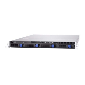
Chapter 1: Overview About the Tank GT25 B5381 ® Congratulations on your purchase of the TYAN Tank GT25 B5381, a highly-optimized rack-mountable barebone system. The Tank GT25 B5381 is designed to support dual ® ® Intel Xeon 5000 series processors, providing a rich feature set and incredible performance. -
Page 10: Features
(1) full height/full length add-on PCI-X (M2055) or PCI-E (M2082) Motherboard card ® • TYAN S5381 system board • Aligned (1) 64-bit/133MHz PCI-X • Customized 15”x16” (381x406mm) slot and (1) x8 PCI-E slot, support- BIOS ing (1) low-profile PCI-X (M2057) or PCI-E (M2086) add-on card •... - Page 11 Server Management • System fan speed control and moni- toring • Chassis intrusion alert ® • Supports TYAN Server Manage- ment (TSM) ® • TYAN SMDC, M3291, IPMI 2.0 compliant remote server manage- ment kit (optional) System Cooling • (7) 40*40*56mm 15800rpm heavy- duty fans •...
-
Page 12: Unpacking
Unpacking This section describes the Tank GT25 B5381 package con- tents and accessories. 1.3.1 Opening the Box Open the box carefully and ensure that all components are present and undamaged. The product should arrive pack- aged as illustrated below. Packaged accessories Chapter 1: Overview... -
Page 13: Box Contents
1.3.2 Box Contents Component Description Industry standard 1U chassis, (4) hot-swap HDD bays ® TYAN S5381 system board (pre-installed) 8x slim DVD-ROM drive (pre-installed) M1003 LED and USB control board (pre- installed) B5381G25W4H: (A) B5381G25W4HR: (B), (C) (7) System fans (40 mm x 56 mm) - Page 14 Component Description M1210 Adapter board M5002 FPC cable Chapter 1: Overview...
- Page 15 If any items are missing or appear damaged, contact your ® retailer or browse to TYAN ’s website for service: http://www.tyan.com. ® The Web site also provides information on other TYAN products, plus FAQs, compatibility lists, BIOS settings, and more. ® 1 x TYAN Driver CD...
- Page 16 Rail Kit Mounting Bracket x 4 Screw Kit Sliding Rail x 2 Sliding Brackets Front L-Bracket x 2 Rear L-Bracket x 2 FDD Kit FDD Backplane Cable FDD Cable FDD Rails & Screws Chapter 1: Overview...
-
Page 17: About The Product
About the Product The following views show you the product. 1.4.1 Front View Reset switch Warning LED NMI switch HDD activity LED ID Switch Power LED ID LED DVD-ROM Drive Power switch USB ports 2 x LAN LEDs Hard Drive Bay x 4 1.4.2 Rear View Case A (Single Power) COM1... -
Page 18: Led Definitions
Case B (Redundant Power) COM1 PCI-X Port Port Slot Power Supply Sockets ID LED Ports PS/2 Power Supply Fans PCI-E ID Switch Key- Slot board SAS B5381G25W4H (Optional) Port LAN Port (NIC2) LAN Port (NIC1) 1.4.3 LED Definitions Front Panel Color State Description... - Page 19 Rear I/O LED Right or Left is viewed from the rear. Color State Description RJ45 NIC1 Linkage Green Linked to LAN (Left Side) Green Blinking Accessing LAN No LAN link RJ45 NIC1 Mode Yellow Gigabit mode (Right Side) Green 100M mode 10M mode RJ45 NIC2 Linkage Green...
- Page 20 1.4.4 Internal View Case A - Single Power Fan13 Fan1 Fan14 Fan2 1. Power Supply 8. M1210 Adapter Board 2. SAS Connector 9. Four SATA / SAS HDD Bays 3. Link Bar 10. LED Control Board Cable 4. Fully Buffered DIMM Memory 11.
- Page 21 Case B - Redundant Power Fan13 Fan1 Fan14 Fan2 1. Power Supply 8. M1210 Adapter Board 2. SAS External Connector 9. Four SATA / SAS HDD Bays 3. Link Bar 10. LED Control Board Cable 4. Fully Buffered DIMM Memory 11.
- Page 22 1.4.5 Motherboard Block Diagram Chapter 1: Overview...
-
Page 23: Motherboard Layout
1.4.6 Motherboard Layout 1. DIMM Slots 11. PCI-X Slot 2. TEMP Sensor 12. ID LED 3. CPU1 13. ID SW 4. CPU2 14. SAS Output Connector 5. SATA Connector 15. USB 6. SAS Connector 16. LAN 2 7. FPIO Connector 17. - Page 24 Jumpers & Connectors Jumper Function /Connector Clear CMOS Jumper (Close 1-2) Default (Close 2-3) Clear CMOS SMDC Connector SAS 2 SAS Connector SATA Connector Front Panel Connector Chapter 1: Overview...
-
Page 25: Fru List
FRU List GT25-B5381 Standard Parts Item Model Number Picture Quantity Description Motherboard S5381G3NR TF-Motherboard; Tyan S5381 Chassis Unit CCHA-0120 TF-CHASSIS UNIT;GT25 CPSU-0113 B5381G25W4H Power Supply CPSU-0120 B5381G25W4HR CPSU-0121 B5381G25W4HR CFAN-0065 TF-Fan Assy; SanyoDenki 40x40x56 TF-Heatsink backplane, CEK SPRING Heat Sink & Cooler CHSB-0080 FOR LGA771 Heat Sink &... - Page 26 GT25-B5381 Standard Parts Model Item Picture Quantity Description Number M2055-RS TF-PWA, TF-PCI-X 1U riser card M2082-RS TF-PWA, PCI-E X8 1U riser card Riser Card M2057-RS TF-PWA, PCI-X 1U riser card M2086-RS TF-PWA, TF-PCI-E X16 1U riser card CRAL-0080 TF-RAIL ASSY;26" FOR GT25 Rack Mounting Part CEAR-0050...
- Page 27 GT25-B5381 Standard Parts Item Model Number Picture Quantity Description Optional Part Peripheral Drives& CFDD-0020 Floppy disk drive, slim type parts TF-LCD module kit for GT series 1U LCD Module CLCM-0040 chassis Chassis Front TF-Front bezel assembly for GT series CFBZ-0070 Bezel 1U chassis Chapter 1: Overview...
- Page 28 NOTE Chapter 1: Overview...
-
Page 29: Chapter 2:Setting Up
Chapter 2: Setting Up 2.0.1 Before You Begin This chapter explains how to install the CPU, CPU heatsink, memory modules, and hard drives. Instructions on inserting a PCI card are also given. Take note of the precautions mentioned in this section when installing your system. - Page 30 2.0.4 Precautions Components and electronic circuit boards can be damaged by discharges of static electricity. Working on a system that is connected to a power supply can be extremely dangerous. Follow the guidelines below to avoid damage to the Tank GT25 or injury to yourself. •...
-
Page 31: Rack Mounting
Rack Mounting After installing the necessary components, the Tank GT25 can be mounted in a rack using the supplied rack mounting kit. Rack mounting kit Sliding Rails x 2: Sliding Brackets x 4 (Front x 2, Rear x 2) Mounting Ears x 2 Screws Kit x 1 Mounting Brackets x 4 2.1.1 Installing the Server in a Rack... - Page 32 Installing the Inner Rails to Chassis 1. Screw the mounting ear to each side of GT25 as shown using 2 screws from the supplied screws kit. Mounting Ears 2. Draw out the inner rails from rail assembly. Install inner rails to left and right sides of chassis using 2 M4-5L(D) screws for each side.
- Page 33 2. Locate the front and rear brackets. Rear Bracket x2 Front Bracket x2 3. Reserve 90mm for GT25 on the front bracket. Secure the front bracket to outer rail with 2 M4-4L(C) screws. 4. Reserve the distance same as in Step 2 on rear bracket. Secure the rear bracket to outer rail with 2 M4-4L(C) screws.
- Page 34 5. Secure the outer rail to the rack using 2 brackets and 4 M4-8L(E) screws for each side (A). Secure the mounting brackets from inside, not outside, of the rack (B). Mounting Bracket Chapter 2: Setting Up...
- Page 35 Rackmounting the Server 6. Draw out the middle rail to the latch position. 7. Lift the chassis and then insert the inner slide rails into the middle rails. 8. Push the chassis in and press the latch key (A). Then push the whole system into the rack (B).
- Page 36 9. Secure the mounting ears of chassis to the rack with 2 M4-15L(F) screws. Note: To avoid injury, it is strongly recommended that two people lift the GT25 into the place while a third person screws it to the rack. Chapter 2: Setting Up...
-
Page 37: Installing Motherboard Components
Installing Motherboard Components This section describes how to install components on to the motherboard, including CPU, memory modules, and PCI card. 2.2.1 Removing the Chassis Cover Follow these instructions to remove the Tank GT25 chassis cover. 1. Remove the screw on the back side. Then slide the chas- sis cover in the direction of arrow. - Page 38 2.2.2 Installing the Memory Follow these instructions to install the memory modules on the motherboard. Note: There are 12 DIMM memory slots available. When installing RAM in both slots, begin installation from DIMM1 and install in sequence according to the slot number. 1.
- Page 39 4. Align the memory module with the slot. When inserted properly, the memory slot locking levers lock automati- cally onto the indentations at the ends of the module. For optimal system operation, please install memory in pairs. Chapter 2: Setting Up...
- Page 40 Memory Population Table Single Dual Four Four DIMM / Channel DIMM1 (A0) DIMM2 (A1) DIMM3 (A2) DIMM4 (B0) DIMM5 (B1) DIMM6 (B2) DIMM7 (C0) DIMM8 (C1) DIMM9 (C2) DIMM10 (D0) DIMM11 (D1) DIMM12 (D2) NOTE: Please always install memory beginning with DIMM1. You can choose to install single, dual or four channel population.
- Page 41 2.2.3 Installing the CPU and Heatsink 1. Follow these instructions to install CPU1, CPU2 and the CPU heatsink. 2. Locate the CPU sockets. CPU1 CPU2 3. Unlatch the CPU lever to release the CPU cover. Chapter 2: Setting Up...
- Page 42 4. Pull the lever arm up to unlock the CPU cover. 5. Gently lift up the cover. 6. Place the CPU in the CPU socket, ensuring that Pin 1 is correctly aligned. Chapter 2: Setting Up...
- Page 43 7. Close the cover and attach the latch to secure. 8. Align the heatsink screw holes with the holes on the motherboard and insert heatsink screws as shown. 9. Secure the heatsink to the motherboard. 10. Replace the steps above to install a second CPU. Chapter 2: Setting Up...
- Page 44 2.2.4 Installing the PCI-X Card Follow these instructions to install a PCI-X card. 1. Push the latch of PCI-X slot on the rear panel in the direc- tion as shown to release the PCI bracket. 2. Move the PCI bracket to right as shown and take it off. 3.
- Page 45 2.2.5 Installing the SCSI Card Follow these instructions to install a SCSI card. 1. Push the latch of PCI-X slot on the rear panel in the direc- tion as shown to release the PCI bracket. 2. Take off the PCI bracket. 3.
- Page 46 4. Insert the SCSI card in the slot. 5. Replace the link bar and screw it firmly to the chassis. Chapter 2: Setting Up...
- Page 47 6. Replace the PCI bracket and reattach the slot latch. Chapter 2: Setting Up...
-
Page 48: Installing The External Hard Drive
Installing the External Hard Drive The GT25 chassis kit supports external SATA/SAS hard drives. Follow these instructions to install an external SATA or SCSI hard drive. 1. Press the locking lever latch in the direction of arrow (A) and then pull the locking lever open (B). 2. - Page 49 4. Using 4 HDD screws to secure the HDD. 5. Reinsert the drive tray into the chassis (A), ensuring that the drive tray is completely inserted into the chassis (B). 6. Pressing the locking lever to secure the hard drive tray. Chapter 2: Setting Up...
-
Page 50: Installing The Slim Fdd (Option)
Installing the Slim FDD (Optional) 1. Locate the two FDD rails and screws from the FDD kit. Secure the two rails to the FDD using four screws. FDD Rails & Screws 2. Connect the FFC cable to the FDD. 3. Using a screw driver to pull open the door of the FDD tray. - Page 51 4. Insert FDD module into the tray. 5. Connect the FFC cable to the connector on the M1210 adapter board. 6. Locate the FDD cable from FDD kit. Connect the wrinkle side to the connector on M1210 adapter board. Chapter 2: Setting Up...
- Page 52 NOTE Chapter 2: Setting Up...
-
Page 53: Chapter 3:Replacing Pre-Installed Components
Chapter 3: Replacing Pre-Installed Components Introduction This chapter explains how to replace pre-installed compo- nents including the motherboard, LED control board, HDD, and DVD-ROM drive. Take note of the precautions in this section when installing your system. 3.1.1 Work Area Make sure you have a stable, clean working environment. - Page 54 3.1.3 Precautions Components and electronic circuit boards can be damaged by static electricity. Working on a system that is connected to a power supply can be extremely dangerous. Follow the guidelines below to avoid damage to the GT25 or injury to yourself.
-
Page 55: Disassembly Flowchart
Disassembly Flowchart The following flowchart outlines the disassembly procedure. Rear Components DIMMs Chassis rear cover CPU/heatsink assembly Mainboard PCI card Power supply Mainboard Front Components Chassis rear cover PCBs DVD-ROM Control M1210 Board Adapter Board Chapter 3: Replacing Pre-Installed Components... -
Page 56: Removing The Cover
Removing the Cover Before replacing any parts you must remove the chassis cover. Follow these instructions to remove the cover of the Tank GT25 chassis cover. 1. Remove the screw on the back side. Then slide the chas- sis cover in the direction of arrow. 2. -
Page 57: Replacing Motherboard Components
Replacing Motherboard Components Follow these instructions to replace motherboard compo- nents, including the motherboard. 3.4.1 Disconnecting All Motherboard Cables Before replacing the motherboard or certain components, remove cables connected to the motherboard. Follow these instructions to remove all motherboard cabling. 1. - Page 58 3.4.2 Removing the Motherboard After removing all of the aforementioned cables, follow these instructions to remove the motherboard from the chassis. 1. Remove the link bar. 2. Remove the fifteen screws securing the motherboard to the chassis. 3. Remove the motherboard. Chapter 3: Replacing Pre-Installed Components...
-
Page 59: Replacing The Slim Cd-Rom
Replacing the Slim DVD-ROM Follow these instructions to replace the DVD-ROM. 1. Remove power and data cables from the slim DVD-ROM adapter. 2. Press the tab in the directions as shown to release the DVD-ROM drive. 3. The DVD-ROM drive will be freed from the drive bay after pressing the tab. - Page 60 4. Remove the two screws that secure DVD-ROM drive to the bracket. 5. Replace the DVD-ROM drive and secure to the bracket using two screws. Then replace the unit into the drive bay and connect the DVD-ROM power and data cables as in steps 1 and 2.
-
Page 61: Replacing The Led Control Board
Replacing the LED Control Board Follow these instructions to replace the LED control board. 1. Remove the two screws securing the LED control board unit to the chassis. 2. Lift the LED control board unit free of the chassis. 3. Remove three screws securing LED control board to the bracket. - Page 62 4. Lift the LED control board free from the chassis. After replacement, insert the unit into the chassis. Chapter 3: Replacing Pre-Installed Components...
-
Page 63: Replacing The M1012 Adapter Board
Replacing the M1210 Adapter Board 1. Remove all of those cables connected to the adapter board, including fan cables, DVD-ROM power cable, front LED panel cable, power cables, and SATA cables. Refer to the photos below for locations. Chapter 3: Replacing Pre-Installed Components... - Page 64 2. Remove the fans. 3. Remove six screws to release the adapter board. Chapter 3: Replacing Pre-Installed Components...
- Page 65 3.7.1 M1210 Adapter Board Features for B5381 Fan 13, 14 Connector Case Open Connector CD-ROM Power Connector SAS/SATA HDD Connector Power Connectors FPIO Connector HDD Power LED (Green) HDD Activity LED (Yellow) IDE Connector Front Panel Connector Front USB Connector SAS/SATA HDD Connector Front COM Connector...
-
Page 66: System Fan Layout
3.7.2 System Fan Layout The following table provides the information for system fan layout. System Fan Speed Control Signal M1210 Adapter Board Connect to Motherboard J16 (FPIO) J11 (FPIO) 3.7.3 M1210 Adapter Board Connector Pin Definitions J14 Front Panel Connector HDLED+ HDLED- RESET+... - Page 67 J3 Chassis Instruction Pin Header INTRU# FAN Signal Related Connector Pin Definitions NOTE: The FAN signal naming is based on HW circuit design only. It might be different from the system fan naming. J4 Fan Connector PWM1 VCC12 FAN1_TACH FAN2_TACH VCC12 PWM2 J5 Fan Connector...
- Page 68 J6 Fan Connector PWM1 VCC12 FAN5_TACH FAN6_TACH VCC12 PWM2 J7 Fan Connector PWM1 VCC12 FAN7_TACH FAN8_TACH VCC12 PWM2 Chapter 3: Replacing Pre-Installed Components...
- Page 69 J8 Fan Connector PWM1 VCC12 FAN9_TACH FAN10_TACH VCC12 PWM2 J9 Fan Connector PWM1 VCC12 FAN11_TACH FAN12_TACH VCC12 PWM2 Chapter 3: Replacing Pre-Installed Components...
- Page 70 J10 Fan Connector PWM1 VCC12 FAN13_TACH FAN14_TACH VCC12 PWM2 J1 LCM Connectors LCM_+5V LCM_SIN KEY PIN LCM_+5VSB LCM_SOUT Chapter 3: Replacing Pre-Installed Components...
-
Page 71: Replacing The Power Supply
Replacing Power Supply 3.8.1 Replacing A Redundant Power Supply 1. Push the power supply unit latch inwards. 2. Pull out the power supply unit as shown. 3. Replace the unit with the new power supply following the steps above in reverse. Chapter 3: Replacing Pre-Installed Components... - Page 72 3.8.2 Replacing A Single Power Supply To replace the power supply follow these instructions. 1. Disconnect all power cables. 2. Unscrew to remove the power supply cover as shown. 3. Slide out the power supply unit and replace with a new one following the steps above in reverse.
- Page 73 3.8.3 Replacing Redundant with Single Power Supply To replace the power supply follow these instructions. 1. Remove the first row of screws from the top of the power supply casing. Slide the bracket to the right. 2. Remove the second row of screws from the top of the power supply casing.
- Page 74 4. Unscrew to remove the power supply cover as shown. 5. Slide out the power supply unit and replace with a new one following the steps above in reverse. Chapter 3: Replacing Pre-Installed Components...
-
Page 75: Chapter 4:Bios Setup
Chapter 4: BIOS Setup About the BIOS The BIOS is the basic input/output system, the firmware on the motherboard that enables your hardware to interface with your software. The BIOS determines what a computer can do without accessing programs from a disk. The BIOS contains all the code required to control the keyboard, display screen, disk drives, serial communications, and a number of miscella- neous functions. - Page 76 Chipset section unless you are absolutely sure of what you are doing. The Chipset defaults have been carefully chosen either by TYAN or your system manufacturer for best perfor- mance and reliability. Even a seemingly small change to the Chipset setup options may cause the system to become unstable or unusable.
-
Page 77: Bios Main Menu
BIOS Main Menu In this section, you can alter general features such as the date and time, as well as access to the IDE configuration options. Note that the options listed below are for options that can directly be changed within the Main Setup screen. System Time / Date setup System Time: Adjusts the system clock. - Page 78 System Memory This display allows you to change the amount of system memory present on the system. Extended Memory This displays/allows you to change the amount of extended memory present on the system. 4.2.1 IDE Primary/Secondary Master/Slave Setup Computer detects IDE drive type from drive C to drive F. Press Enter on any of the Primary/Master, Primary/Slave, Second- ary/Master, Secondary/Slave options to view advanced details of the corresponding drive.
- Page 79 Multi-Sector Transfers This option allows you to specify the number of sectors per block for multiple sector transfers. 16 Sectors / 2 Sectors / 4 Sectors / 8 Sectors /Disabled LBA Mode Control Enables or disables LBA Mode. When LBA is turned on, the BIOS will enable geometry translation. This translation may be done in the same way that it is done in Extended CHS or large mode, or it may be done using a different algorithm called LBA-assist translation.
-
Page 80: Boot Features
4.2.2 Boot Features This option allows setting boot parameters. Press Enter to view the Boot Features screen. Floppy Check This feature is used to verify floppy type on boot. Selecting “Disabled” will speed the boot process. Disabled / Enabled Summary Screen Enables or disables the display of the summary screen during boot up. - Page 81 computer by shortening or skipping certain standard booting procedures. If enabled, the BIOS will shorten the booting process by skipping some tests and shortening others. In addition, it will also perform the following to further speed up the booting process: Spin up the hard disks as soon as power is supplied (or as soon as possible) Initialize only critical parts of the chipset...
-
Page 82: Advanced Menu
Advanced Menu This section facilitates configuring advanced BIOS options for your system. Installed OS Select the operating system installed on the PC. Note: An incorrect setting can cause the operating system to behave unpre- dictably. Win OS / Other Reset Configuration Data If you install a new piece of hardware or modify your computer's hardware configuration, the BIOS will automatically detect the changes and reconfigure the ESCD (Extended SystemConfiguration Data). - Page 83 ally disable this feature after rebooting. Yes / No Large Disk Access Mode This option determines whether a hard drive with more than 1024 cylinders, more than 16 heads and or more than 64 tracks per sector is present on the system.
-
Page 84: Advanced Chipset Control
4.3.1 Advanced Chipset Control This section allows you to fine tune the chipset configuration. Crystal Beach Configure Enable Enable the configuration of memory mapped accesses to the Crystal Beach Configuration space located in Device 8, Fn 0 and Fn 1. Enabled / Disabled Parallel ATA This feature is used to enable the PATA functionality. - Page 85 “Enhanced (non-AHCI) mode”, SATA and PATA drives are auto-detected and placed in Native IDE mode. Compatible / Enhanced (non-AHCI) SATA RAID Enable This feature is used to enable the SATA RAID functionality. Enabled / Disabled SATA AHCI Enable This feature is used to enhance AHCI mode. Enabled / Disabled Chapter 4: BIOS Setup...
- Page 86 4.3.1.1 FBD Memory Configuration Submenu SERR signal condition Select ECC error conditions that SERR# be asserted. None / Single bit / Multiple bit/ Both 4GB PCI Hole Granularity It is used to select the granularity of PCI hole for PCI resource. If MTRRs are not enough, we may use this option to reduce the MTRR occupation.
- Page 87 4.3.1.2 PCI/PCI-E Device Control Submenu Onchip PCI-E LAN1/2 Controller This item enables or disables the onboard LAN1/LAN2 Controller. Enabled / Disabled Invoke Boot Agent This item allows you to use the boot ROM (instead of a disk drive) to boot-up the system and access the local area network directly.
- Page 88 4.3.1.3 ESB2 USB Control Submenu These items are used to control the various ICH USB devices. OnChip USB Controller Enable or Disable the onchip USB controller. Enabled / Disabled OnChip USB 2.0 Controller Enable or Disable the onchip USB 2.0 controller. Enabled / Disabled Legacy USB Support When Enabled, the BIOS takes the control of the USB ports.
- Page 89 4.3.2 Advanced Processor Control This section allows you to fine-tune the processor options. Hyperthreading Enable this only if you have an Intel Hyper Threading processor. Hyper-Threading Technology enables multi-threaded software applications to execute threads in parallel. Hyper-Threading Technology provides thread- level-parallelism (TLP) on each processor resulting in increased utilization of processor execution resources.
- Page 90 Numbers of Step Grant This feature is used to configure the numbers of Step Grant. Per Core / Single Intel® Virtualization Technology This feature is used to configure the Intel Virtualization technology. Disabled / Enabled Machine Checking This feature is used to enable the function of machine checking. Enabled / Disabled C1 Enhanced Mode This feature is used to enable the C1 Enhanced mode.
- Page 91 4.3.3 I/O Device Configuration This setting allows you to configure I/O devices. Floppy Disk Controller This defines how the floppy disk controller is detected and configured. Enabled/ Disabled Serial Port A/B This defines how the serial port is detected and configured. Enabled / Disabled Base I/O Address This sets the base I/O address for serial port A/B.
- Page 92 Restore on AC Power Loss This defines how the serial port is detected and configured. This item selects the system action after an AC power failure. [Power Off]: When power returns after an AC power failure, the system’s power remains off. You must press the Power button to power-on the system. [Power On]: When power returns after an AC power failure, the system’s power will be powered on automatically.
- Page 93 4.3.4 DMI Event Logging This setting allows you to configure DMI Event Logging. View DMI Event Log This allows you to view the contents of DMI event log. Event Logging This option configures the logging of DMI events. Enabled/ Disabled ECC Event Logging This option configures the logging of ECC events.
-
Page 94: Hardware Monitor
4.3.5 Hardware Monitor This displays critical system parameters like CPU speed, fan speeds, voltage levels and CPU temperature. Chassis Intrusion Detect If enabled, system stops at POST if chassis intrusion is detected. By entering the BIOS the chassis intrusion flag should be cleared. Disabled / Enabled Smart Fan Control Use this feature to enable or disable the function of Smart Fan Control. - Page 95 4.3.5.1 Voltage Monitoring Submenu 4.3.5.2 Fan Speed Monitoring Submenu Chapter 4: BIOS Setup...
- Page 96 4.3.5.3 Temperature Monitoring Submenu Chapter 4: BIOS Setup...
-
Page 97: Console Redirection
4.3.6 Console Redirection Com Port Address If enabled it will use a port on the motherboard. Disabled / On-board COM A / On-board COM B Baud Rate This feature is used to enable the specified baud rate. 300 / 19.2K / 1200 / 2400 / 9600 / 38.4K / 57.6K / 115.2K Console Type This feature is used to enable the specified console type. -
Page 98: Security Menu
Security Menu These settings allow you to configure the security options for your system. The system displays the current supervisor and user passwords. Set Supervisor Password This option allows the supervisor to set the supervisor password to restrict access to the BIOS settings. Set User Password This option allows the user to set the user password. -
Page 99: Power Menu
Power Menu These settings allow you to configure the power options for your system. Resume On Time When enabled, this allows the system to be worked up at a specified time. This time is specified by the Resume Time parameter. Off / On Resume Time This option allows the user to specify the time when the system is to wake up. -
Page 100: Boot Menu
Boot Menu Use this screen to select options for the Boot Settings Configuration. The boot menu will list all bootable devices. Use <Enter> to expand or collapses devices with a ‘+’ or ‘-‘. Use <+> or <-> to arrange the priorities of all bootable devices. -
Page 101: Exit Menu
Exit Menu These settings set the exit options on your system. Exit Saving Changes This exits BIOS setup after saving the changes made. Exit Discarding Changes This exits BIOS setup after discarding the changes made. Load Setup Defaults Loads the factory default values. Discard Changes Discards all changes made without exiting BIOS setup. - Page 102 NOTE Chapter 4: BIOS Setup...
-
Page 103: Chapter 5:Diagnostics
Memory, Video, CPU By checking these items, you will most likely find out what the problem might have been when setting up your system. For ® more information on troubleshooting, check the TYAN web- site at: http://www.tyan.com. Beep Codes Fatal errors, which halt the boot process, are communicated through two kinds of audible beeps. -
Page 104: Flash Utility
BIOS. There are no exceptions. ® TYAN does not have a policy for replacing BIOS chips ® directly with end users. If no event will TYAN be held responsible for damages done by the end user. Chapter 5: Diagnostics... -
Page 105: Bios Post Code
BIOS Post Code Before replacing any parts you must remove the chassis cover. Follow these instructions to remove the cover of the Tank GT25 chassis cover. Code Beeps/Description Code Beeps/Description Verify Real Mode Test CPU bus-clock frequency Disable Non-Maskable Initialize Phoenix Dis- Interrupt (NMI) patch Manager Get CPU type... - Page 106 Restore CPU control QuietBoot start word during warm boot (optional) Initialize PCi Bus Mas- Shadow video BIOS tering devices Initialize keyboard con- Display BIOS copy- troller right notice 1-2-2-3. BIOS ROM Display CPU type and checksum speed Initialize cache before Initialize EISA board memory autosize 8254 timer initialization...
- Page 107 Enable cache before Enable external and 1-4-1-1. RAM failure on Setup System Man- data bits of high type of agement Mode (SMM) memory bus area Display external L2 Check key lock cache size Load custom defaults Initialize Typematic (optional) rate Display shadow-area Erase F2 prompt message...
- Page 108 Initialize PC-compati- Clear parity checkers ble PnP ISA devices Re-initialize onboard Display MultiBoot I/O ports menu Configure Motherboard Clear screen (optional) Devices Initialize BIOS Data Check virus and Area backup reminders Enable Non-Maskable Try to boot with INT 19 Interrupts (NMIs) Initialize Extended Initialize POST Error BIOS Data Area...
- Page 109 Check for SMART Drive Initialize the CPU (optional) Shadow option ROMs Initialize system timer Set up Power Manage- Initialize system I/O ment Initialize security engine Check force recovery (optional) boot Enable hardware inter- Checksum BIOS ROM rupts Determine number of Go to BIOS ATA and SCSI drives Set time of day...
- Page 110 NOTE Chapter 5: Diagnostics...
-
Page 111: Chapter 6:Setting Up Smdc
Chapter 6: Setting Up SMDC Installing SMDC The following provides you with the information on installing SMDC cards. You may refer to the following for installing M3289 or M3290 into HDD tray or chassis. Screws List (including screws for Rail) A: Flat 6#-32 x4~x16 B: B-type 6#-32 x4 C: M4-4L x8... - Page 112 6.1.1 Installing M3290/M3291 into HDD tray 1. Secure a removable stand-off of 13.5mm to the location of “M2” stand-off as illustrated on SMDC bracket. 2. Secure M3290 in reverse to 4 “M2” stand-offs on bracket. 3. a: Choose a HDD tray. NOTE: Refer to the location of SMDC connector on mainboard for choosing a HDD tray.
- Page 113 4. a: Inset the cable into the rear of HDD tray. b: Connect the cable to M3290. c: Insert and secure HDD tray. 5. Arrange and connect the cable to SMDC connector on mainboard. Be careful not to block the air flow. Chapter 6: Setting Up SMDC...
- Page 114 Platform Management Bus (IPMB), emergency Management Port (EMP) and standard IPMI-Over-LAN communication as defined in latest IPMI 1.5 specification. ® TYAN SMDC is compatible with all IPMI-compliance soft- ® ware as well as TYAN System Operator (TSO) software package. Chapter 6: Setting Up SMDC...
- Page 115 ’s server board becomes a highly manageable and IPMI compatible system with all the advanced features suggesting in IPMI Spec. ® More detailed information on TYAN ’s SMDC can be found on our web site at: http://www.tyan.com Chapter 6: Setting Up SMDC...
- Page 116 ® 6.2.2 Features of TYAN Server Management Monitor various system components remotely - such as fans, processor temperature, and more Remote power on and power off Console redirect -the ability to view system remotely Alert and error actions -such as audible beep, e-mail, power down and reboot...
- Page 117 Appendix I: Cable Connection Tables SAS / SATA Cables Table 1: B5381(with LSI SAS controller) M1210 Adapter Board Connect to Motherboard SAS 1 (J21) SAS Connector (SAS2) SAS 2 (J22) SAS 3 (J23) SAS 4 (J24) Table 2: B5381 (without LSI SAS controller) M1210 Adapter Board Connect to Motherboard...
- Page 118 Other Cables Table 5: M1210 Adapter Board to Motherboard M1210 Connect to Motherboard J16 (FPIO_140) connector Table 6: M1003 Front Panel Control Board Related Cable M1003 J1 USB connector M1210 J15 connector Table 7: DVD-ROM Related Cable M1210 IDE1 (DVD-ROM) connector DVD-ROM Backplane M1210 J11 power connector DVD-ROM Backplane...
-
Page 119: Main Menu
ROM drive to boot from CD. You will see the following menu. Then press [1] and [Enter] to boot the system to Tyan diskette maker. (If you would like to boot from hard disk, press [0] and [Enter] or just wait for 10 seconds to boot automatically from hard disk. - Page 120 [Enter]. Please insert a formatted diskette into A:/ and press [ENTER] Writing image to drive A: Track: 36 Hoad: 8 Sector: 1 ® 6. Using [ESC] key to quit the TYAN diskette maker. The system will automatically restart. Appendix II...
-
Page 121: Technical Support
(which can have expensive consequences). ® If these options are not available for you then TYAN Com- puter Corporation can help.Besides designing innovative and ®... - Page 122 ® 2. See the TYAN website for FAQ’s, bulletins, driver updates, and other information: http://www.tyan.com ® 3. Contact your dealer for help BEFORE calling TYAN ® 4. Check the TYAN user group: alt.comp.periphs.main- board.TYAN Returning Merchandise for Service During the warranty period, contact your distributor or system vendor FIRST for any product problems.
Need help?
Do you have a question about the Tank GT25 (B5381 and is the answer not in the manual?
Questions and answers