
Related Manuals for Salus ST101ZB


Summary of Contents for Salus ST101ZB
-
Page 1: Quick Start Guide
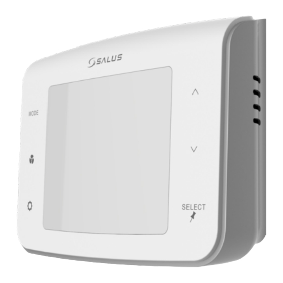
Low Voltage Fan Coil Thermostat ST101ZB Quick Start Guide For other language versions, please visit www.salusinc.com... - Page 2 Notices Please read these instructions carefully before installing and using the Low Voltage Fan Coil Thermostat. • Follow all local and electricity supplier regulations regarding the installation or replacement of a thermostat. An authorized, qualified installer may be required. • Do not connect any of the terminals to a 120/240 VAC supply. The Low Voltage Fan Coil Thermostat uses a 24 VAC power source.
-
Page 3: Let's Get Started
1. Let’s Get Started Make sure you have the following items: Thermostat with Wiring Labels Screws and Quick Start Guide Wiring Mount Anchors Tools: • #1 Phillips or flathead Optional Tools • Smartphone or digital camera to take picture screwdriver •... -
Page 4: Determine Wiring Configuration
2. Turn Off Power to the Fan Coil System This is usually accomplished by turning off the circuit breaker in the breaker panel. 3. Determine Wiring Configuration • Remove the old thermostat from the wall to expose the wiring terminals. •... - Page 5 Use the following table as reference: Terminal Function Name 4 pipe system 2 pipe system 24VAC input Common of AC input Hot water valve output Pipe valve output Chilled water valve output Auxiliary Heat (A) Fan coil low speed control Fan coil medium speed control Fan coil high speed control Accessory output (relay contact)
- Page 6 4. Remove Old Thermostat Terminals After all wires have been labeled, carefully remove the wiring and any mounting or back plate from the old thermostat. Tip: Wrap the wires around a pencil to prevent them from falling into the wall space Note: If you intend to paint the mounting surface, now is the best time to do so to insure complete wall coverage behind and around the...
- Page 7 5. Install Wiring Mount Remove the wiring mount from the packaging, and use the included wall screws and/or anchors to attach the wiring mount to the wall, making sure the wires run through the center opening. If alternate mounting holes are required, use a wall plate (sold separately).
-
Page 8: Attach Wiring
6. Attach Wiring Connect the labeled wires to their matching terminals based on the fan coil configuration as follows: Configuration 2-pipe Heat Only √ √ √ √ √ 2-pipe Cool Only √ √ √ √ √ 2-pipe Heat or Cool - √... - Page 9 7. Attach Thermostat to Wiring Mount Attach the thermostat to the wiring mount by aligning the connector pins and the plastic retention posts and pushing the thermostat onto the wiring mount. Make sure the connector pins are not bent and that the thermostat is fully seated on the wiring mount.
- Page 10 9. Pair Thermostat After powering up and initializing, the thermostat will display the pairing screen. Consult the pairing guide for your home automation system to determine how to add the Low Voltage Fan Coil Thermostat to your system. After pairing, the device will automatically enter Installer Mode to allow configuration of the device.
-
Page 11: Configuring The Thermostat
10. Configuring the Thermostat In Installer Mode, the buttons have the following function: Button Function SELECT Save displayed value for parameter and, short press go to next parameter (wrap around at end back to 0) long press (~2s) go to previous parameter (wrap at 0 to end of parameters) ‡... - Page 12 Parameter Name Values (default in bold) Heat/Cool For 2 Pipe: For 4 Pipe: Configuration 0 = Heat Only 1 = Cool Only 2 = Heat or Cool 2 = Heat or Cool Manual changeover Manual changeover 3 = Heat or Cool 3 = Heat, Cool or Auto Seasonal changeover changeover...
-
Page 13: Normal Operation
11. Normal Operation After exiting Installer Mode, the device will go to the Home Screen with the following button functions. Button Function MODE Select heat/cool/auto mode Select fan operating mode SETTINGS Enter/Exit User Settings Mode for the following user accessible settings: •... -
Page 14: Code Functions
12. Code Functions The device can perform additional functions required for certain situations. To access the functions, press the MODE, FAN, and SETTINGS buttons simultaneously C0dE until the screen appears (~2 seconds). Enter the code for the desired function from the table below, using the ‡... -
Page 15: Fcc And Industry Canada
13. FCC and Industry Canada This device complies with Part 15 of the FCC Rules. Operation is subject to the following two conditions: (1) this device may not cause harmful interference, and (2) this device must accept any interference received, including interference that may cause undesired operation. Changes or modifications to this unit not expressly approved by the party responsible for compliance could void the user’s authority to operate the equipment. -
Page 16: Warranty
No oral or written information or advice given by Salus or a Salus- authorized representative shall modify or extend this warranty. If any term is held to be illegal or unenforceable, the legality or enforceability of the remaining terms shall not be affected or impaired.
Need help?
Do you have a question about the ST101ZB and is the answer not in the manual?
Questions and answers
Thermostat is completely off. When I turn off fan coil and turn on, it displays “BOOT” for a second and screen goes off. I checked the wirings and all look good. What is the issue here? Does it have batteries somewhere? Thanks.
The Salus ST101ZB thermostat does not use batteries; it is powered through wiring from the fan coil system. If the thermostat is completely off and displays “BOOT” before turning off, the issue could be a power supply problem. This may be due to incorrect wiring, loose connections, or the fan coil system's circuit breaker being off. Check that power is properly supplied to the thermostat and verify the wiring configuration.
This answer is automatically generated
Take out schedule from thermostat
To remove the schedule from the Salus ST100ZB thermostat, change Parameter P00 to 0. This disables programmable mode, making the thermostat operate as a non-programmable device with no scheduling capability.
This answer is automatically generated