
Related Manuals for Salus ST620ROF


Summary of Contents for Salus ST620ROF
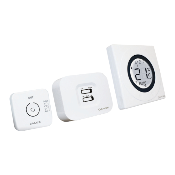
- Page 1 Programmable RF Room Thermostat with One Touch Energy Saving Override Control Instruction Manual Model: ST620ROF I N S T R U C T I O N M A N U A L...
-
Page 2: Product Compliance
R&TTE Directives 99/5/EC SAFETY INFORMATION These instructions are applicable to the Salus Controls model stated on the front cover of this manual only, and must not be used with any other make or model. These instructions are intended to apply in the United Kingdom only, and should be followed along with any other statutory obligations. - Page 3 The ST620ROF from Salus Controls is a stylish and accurate 5/2 or 7 day programmable electronic thermostat with a large, easy to read Liquid Crystal Display (LCD). This programmable thermostat has been specifically designed to be used Volt Free.
- Page 4 • Manual Time / Date Setting Option • Frost protection • Holiday Function • Large, easy to read display with blue backlight • Service Function • Burner on symbol • Easy to use programming • User friendly ST620ROF INSTRUCTION MANUAL...
-
Page 5: Installation
(such as radios, TV sets, computers, etc.), and is not mounted on or in close proximity to large metal objects. Installing the ST620 in enclosed areas such as cellars and basements is not recommended. ST620ROF INSTRUCTION MANUAL... - Page 6 / heating system supplier for advice on how to continue. The ST620ROF Receiver should be mounted in a suitable location that is both accessible for the connection of mains and control wiring, and allows good reception of the RF signal. The Receiver needs a 230V AC mains supply to operate, and this should be fused appropriately (16A max.).
- Page 7 Please note: These screws DO NOT need to be fully removed. Once the cover is fully removed the terminals will become exposed ready for installation. 230V Switching - Combination Boiler Volt Free - Combination Boiler BOILER BOILER BOILER BOILER 230V 230V 230V ST620ROF INSTRUCTION MANUAL...
- Page 8 You will now see the battery compartments on the rear of the front fascia as shown. Ensure that the batteries are inserted correctly and check the polarity. ST620ROF INSTRUCTION MANUAL...
- Page 9 Now put the ST620 front fascia in a safe place so you can mount the ST620 back plate. The back plate is easily fixed to the wall and uses industry standard mounting positions. We recommend that you continue with the back plate mounting before starting to program the ST620. ST620ROF INSTRUCTION MANUAL...
- Page 10 Mounting the Back plate Use the screws and anchors supplied to mount the ST620 back plate in your chosen position. Now attach the ST620 front fascia to the back plate. Remember to tighten the securing screw. ST620ROF INSTRUCTION MANUAL...
- Page 11 To begin installation remove the front cover by sliding it up from the back plate. Mark and drill two holes at points ‘A’. Fix the OTO back plate to the wall using the screws and anchors provided. ‘A’ ‘A’ ST620ROF INSTRUCTION MANUAL...
- Page 12 Insert the two AAA batteries (supplied) into the bottom rear of the front cover Position the front cover abovethe back plate and slide down until the cover is in line with back plate ST620ROF INSTRUCTION MANUAL...
- Page 13 SETTING UP RF COMUNICATION BETWEEN ST620ROF Press the SYNC button for 3 seconds then release, the bottom switch will become red. (SYNC Button). Activate ST620 into pairing mode. To access the Menu screens on the ST620RF, press the OK key twice. The first menu displayed is the PROGRAM menu:...
- Page 14 SETTING UP RF COMUNICATION BETWEEN ST620ROF Press the SYNC button for 3 seconds on the One Touch Overide and then release. (SYNC Button) Press the SYNC button for 3 seconds then release, the bottom switch will become red. (Note: Once paired, the bottom switch will turn green).
- Page 15 To deactivate the OTO press the button again, the or 6 °C setback temperature setting Lowest set temperature in the light will flash once and go out. ST620 is used (or manual override AUTO setpoint, or programme setting of that day) ST620ROF INSTRUCTION MANUAL...
-
Page 16: User Control Function
RCC indicator Indicates unit is searching for radio controlled clock signal Service indicator Indicates Service function is active Frost Mode indicator Indicates frost setting is turned on Touch Lock indicator Indicates touch lock is activated ST620ROF INSTRUCTION MANUAL... - Page 17 Single touch- sets the unit back 1 step. Hold for 2 seconds sets unit back to normal mode Reset Button Resets the thermostat to default (original factory) settings Slide Switch Activates and deactivates the key lock function (prevents accidental changes) ST620ROF INSTRUCTION MANUAL...
-
Page 18: Basic Operation
This will display the current set temperature. The set temperature will be displayed for two seconds before the LCD changes to display the room temperature again. The ST620 will go back to AUTO mode without changing the set temperature after 10 seconds of inactivity, or after pressing the Arrow key. ST620ROF INSTRUCTION MANUAL... -
Page 19: Manual Override
Manual Override mode is cancelled. Manual Override mode can be cancelled at any time by pressing and holding the Arrow key for 2 seconds – this will return the ST620 to AUTO mode. ST620ROF INSTRUCTION MANUAL... -
Page 20: Advanced Functions
Pressing the Arrow key will return the ST620 to AUTO/MANUAL mode. The programmable thermostat will also return to AUTO/MANUAL mode after 10 seconds if no Key is pressed. NOTE: SERVICE and CONTROL are functions that should be carried out by an installer or competent person. These function are explained in detail on Page 32. ST620ROF INSTRUCTION MANUAL... - Page 21 After correct selection of the day option, the ST620 display will change to the next programming screen. These screens allow you to set the required time and temperature settings to provide optimum control for your heating system. ST620ROF INSTRUCTION MANUAL...
- Page 22 Programme 1 (hour, minutes, and temperature). If you decide to enter settings for individual days rather than Weekdays or Weekends, the ST620 also offers a time saving COPY function that allows the user to copy settings from one day to another. ST620ROF INSTRUCTION MANUAL...
-
Page 23: Holiday Function
ST620 is in HOLIDAY mode the FROST protection mode will be disabled. When the holiday end date is reached, the HOLIDAY mode will be turned off automatically and the ST620 will operate in AUTO mode. The HOLIDAY mode indicator will be displayed on all the HOLIDAY menu screens. ST620ROF INSTRUCTION MANUAL... - Page 24 (‘S_YEAR’) – this is done in exactly the same way as previously described for the date and month. After confirming the year setting by pressing the OK key, the display will then change to display the first screen for entering the holiday end date. ST620ROF INSTRUCTION MANUAL...
- Page 25 MANUAL or AUTO indication. Pressing the Touch Ring will change the display to show the current temperature setting, but this setting cannot be adjusted while in this mode. ST620ROF INSTRUCTION MANUAL...
-
Page 26: Frost (Protection) Function
Entering the FROST menu allows you to turn the frost protection mode of the ST620 on or off. The FROST mode temperature is preset at 5 ºC; this temperature is factory set and cannot be adjusted. The FROST mode indicator will be displayed on all the FROST menu screens. ST620ROF INSTRUCTION MANUAL... -
Page 27: Sleep Function
Pressing the Touch Ring for 1 second will turn on the LCD backlight, and pressing the Touch Ring for 3 seconds will wake the ST620 from SLEEP mode and restore the programmable thermostat to AUTO mode. NOTE: The unit will not control the heating while in SLEEP mode. ST620ROF INSTRUCTION MANUAL... - Page 28 If the time and date setting need to be set manually, this can be done by accessing the TIME menu. The first option within the menu is a choice of 12 or 24 hour clock setting. ST620ROF INSTRUCTION MANUAL...
- Page 29 – change this setting in the same way using the Touch Ring, and confirm the setting using the OK button. After setting the time, the next screen display allows you to set the date – this is set in exactly the same way as previously described for the time. ST620ROF INSTRUCTION MANUAL...
-
Page 30: Language Function
This is explained on page 7. However if you require to change the language of the ST620 then you can do this by accessing the language menu. Entering the language menu will allow you select your required language. ST620ROF INSTRUCTION MANUAL... - Page 31 Once you have displayed your required language, press the OK button to select and save. ST620ROF INSTRUCTION MANUAL...
-
Page 32: Service Function
SERVICE menu screens. Firstly you need to enter a unique PIN code, when the first digit flashes scroll to set the first digit and press OK to confirm the repeat for the other two digits. ST620ROF INSTRUCTION MANUAL... - Page 33 Once all digits have been entered, press OK to confirm or the arrow key to return to previous digit or previous display. The service code is total 3 digits, from 000 to 999. NOTE: If you forget the code then you will need to contact the Salus Technical Team Now you have entered your own PIN code you will be asked to select SERVICE ON or OFF.
- Page 34 If you have selected service as ON then follow the instructions on the next pages. The next menu screen allows you to set the next service date for the system. Set the date in the order of; day, month and year: ST620ROF INSTRUCTION MANUAL...
- Page 35 Once set as described, the SERVICE indicator will appear on the display 30 days before the set date. At seven days before the set date, the SERVICE indicator will flash and the bottom section of the display will alternate between displaying the current mode (AUTO or MANUAL), and the telephone number previously entered. ST620ROF INSTRUCTION MANUAL...
- Page 36 ST620ROF INSTRUCTION MANUAL...
- Page 37 (ON/OFF or PWM control), and confirm the choice using the OK button. Use the Arrow key to return to the Menu Option display. PWM mode should only be selected by the Engineer carrying out the installation or other qualified person. ST620ROF INSTRUCTION MANUAL...
-
Page 38: Useful Information
Clock, Programme or Temporary Override modes – in this case, the backlight will remain illuminated for 10 seconds after the last key press. The backlight will not illuminate if the ST620 battery is low, or if the Slide Switch is in the LOCKED position. ST620ROF INSTRUCTION MANUAL... -
Page 39: Slide Switch
Boiler Control will turn off the boiler, and the LED indicator will flash constantly (two times every second). Once the Boiler Control receives a valid ON or OFF signal, the Boiler Control will control the heating system accordingly. ST620ROF INSTRUCTION MANUAL... -
Page 40: Auto Mode
Manual Mode the Receiver can still receive the RF signal from the Control Centre and once the user switches to Auto Mode, the output relay will be controlled to turn on or turn off automatically once more. ST620ROF INSTRUCTION MANUAL... -
Page 41: Maintenance
(please DO NOT use solvents, polishes, detergents or abrasive cleaners, as these can damage the thermostat). There are no user serviceable parts within the unit; any servicing or repairs should only be carried out by Salus Controls or their appointed agents. - Page 42 Environment Operating Temperature: 0 ºC to + 50 ºC Storage Temperature: - 10 ºC to + 60 ºC Switching Switching Voltage: 0 - 230V AC / 50Hz Switching Current: 16A resistive, 5A inductive Contact Type: Volt Free ST620ROF INSTRUCTION MANUAL...
- Page 43 ST620WBC Warranty Salus Controls warrants that this product will be free from any defect in materials or workmanship, and shall perform in accordance with its specification, for a period of two years from the date of installation. Salus Controls sole liability for breach of this warranty will be (at its option) to repair or replace the defective product.
- Page 44 E: tech@salus-tech.com www.salus-controls.com SALUS Controls is a member of the Computime Group Maintaining a policy of continuous product development SALUS Controls plc reserve the right to change specification, design and materials of products listed in this brochure without prior notice.
Need help?
Do you have a question about the ST620ROF and is the answer not in the manual?
Questions and answers