
Related Manuals for Watson-Marlow MasoSine EC 25


Summary of Contents for Watson-Marlow MasoSine EC 25
- Page 1 Manual - Technical Documentation ATEX Watson-Marlow MasoSine - Pumps EC 25 / EC 40 / EC 60 Revision 4.4 / November 2010...
-
Page 2: Table Of Contents
Content Technical datasheet............................4 GENERAL ......................5 PURPOSE ......................5 FUNCTIONING PRINCIPLE................. 5 SAFETY INSTRUCTIONS..................5 Basic safety instructions........................5 Safety symbols ...........................5 Obligation of the operator........................5 Organizational measures ........................5 Obligation of the personnel .........................6 Training of the personnel ........................6 Informal safety measures........................6 Dangers when handling the machine....................6 Safety measures in normal operation ....................6 4.10... - Page 3 CHANGING THE CONNECTION POSITION..........11 CHANGING THE DIRECTION OF ROTATION..........11 IMPORTANT: OBSERVE BEFORE START-UP!..........11 CLEANING ...................... 12 14.1 Cleaning in own circuit with water, alkali, acid ..................12 14.2 Cleaning in the CIP circuit.........................12 14.3 Manual cleaning ..........................12 14.4 Sterilization............................12 OIL CHANGE ....................
-
Page 4: Technical Datasheet
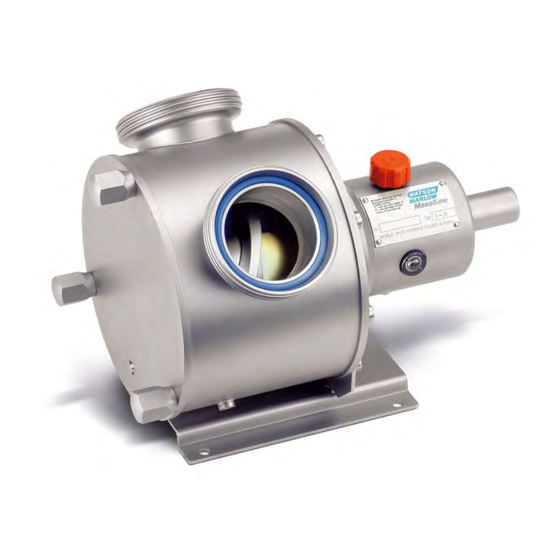
Technical datasheet Please remove all technical information from the technical Data Sheet. For spare parts ordering refer to software component list. If you have problems to identify parts, please refer the drawing and parts list. In case of any questions please contact the Technical Support Revision 4.4 / November 2010... -
Page 5: General
Always consult the manufacturer before any changes are to be made to the pump, its components or application. Functioning principle The functioning principle of the Watson-Marlow MasoSine Pump is ingeniously simple. The pump consists of modular components to allow for easy assembly, disassembly and in-line maintenance, preventing the need to return the pump for factory repair. -
Page 6: Obligation Of The Personnel
Dangers when handling the machine The Watson-Marlow MasoSine Pump is built according to the state of the art and the recognized safety engineering rules at the time of manufacture. Danger to life and limb of the user or other persons or impairments to the machine or to other assets can arise if safety instructions are not followed. -
Page 7: Constructional Changes To The Machine
Use only original MASO-Sine parts. Use of parts not supplied by MASO-Sine or other aftermarket parts will void all warranties. Aftermarket parts are not authorized by Watson-Marlow MasoSine and void all certifications such as 3-A, USDA and FDA. -
Page 8: Zone Classification
A distinction is made between dust and gas explosive atmospheres. In the model code, the atmosphere is abbreviated with G (Gas) and D (Dust). Watson-Marlow MasoSine - Pumps are only designed for the explosive atmospheres G (Gas) and D (Dust)! Ignition protection Our pumps are subject to ignition protection "c"... -
Page 9: Maintenance / Repair
Incorrectly performed repairs Cases of catastrophe due to effect of foreign bodies and acts of God. Watson-Marlow MasoSine grants no warranty on this documentation as well as no implicit warranties on commercially customary quality and suitability for a certain application. -
Page 10: Installation
Installation The motor shaft and pump shaft connection must be protected against contact! DO NOT LET RUN THE PUMP WITHOUT COUPLING GUARD! Place the pump on a level ground. Do not start without the protection against contact!! The foundation should be dimensioned sufficiently for the weight of the pump. There should be sufficient space for maintenance work around the pump. -
Page 11: Changing The Connection Position
11 Changing the connection position The standard nozzle configuration is set at the 10-2 position from the factory. To change the nozzle position, all internal parts must first be Pos. 10 removed as in illustration 001. Remove the screw, Pos. 30, as well as the screws Pos.9 (2 pcs.). -
Page 12: Cleaning
Cavitation destroys the pump. 14 Cleaning All Watson-Marlow MasoSine Pumps are fully capable of CIP cleaning. Please observe our CIP cleaning regulations. 14.1 Cleaning in own circuit with water, alkali, acid 1. Set control gear to maximum speed (at least 400 rpm). -
Page 13: Oil Change
Only Watson-Marlow MasoSine spare parts may be used. Watson-Marlow MasoSine... -
Page 14: Troubleshooting
Inserted closed gate valve Check pipe system Pump is noisy Noises come from the drive / pump Consult Watson-Marlow MasoSine Suction pipe too small (cavitation) Shorten suction pipe or increase diameter, reduce speed Knocking noises from the pump head Scrapergate wear... -
Page 15: Adjusting Dimension
20 Adjusting dimension For the pumps of the series EC 25 / EC 40 / EC 60 Laminum-Ring Pump type Adjusting dimension X 53.00 mm ±0.05 EC 25 2.087” ±.002 74.90 mm ±0.05 EC 40 2.949” ±.002 120.75 mm ±0.05 EC 60 4.754”... -
Page 16: Tightening Torques
21 Tightening torques WATSON-MARLOW MASOSINE PUMP EC 25 10 N•m Flange - Bearing Housing M6 DIN 7984 7 lb•ft 25 N•m Flange - Pump Housing M8 DIN 931 18 lb•ft 25 N•m Adapter Plate - Pump Housing M8 DIN 933 18 lb•ft... -
Page 17: Dismantling
22 Dismantling Remove the Front Cover to the front Before the work starts, the shaft has to be fixed against movement Remove the Liner, front Remove Cap Nuts / Wing Nuts (RIGHT-HAND thread) Compare the tool kit illustration Revision 4.4 / November 2010... - Page 18 Remove the Rotor-Assembly, consisting of Rotor, Scraper and Guide Rail Loosen and remove the Shaft Nut Revision 4.4 / November 2010...
-
Page 19: Dismantling „Lip Seal System
23 Dismantling „Lip Seal System“ The nose of the tool has to be hooked in the groove of the Liner The Liner, back consists of the Lip Seal System Remove the Shaft Sleeve Take off the Lip Seals and Lip Seal Support Rings for exchanging Remove the Liner, back with the aid of tool kit Revision 4.4 / November 2010... -
Page 20: Dismantling „Mechanical Seal System
24 Dismantling „Mechanical Seal System“ The nose of the tool has to be hooked in the groove of the Liner The Liner, back consists of the Mechanical Seal System Face, static Remove the Dynamic Ring Holder together with Face, dynamic Remove carefully the Face, static Remove the Liner, back with aid of tool kit Revision 4.4 / November 2010... -
Page 21: Assembly
25 Assembly The assembly has to be done in the same instruction order as the disassembly. 25.1 Assembly „Rotor-Assembly“ During mounting Rotor-Assembly the noses of the Guide rail mustn’t laid on the surface of the Rotor. To achieve this you have to fit Scraper and Guide rail in a position that the noses of the Guide rail... -
Page 22: Pump Sizes
26 Pump sizes 26.1 Cross section drawing EC 25 with Lip Seal System 26.2 Cross section drawing EC 25 Mechanical Seal System Revision 4.4 / November 2010... -
Page 23: Cross Section Drawing Ec 40 With Lip Seal System
26.3 Cross section drawing EC 40 with Lip Seal System 26.4 Cross section drawing EC 40 with Mechanical Seal System Revision 4.4 / November 2010... -
Page 24: Cross Section Drawing Ec 60 With Lip Seal System
26.5 Cross section drawing EC 60 with Lip Seal System 26.6 Cross section drawing EC 60 with Mechanical Seal System Revision 4.4 / November 2010... -
Page 25: Parts List For An Ec 25 / Ec 40 / Ec 60 Pump
26.7 Parts list for an EC 25 / EC 40 / EC 60 Pump No. Qty. Item Description No. Qty. Item Description XX-1610-ZZ Cap Nut EC 25 XX-1400-ZZ Bearing Housing XX-1600-ZZ Wing Nut EC 25 XX-3101-ZZ Lip Seal, Outboard XX-1610-ZZ Cap Nut EC 40 XX-3702-ZZ Shaft Key XX-1600-ZZ Wing Nut EC 40 XX-1000-ZZ Shaft... -
Page 26: Code-Structure For Spare Part Orders
27 Code-Structure for spare part orders Structure of the article number: xx-yyyy-zz Type of pump Part number Code of material 1. Type of pump code pump size EC 25 EC 60 EC 40 2. Part numbers: Please see attached technical data sheet. 3. -
Page 27: Dimensional Drawings
28 Dimensional drawings 28.1 Dimension table for pump with German Milk Fittings Fittings EC 25 9.25 11.42 1.38 13.35 7.28 6.11 0.59 2.05 3.46 1.27 NW 65 32,2 NW 65 EC 40 11.65 15.04 1.38 16.97 7.87 6.69 0.79 1.97 5.12 1.19 NW 100... -
Page 28: Dimension Table For Pump With Tri-Clamp (Tc)
28.2 Dimension table for pump with TRI-CLAMP (TC) Fittings EC 25 9.25 11.42 1.38 13.35 7.28 6.11 0.59 2.05 3.46 1.27 TC 2,5" 32,2 TC 2,5" EC 40 11.65 15.04 1.38 16.97 7.87 6.69 0.79 1.97 5.12 1.19 TC 4" 30,2 TC 4"...
Need help?
Do you have a question about the MasoSine EC 25 and is the answer not in the manual?
Questions and answers