Oki MC360 MFP User Manual
Mc360 mfp user's guide (english)
Hide thumbs
Also See for MC360 MFP:
- Manual do usuário (158 pages) ,
- Guía del usuario (156 pages) ,
- Manual de l'utilisateur (146 pages)
Table of Contents
Advertisement
Quick Links
Advertisement
Table of Contents

Related Manuals for Oki MC360 MFP


Summary of Contents for Oki MC360 MFP
- Page 1 MC360 MFP User’s Guide 59318902 my.okidata.com...
-
Page 2: Copyright Information
Copyright Information Copyright © 2009 by Oki Data. All Rights Reserved Document Information ________________________________ MC360 MFP User’s Guide P/N 59318901 Revision 1.1 October, 2009 Disclaimer__________________________________________ Every effort has been made to ensure that the information in this document is complete, accurate, and up-to-date. The manufacturer assumes no responsibility for the results of errors beyond its control. -
Page 3: Table Of Contents
ONTENTS Emergency First Aid ......6 Notes, Cautions and Warnings ....7 Introduction . - Page 4 Menu Structure ......44 Copy function......45 Scan/Scan to function .
- Page 5 Installing additional memory ....127 Memory upgrade ......127 Checking the Memory status .
-
Page 6: Emergency First Aid
MERGENCY IRST Take care with toner powder: diagline_symbol.jpg If swallowed, induce vomiting and seek medical attention. Never attempt to induce vomiting if person is unconscious. If inhaled, move the person to an open area for fresh air. Seek medical attention. If it gets into the eyes, flush with large amounts of water for at least 15 minutes keeping eyelids open. -
Page 7: Notes, Cautions And Warnings
OTES AUTIONS AND ARNINGS NOTE A note provides additional information to supplement the main text. CAUTION! A caution provides additional information which, if ignored, may result in equipment malfunction or damage. WARNING! A warning provides additional information which, if ignored, may result in a risk of personal injury. For the protection of your product, and in order to ensure that you benefit from its full functionality, this model has been designed to operate only with genuine Oki Printing Solutions... -
Page 8: Introduction > 8
NTRODUCTION Congratulations on choosing this Multi Function Product (MFP). It has been designed with advanced features, to give you clear, vibrant color prints and crisp black and white pages at high speed, on a range of office print media. With this MFP, you can instantly scan paper-based documents and deliver the electronic image to various destinations including email addresses, printers, ftp servers, facsimile machines, USB memory stick, or someone else's computer on the network. - Page 9 > Single Pass Color Digital LED technology for high speed processing of your printed pages. > High speed USB 2.0 interface. > 10Base-T and 100Base-TX network connection lets you share this resource among users on your office network. > Scan to E-mail - Connected to an Ethernet network and a SMTP server, this MFP allows you to transmit document(s) over the internet via e-mail.
-
Page 10: Mfp Overview
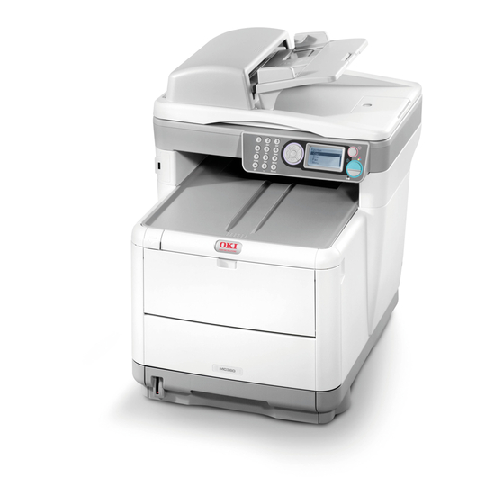
The following optional feature is available: > 256MB additional memory, to allow the printing of more complex pages. OVERVIEW RONT VIEW Front 3 quarter lt.jpg 1. Scanner bed. 6. Output stacker, face down. Standard printed copy delivery point. Holds up to 150 sheets of 21.3 lb (80 g/m²). -
Page 11: Rear View
EAR VIEW This view shows the connection panel and the rear output stacker. Rear 3 quarter rt + panel.jpg 1. USB connection. 5. IEC (CE22) AC power connection. 2. Local Area Network 6. AC Power ON/OFF switch. connection. 3. Local Telephone handset Automatic Document Feeder (ADF). -
Page 12: The Operator Panel
PERATOR ANEL Operator panel.jpg 1. Ten Key Pad Used to enter numbers, upper-case/lower-case letters and symbols in the Entry Line. 2. LEFT key When in switching Mode: Returns the display to the Function Selection screen or Scan Sub Function Selection screen from the Stand-by screen. When Setting up: Increments the value of the tree structure. - Page 13 Operator panel.jpg 6. RIGHT Key When in switching Mode: Used to confirm the Mode selected. Used to start Push Scan (If Push Scan is selected, the Executing Push Scan screen appears). When Setting up: Decrements the value of the tree structure. Increments the value of the tree structure as the set value is confirmed.
-
Page 14: Languages Supported
ANGUAGES UPPORTED English German French Italian Spanish Swedish Norwegian Danish Dutch Portuguese Greek Brazilian Portuguese Russian Polish Turkish Czech Hungarian Finnish NOTES: 1. This list is not exhaustive or conclusive. 2. See the information enclosed with the product (the Panel Language Setup utility) on the procedure for changing the language setting. -
Page 15: Getting Started
ETTING TARTED NSTALLING DRIVERS AND TILITIES NOTE: You must be logged on as an administrator or a member of the Administrators group in order to complete this procedure. If your computer is connected to a network, network policy settings may also prevent you from completing this procedure. - Page 16 If CD autoboots, cancel the dialogue. The ‘New Hardware Found' dialogue will appear on the screen FNHW Wizard 1.jpg If you do not see the ‘New Hardware Found' dialogue, please check that power and USB cables are connected properly, and the printer is switched on. Install Twain driver first FNHW Wizard 2.jpg MC360 MFP User’s Guide...
-
Page 17: Fax Printer Driver
(“Pull Scan”). Installation of the hotkey utility is optional. It can be downloaded from the Oki Data web site, http://www.okiprintingsolutins.com. Information on using the hotkey utility can be found in “Scan to PC option” on page 75. - Page 18 Setting up the Hotkey Utility Install the hotkey utility: Set-up will place a “hotkey” icon on your desktop. Double-click this icon to open the hotkey console. console.jpg Select Settings. The following screen will appear. Hotkey settings.jpg Select the function you want to set in section (1). Set the parameters for this function in section (2).
-
Page 19: Mfp Setup Tool
MFP S ETUP TOOL Installation of the MFP setup utility is optional and can be found on the Driver/Utilities CD under the Utilities folder. The setup program does not automatically place an icon on your desktop. If you wish, you can drag and drop this icon on to your desktop for ease of future use The MFP setup tool can discover device over USB or network connections. - Page 20 MFP setting.jpg MFP Settings: Allows you to change most of the same settings as you'd see on the MFP's operator panel, on a locally connected PC. The settings include an Admin. menu. This is password protected and hidden by default. To enable the Admin menu, select: Setting>MFP Setting>Display >...
- Page 21 Phone Book Manager: For managing people and fax numbers (for "scan to fax" feature of MFP). Add names, fax numbers, assign them to speed dial numbers. MFP setting4.jpg > Arrange people into groups. > Import and export settings to CSV files. >...
-
Page 22: Scanner/Copier Section
such as whether they can copy, print, scan to email, scan to network PC or fax. MFP setting6.jpg > Import and export settings to CSV files. > Import settings from other Oki MFP devices. CANNER COPIER ECTION The MFP can scan/copy/send document(s) either using the ADF (Automatic Document Feeder) or manually on the glass. -
Page 23: Printer Section
RINTER SECTION APER RECOMMENDATIONS Your MFP will handle a variety of print media, including a range of paper weights and sizes. This section provides general advice on choice of media, and explains how to use each type. The best performance will be obtained when using standard 20 ~24 lb. -
Page 24: Cassette Tray
Banner Paper ® > 52206002 (100 count) 8.5 x 35.4 inches (215.90 x 899.16 mm) ® SynFlex Paper > 8.5 x 11 inches (215.90 x 279.40 mm) > Waterproof and Tear-resistant ASSETTE TRAY The Cassette Tray can handle paper weights of 17.1 to 46.9 lb. (64 g/m²... -
Page 25: Multi Purpose Tray
ULTI PURPOSE TRAY The multi purpose tray can handle the same media sizes as the cassette trays but in weights of 20 - 54.1 lb (75 g/m² to 203 g/m²). For very heavy paper stock, use the face up (rear) paper stacker. -
Page 26: Face Down Stacker
ACE DOWN STACKER The face down stacker on the top of the printer can hold up to 150 sheets of 21.3 lb (80 g/m²) standard paper and can handle paper stocks up to 32 lb. (120 g/m²). Pages printed in reading order (page 1 first) will be sorted in reading order (last page on top, facing down). -
Page 27: The Printer
separated, then tap the edges of the stack on a flat surface to make it flush again (c). Paper riffle.jpg Load the tray with paper. Use the level indicators (a and b) as a guide. For letterhead paper load face down with top edge towards the front of the printer. - Page 28 Adjust the rear stopper (a) and paper guides (b) to the size of paper being used. A6 paper uses area (c). Paper guide adjust.jpg If you are using A6 paper, re-position the rear paper guide to the front slot. Rear guide - A6.jpg MC360 MFP User’s Guide Getting Started >...
- Page 29 Close the cassette tray gently. NOTE: To prevent paper jams: > Do not leave space between the paper and the guides and rear stopper. > Do not overfill the paper tray. Capacity depends on the type of paper stock. > Do not load damaged paper.
- Page 30 is stacked in reverse order and tray capacity is approximately 10 sheets, depending on paper weight. Always use the face up (rear) Stacker for heavy paper (card stock etc.). CAUTION! Do not open or close the rear paper exit while printing as it may result in a paper jam.
-
Page 31: Multi Purpose Tray
ULTI PURPOSE TRAY The Multipurpose tray is used for printing on media such as envelopes, non-standard media, A5, A6, and heavyweight paper (see “Multi purpose tray” on page 25). Open the multi purpose tray. MPT tray open.jpg Adjust the Paper Guides (a) to the size of paper you are going to print on, using the markings on the Paper Platform. - Page 32 Position a sheet of paper on the Paper Platform so that it is gripped in place. MPT tray paper in.jpg > Load your chosen media one sheet at a time. > When printing on letterhead paper, load the paper into the Multi Purpose Tray with pre-printed side up and top edge into the printer.
-
Page 33: Configuring Your Machine
ONFIGURING YOUR MACHINE ENERAL Before using this MFP, a few basic settings have to be carried out. Ensure that you have the relevant permission/PIN numbers before commencing. The Factory set default passwords/PIN are: Administrator aaaaaa 000000 Network (web page) last 6 figures of MAC address ECEIVING This MFP’s fax will automatically answer the telephone after the Ring Response delay. -
Page 34: Setting The Date & Time (Clock Adjustment)
& T ETTING THE LOCK DJUSTMENT The Date & Time can be set up by accessing the set up screen as follows: Using the Up or Down arrow keys, select the Menu function. Using the Right arrow key, select the Admin Menu. Enter a password when prompted (Default is “aaaaaa”). -
Page 35: Local Phone No
Using the Down arrow key scroll to Basic Setup. Press Enter. Using the Down arrow key scroll to Country Code. Press Enter. Select the Country in which the MFP is situated. Press Enter. Use Left arrow key to return to Function screen. OCAL HONE Set your local phone number as follows:... -
Page 36: Ring Response
At this point you will need the Administrator’s password) Enter the Admin password using the Ten Key Pad. Press Done to complete. Using the Down arrow key scroll to Fax Setup. Press Enter. Using the Down arrow key scroll to Basic Setup. Press Enter. -
Page 37: Access Control
CCESS ONTROL The operation and functionality of this machine can be limited to authorized personnel only by the simple introduction of a 4-9 digit PIN (Personal Identification Number). This is known as Access Control. The greater the number of digits in the PIN, the more secure it is. -
Page 38: Logout Operation
User PIN ID This is PIN ID for general users. If a PIN ID is registered as a general user, the function selection screen is displayed, also after PIN ID entry the function selection screen is displayed. Invalid PIN ID If the PIN number entered is invalid, Incorrect Password is displayed for 3 seconds and the display reverts to the Enter PIN ID screen. -
Page 39: The Scanner/Copier Section
CANNER OPIER SECTION INIMUM ONFIGURATION EQUIREMENTS To make the best of this MFP, the following configuration is required: To send Faxes: > A PSTN telephone line connection. To send e-mails: > TCP/IP network. > A SMTP and an optional POP3 server. >... -
Page 40: Subnet Mask
Explanation: DHCP Enable: Choose Yes to obtain IP/subnet/gateway addresses automatically from DHCP server. NOTE: With DHCP (Dynamic Host Configuration Protocol), a host can automatically be given a unique IP address each time it connects to a network making IP address management an easier task for network administrators. -
Page 41: Smtp Server
SMTP Server: NOTE: SMTP: (Simple Mail Transfer Protocol) is the main communication protocol used to send and receive e-mail on the Internet. This is the IP address of your SMTP Mail Server assigned by your network administrator. SMTP Port: The port number of your SMTP Mail Server. DNS server: NOTE: DNS: (Domain Name System). - Page 42 Scan to E-mail The MFP allows you to deliver your scanned document to e-mail addresses on the network. The document is first scanned and converted to a standard PDF, JPEG, TIFF, or MTIF (Multi-page TIFF) file format and then transmitted to remote recipients simultaneously as an e-mail attachment.
- Page 43 When a number is entered from the Ten Key pad, the number currently displayed is cleared and the number just entered is displayed as the first digit. When another number is entered, the number in the first digit moves to the next, and so on.
-
Page 44: Menu Structure
TRUCTURE The Main Menu has four top-level functions: Copy (see Table 1, “Copy Function,” on page 45) Scan (see Table 2, “Scan Function/Email,” on page 46, Table 3, “Scan Function/USB Memory,” on page 47, Table 4, “Scan Function/Network PC,” on page 48, and Table 5, “Scan Function/PC,”... -
Page 45: Copy Function
OPY FUNCTION This is the default mode on Power up, with Access Control disabled. Use the Down arrow key to select other functions and Enter to select an option. Default option (if relevant) is in bold text. Table 1: Copy Function LEVEL 2 DESCRIPTION OPTIONS... -
Page 46: Scan/Scan To Function
CAN TO FUNCTION Use the Down arrow key to select this function and Enter to select an option. Note that for each scan function, the scanned format (PDF, TIF, JPEG for color and PDF or TIF for B&W) is set in this menu path: Menu—>Scanner Menu—>{Type of Scan}—>Color Format &... -
Page 47: Usb Memory
Table 2: Scan Function/Email LEVEL 2 DESCRIPTION OPTIONS File Name A file name should be entered for Type the File Name the scanned images. This file name can be entered in Key Pad Mode. Up to 64 characters can be entered as text, except for the following;... -
Page 48: Network Pc
ETWORK NOTE: The MFP must be connected to a Network server to enable Scan to Network PC to be set up. Table 4: Scan Function/Network PC LEVEL 2 DESCRIPTION OPTIONS Profile Used to select the file server setting. Registered server setting The file server setting can be set from Web Page and Set-up Utility. -
Page 49: Fax Function
AX FUNCTION Table 6: Fax Function LEVEL 2 DESCRIPTION OPTIONS Check Dest. Displays the current fax number or — numbers (if any). Fax. no Enter the fax number(s) using the Ten Key Type a fax number pad. and press Enter to display the Continue menu. -
Page 50: Menu Function
ENU FUNCTION Table 7: Menu Function LEVEL 2 ITEM DESCRIPTION/OPTION View Information Print count Color pages Displays the total number of color pages printed Monochrome pages Displays the total number of mono pages printed Tray 1 Displays the total number of pages printed from the paper cassette tray Manual Feeder... - Page 51 Table 7: Menu Function LEVEL 2 ITEM DESCRIPTION/OPTION Supplies Life Cyan Toner The amount of toner remaining as a percentage (%). Magenta Toner “(#.#K)” is the capacity of the Yellow Toner toner cartridges installed in the Black Toner printer. Cyan Drum The remaining life of the drum as a percentage (%).
-
Page 52: Print Information
Table 7: Menu Function LEVEL 2 ITEM DESCRIPTION/OPTION Print Information Configuration Execute Prints out a report of the machine’s configuration Network Execute Prints out a report of the Network Information configuration Demo Page DEMO1 - Execute Prints a Demonstration page MFP Usage Execute - Copies (set) Prints a full report of the machine... - Page 53 Table 7: Menu Function LEVEL 2 ITEM DESCRIPTION/OPTION System Report Full Print On/Off Setup Panel Contrast –10 / 0 / +10 (continued) (for Operator’s panel) Network TCP/IP Enable/Disable TCP/IP protocol Setup IP Address Set Auto/Manual IP Address Set the IP Address Subnet Mask Set the Subnet Mask Gateway Address...
- Page 54 Table 7: Menu Function LEVEL 2 ITEM DESCRIPTION/OPTION Scanner Job Build Scanning On (turn On when two or more Setup pages need to be scanned on flatbed for the same scan file) / Off Email Setup Add “To” Address: On (selected “To”...
- Page 55 Table 7: Menu Function LEVEL 2 ITEM DESCRIPTION/OPTION LDAP Server Server Settings LDAP Server: Enter an IP Address Setup or Server Name for this LDAP server Port Number: Port Number for this LDAP Server Timeout: specify a Timeout value from 10 to 120 seconds Max.
- Page 56 Table 7: Menu Function LEVEL 2 ITEM DESCRIPTION/OPTION Fax Setup Clock Adjustment User ID <enter>, Password<enter> (advance with right arrow key) Basic Setup Service Bit: On (enables all the fax settings)/Off Country Code: select your country Local Phone No.: enter your local # Sender ID: enter up to 32 characters MCF (Single Location): On/Off...
- Page 57 Table 7: Menu Function LEVEL 2 ITEM DESCRIPTION/OPTION Fax Setup Basic Setup Ring Response: (the time from “Ring coming” to “Line catching,” (continued) (continued) select) 1 ring/ 5/10/15/20 seconds Monitor Control: Off/Type1/Type2 Speaker Volume: Off/Low/Middle/ High Soft Ringer Volume: (volume of ringer in Tel/Fax mode) Off/Low/ Middle/High No CED (called station...
- Page 58 Table 7: Menu Function LEVEL 2 ITEM DESCRIPTION/OPTION Printer Menu Tray Manual feed On/Off Configuration Tray 1 Config Paper Size: A4/A5/A6/B5/Legal 14/ Legal 13.5/Legal 13/Letter/ Executive/Custom Media Type: Plain/Letterhead/ Bond/Recycled/Rough/Glossy Media Weight: Light/Medium/ Heavy Manual Feeder Config Paper Size: A4/A5/A6/B5/Legal 14/ Legal 13.5/Legal 13/Letter/ Executive/Custom/Com-9 Envelope/Com-10 Envelope/...
- Page 59 Table 7: Menu Function LEVEL 2 ITEM DESCRIPTION/OPTION Copy Menu Copies 1-99 Reduce/Enlarge A4–>A5 Leg–>Let A4–>B5 Fit to Page 100% B5–>A4 Let–>Leg A5–>A4 Mode Mixed Photo Hi-Res Mixed Hi-Res Photo Density –3/–2/–1/0/+1/+2/+3 Input Tray Tray1/Manual Feeder Collate On/Off N-up 1in1/2in1/4in1(Hor.)/4in1(Ver.) Edge Erase 0.00/0.25/0.50/0.75/1.00 in 0/6/13/19/25 mm...
- Page 60 Table 7: Menu Function LEVEL 2 ITEM DESCRIPTION/OPTION Scan to Email B/W Format Grayscale: On/Off (continued) File Format - PDF/TIFF Grayscale Off: PDF/TIFF Grayscale On: PDF/TIFF/JPEG Compression Rate - Grayscale Off: G3/G4/Raw Grayscale On: Low, Medium, High, Raw (TIFF only) Resolution - Grayscale Off: 100/150/200/300/ 400/600 dpi...
- Page 61 Table 7: Menu Function LEVEL 2 ITEM DESCRIPTION/OPTION Calibration Auto Density Mode Auto/Manual Adjust Density Execute Adjust Registration Execute Cyan Reg. Fine Adjust –3/–2/–1/0/+1/+2/+3 Magenta Reg. Fine Adjust –3/–2/–1/0/+1/+2/+3 Yellow Reg. Fine Adjust –3/–2/–1/0/+1/+2/+3 System Executes shutdown Execute Shutdown procedure MC360 MFP User’s Guide Menu Structure >...
-
Page 62: Operation
PERATION With its intuitive control panel, this Multi Function Product (MFP) is designed to be easy to use. NOTE: If Access Control has been enabled, you will first have to enter your Password/PIN OADING OCUMENT FOR COPYING The MFP can scan/copy/send document(s) either from the ADF (Automatic Document Feeder) or on the glass. -
Page 63: Placing Document(S) In The Adf
> Keep the glass clean and without any documents left on it. NOTE: To transmit irregular types of document(s), place the document(s) on the glass or make a copy first and then transmit the copy instead. LACING OCUMENT IN THE Make sure document(s) are free of staples, paper clips and not torn. -
Page 64: Placing Document(S) On The Glass
LACING OCUMENT ON THE LASS Open the document cover. Place your document with the text face DOWN on the glass and align it to the upper-left corner. On-glass.jpg Close the document cover. You can make a single copy of a document, either from the ADF or from on the glass by pressing the mono or color button on the operator panel. - Page 65 to a percentage in increments of 1% by using the Custom (25%~400%) setting. Paper Size: Select from: Legal, Letter, A4, A5, B5. Image Quality: Select from Mixed, Photo, HiRes. Mixed, HiRes. Photo. Density: Sets scan density: –3, –2, –1, 0, +1, +2, +3 Input tray: Select which paper tray you are using, Tray 1, Manual Feeder.
- Page 66 Margin shift - right: This sets the amount to shift the document image to the right. NOTE: Any parts of the image that do not fit on the paper as a result of this setting, are not printed. The setting displayed, mm or inch, depends on the setting in Admin Setup - System Setup - Unit of Measure in Menu Mode.
-
Page 67: Operation
PERATION Place your document(s) with the text face Up in the ADF or face Down on the glass (as described above). If you wish to make one copy of the document(s), simply press the Start button (monochrome or color option). If more than one copy is needed, first set the number of copies by pressing the Enter button and setting the number of copies required (1-99). -
Page 68: Scan To E-Mail Option
CAN TO MAIL OPTION From the next drop-down menu, select the Destination field, and enter the destination e-mail address. This can be entered in several ways. From the Address Book - by selecting Address Book on the next drop-down menu. Use the up and down arrows on the control panel to select multiple e-mail addresses and press the Enter key for each. - Page 69 When you have finished entering all your e-mail addresses, select Done instead of Continue. The screen will ask you to Confirm your selection. Selecting address from a Network Selecting from a Network allows you to search Email Addresses from a Lightweight Directory Access Protocol (LDAP) Server.
- Page 70 Adding a new Email Address: Move the cursor to the Address Book and press the Right or Enter key to display the Email Address/ Group Address Selection screen. Select Email Address and press the Right or Enter key. Using Up/Down key, move the cursor to the number you want to add (#00~#99), and press the Right or Enter key.
- Page 71 Editing the details of an Email Address: Move the cursor to the Address Book and press the Right or Enter key to display the Email Address/ Group Address Selection screen. Move the cursor to the Email Address you want to modify and press the Right or Enter key.
- Page 72 Select the Group Name to display the Screen Entry screen. Enter a Group Name. You can enter up to 16 characters (Single byte character) as a Group name. If you do not enter a Group name, Group name column remains blank. Move the cursor to "Done"...
-
Page 73: Scan To Usb Memory
Email Addresses that have been added to the Group. To modify a Group Name, move the cursor to the Group Name and press the Right or Enter key. When you press the Right or Enter key, the Screen Entry screen appears. Enter the details you want to add. -
Page 74: Scan To Network Pc Option
The file will replace the one that already exists (limited to one file). Rename Enables you to rename the file. Cancel This cancels file writing. When scanning multiple documents from the ADF, or on the Flatbed from Job Build Scanning with File Format set to Jpeg, the image file is divided by page and saved. -
Page 75: Scan To Pc Option
are sending the image file, and then press the Right or Enter key. When the Right or Enter key is pressed to confirm the File Server selected, the display changes to the Scan to Server Stand-by screen. The display shows the name of the Profile selected. CAN TO OPTION NOTE:... - Page 76 Select the function with the Enter key, followed by the Color/Mono key to start scanning. email screen.jpg Email When the Email function is selected, the hotkey utility executes PC Scan in accordance with your settings for “Scan to Email”. The scanned image data is saved in the specified folder and is ready for the software to send...
- Page 77 Pull Scan Option Double click the hotkey icon on your desktop The hotkey console (below) will appear. hotkey console.jpg The functions below, can now be controlled from the PC: > Scan to Application1 > Scan to Application2 > Scan to E-mail >...
-
Page 78: Fax Mode
NOTE: Please use the telephone cable supplied with your unit. If you use a different cable, fax communications might not be successful. PERATION Place your document(s) with the text face Up in the ADF or face Down on the glass (as described above). Select Fax mode using the Down arrow button on the control panel. - Page 79 Move the cursor to the Fax no. ("*" is added in front of the Fax no.), and press the Enter key to remove it. Continuing/completing selecting a Fax destination If the Left key is pressed with Speed Dial and Group Dial lists displaying, the Fax Standby screen appears.
- Page 80 Using Speed and Group dial Entering Speed Dial/Group Dial Move the cursor to Fax no. and press the “#” key (Speed Dial number) or “*” key (Group Dial number) on the Ten key pad, to move to the Select no. screen.
-
Page 81: Manual Transmission During A Voice Call
When you move the cursor off a Fax no. by using the Down key, only the portion of the Fax no. that can be displayed in one line is displayed. To delete numbers incorrectly entered, use the Left arrow key. Starting Fax send When the Enter Fax no. -
Page 82: Fax Receiving
ECEIVING Fax Receiving Methods There are four receiving methods: Automatic Fax Receive (Fax) Manual Fax Receive (Manual) Combined Telephone Line and Fax (Tel/Fax) Telephone Answering Device connected to MFP (TAD) Go to Menu->Fax Menu->Auto Receive to select the method. Each is described in the following table. FAX METHOD DESCRIPTION/OPERATION When the MFP is in Automatic Fax Receive, the... - Page 83 FAX METHOD DESCRIPTION/OPERATION Manual When a call comes in while the MFP is in the Manual receive mode, the MFP will not ring. Since User receives the there is no indication of an incoming call, it is fax by pressing the recommended that a standard telephone handset Start key be connected to the TEL jack at the rear of the...
- Page 84 FAX METHOD DESCRIPTION/OPERATION Select this method when the MFP shares the same phone line with a physical telephone answering a Telephone machine (i.e., both the MFP and answering Answering Device machine are attached to the same phone line). shares the same telephone line with The TAD method detects whether an incoming call the MFP...
- Page 85 Cancelling while receiving a Fax Cancel is disabled while the machine is receiving a fax. If an error occurs: While the machine is ringing: If an error happens while a fax is being received, fax communication-related errors are displayed. While the machine is printing Fax Receive images: If an error happens while a fax is printing, error messages displayed are the same as those in print mode.
- Page 86 Move the cursor to Done and press the Enter key to move to the Phone Book Menu screen. Deleting a Speed Dial. Move the cursor to the Phone Book and press the Right or Enter key to display the Speed Dial/Group Dial Selection screen.
- Page 87 Adding a new Group Dial. Move the cursor to Phone Book and press the Right or Enter key to display the Speed Dial/Group Dial Selection screen. Select Group Dial and press the Right or Enter key. Using the Up/Down keys, move the cursor to the number you want to add (G00~G09), and press Right or Enter key.
-
Page 88: Group Dial
Move the cursor to the Group Dial you want to delete and press the Right or Enter key. In the menu screen displayed, move the cursor to Clear and press the Enter key. The Deletion Confirmation screen appears. Select Yes and press the Enter key to delete the selected Group Dial. - Page 89 CCESS OMPLETING TWO PERATIONS AT THE Dual access allows two MFP functions to operate at the same time (note that not all functions can operate at the same time). See the following table for information on which functions can be used at the same time.
-
Page 90: Maintenance
AINTENANCE EPLACING CONSUMABLES AND PARE ARTS This section explains how to replace consumable items when due. Only use genuine Oki Original consumables to ensure the best quality and performance from your hardware. Non Oki Original products may damage your printer's performance and invalidate your warranty. -
Page 91: Toner Cartridge Replacement
ONER CARTRIDGE REPLACEMENT CAUTION! To avoid toner wastage and possible toner sensor errors, do not change the toner cartridge(s) until “TONER EMPTY” is displayed through the Status Monitor. The toner used in this printer is a very fine dry powder. It is contained in four cartridges: one each for cyan, magenta, yellow and black. - Page 92 Lift the scanner. Scanner lift.jpg Press the cover release (a) and open the top cover of the printer (b) fully. Printer top cover open.jpg MC360 MFP User’s Guide Maintenance > 92...
- Page 93 WARNING! If the printer has been powered on, the fuser may be hot. This area is clearly labelled. Do not touch it. Note the positions of the 4 cartridges. ID Positions.jpg 1. Cyan cartridge 2. Magenta cartridge 3. Yellow cartridge 4.
- Page 94 printer, in the direction of the arrow, but stop at the central (upright) position. Toner 3 positions.jpg If you are replacing any other toner cartridge (lever has 2 positions), pull the colored toner release lever (1) on the cartridge to be replaced fully towards the front of the printer.
- Page 95 Put the cartridge down gently on to a piece of paper to contain any toner spillage. CAUTION! The green image drum surface is very delicate and light sensitive. Do not touch it and do not expose it to normal room light for more than 5 minutes. If the drum unit needs to be out of the printer for longer than this, please wrap the cartridge inside a black plastic bag to keep it away from light.
- Page 96 Remove the wrapping material and peel off the adhesive tape from the underside of the cartridge. Tape off.jpg Holding the cartridge by its top center with the colored lever to the right, lower it into the printer over the image drum unit from which the old cartridge was removed.
-
Page 97: Image Drum Replacement
Pressing gently down on the cartridge to ensure that it is firmly seated, push the colored lever (1) towards the rear of the printer. This will lock the cartridge into place and release toner into the image drum unit. Toner cartridge lock.jpg Close the printer top cover and press down firmly so that the cover latches closed. - Page 98 Lift the scanner. Scanner lift.jpg Press the cover release (a) and open the top cover of the printer (b). Printer top cover open.jpg MC360 MFP User’s Guide Maintenance > 98...
- Page 99 Note the positions of the 4 cartridges/Image drums. ID Positions.jpg 1. Cyan cartridge 2. Magenta cartridge 3. Yellow cartridge 4. Black cartridge Holding it by its top center, lift the image drum, complete with its toner cartridge (1), up and out of the printer. ID &...
- Page 100 Take the new image drum unit, complete with toner cartridge (assembled according to the installation guide) and place it on the piece of paper alongside the old ID unit. CAUTION! The green image drum surface at the base of the cartridge is very delicate and light sensitive.
- Page 101 Holding the complete assembly by its top center, lower it into place in the printer, locating the pegs at each end into their respective slots in the sides of the printer cavity. ID & Toner in.jpg Close the printer top cover and press down firmly so that the cover latches closed.
-
Page 102: Transfer Belt Replacement
RANSFER BELT REPLACEMENT The belt unit is located under the four image drums. This unit requires replacement approximately every 50,000 pages. WARNING! If the printer has been powered on, the fuser will be hot. This area is clearly labelled. Do not touch. Switch the MFP OFF. - Page 103 Press the cover release (a) and open the top cover of the printer (b) fully. Printer top cover open.jpg Note the positions of the 4 cartridges/toner cartridges. It is essential that they go back in the same order ID Positions.jpg 1.
- Page 104 Starting from the rear, lift each of the image drum units, out of the printer and place them in a safe place away from direct sources of heat and light. CAUTION! The green image drum surface at the base of each cartridge is very delicate and light sensitive.
- Page 105 Locate the two fasteners (a) at each side of the belt (b) and the lifting bar (c) at the front. Turn the two fasteners 90° to the left. This will release the belt from the printer chassis. Transfer belt unlock.jpg Pull the lifting bar (c) upwards so that belt tilts up towards the front, and withdraw the belt unit from the printer.
- Page 106 Lower the new belt unit into place, with the lifting bar at the front and the drive gear towards the rear of the printer. Locate the drive gear into the gear inside the printer by the rear left corner of the unit, and lower the belt unit flat inside the printer.
- Page 107 Turn the two fasteners (1) 90° to the right until they lock. This will secure the belt unit in place. Transfer belt lock.jpg Replace the 4 image drums, complete with their toner cartridges, into the printer in the correct positions as shown.
-
Page 108: Fuser Replacement
Close the printer top cover and press down firmly so that the cover latches closed. Gently lower the scanner on to its supports. Switch the MFP ON. Switch ON.jpg USER REPLACEMENT The fuser is located inside the printer just behind the four image drum units. - Page 109 Switch the MFP OFF. Switch OFF.jpg Lift the scanner. Scanner lift.jpg MC360 MFP User’s Guide Maintenance > 109...
- Page 110 Press the cover release and open the printer’s top cover fully. Printer top cover open.jpg Identify the fuser handle (1) on the top of the fuser unit. Fuser unlock & remove.jpg MC360 MFP User’s Guide Maintenance > 110...
- Page 111 Pull the two fuser retaining levers (a) towards the front of the printer so that they are fully upright. Holding the fuser by its handle (1), lift the fuser straight up and out of the printer. If the fuser is still warm, place it on a flat surface which will not be damaged by heat.
- Page 112 Push the two retaining levers towards the rear of the printer to lock the fuser in place. Fuser lock.jpg Close the printer top cover and press down firmly so that the cover latches closed. Gently lower the scanner on to its supports. Switch the MFP ON.
-
Page 113: Cleaning The Led Head
LEANING THE HEAD Clean the LED head when printing does not come out clearly, has white lines or when text is blurred. There is no need to turn the printer OFF to clean the lens. Lift the scanner. Scanner lift.jpg Press the cover release and open the printer’s top cover fully. - Page 114 Gently wipe the LED head surface (1) with LED lens cleaner or a soft tissue. Cleaning LED Head.jpg CAUTION! Do not use methyl alcohol or other solvents on the LED head as damage to the lens surface will occur. Close the printer top cover and press down firmly so that the cover latches closed.
-
Page 115: Troubleshooting
ROUBLESHOOTING LEARING PAPER JAMS Provided that you follow the recommendations in this guide on use of print media, and you keep the media in good condition prior to use, your printer should give years of reliable service. However, paper jams occasionally do occur, and this section explains how to clear them quickly and simply. -
Page 116: In The Printer Section
Remove any loose paper from the entry to the sheet feeder. If there is any paper trapped in the feed mechanism. Lift the feeder mechanism by the colored tab (2). Remove any paper from ADF mechanism. Lower the ADF cover (1). N THE RINTER SECTION If a sheet is well advanced out of the top of the printer,... - Page 117 Press the cover release (a) and open the printer’s top cover (b) fully. Printer top cover open.jpg WARNING! If the printer has been powered on, the fuser may be hot. This area is clearly labelled. Do not touch this area. Note the positions of the 4 cartridges.
- Page 118 Holding it by its top center, lift the cyan image drum, complete with its toner cartridge (1), up and out of the printer. ID & Toner out.jpg Put the cartridge down gently on to a piece of paper to contain any toner spillage. CAUTION! The green image drum surface is very delicate and light sensitive.
- Page 119 Repeat this removal procedure for each of the remaining image drum units. IDs & Toners out.jpg Look into the printer to check whether any sheets of paper are visible on any part of the belt unit. Remove any sheets of paper as follows: >...
- Page 120 > To remove a sheet from the central area of the belt, carefully separate the sheet from the belt surface and withdraw the sheet. paper jam belt.jpg > To remove a sheet just entering the fuser, separate the trailing edge of the sheet from the belt, push the fuser pressure release lever (1) towards the front and down to release the fuser’s grip on the sheet, and withdraw the sheet through the drum cavity area.
- Page 121 Starting with the cyan image drum unit nearest the fuser, replace the four image drums into the drum cavity, making sure to locate them in the correct order. ID Positions.jpg 1. Cyan cartridge 2. Magenta cartridge 3. Yellow cartridge 4. Black cartridge >...
- Page 122 > If the sheet is low down in this area and difficult to remove, it is probably still gripped by the fuser. In this case raise the top cover, reach around and press down on the fuser pressure release lever (1). Paper Jam fuser release.jpg If you are not using the rear stacker, close it once paper has been removed from this area.
- Page 123 Check inside the cover for sheets in this area and remove any that you find, then close the cover. Paper Jam front cover.jpg Pull out the Cassette Tray and ensure that all paper is stacked properly, is undamaged, and that the paper guides are properly positioned against the edges of the paper stack.
-
Page 124: Fax Problems
Close the front cover. front cover close.jpg Close the printer top cover and press down firmly so that the cover latches closed. Gently lower the scanner on to its supports. AX PROBLEMS The machine will not dial a telephone number: Check the power cable and wall outlet. - Page 125 international dialling code to tell the machine to wait for a dial tone. If there are frequent problems communicating with a particular remote machine, try programming the telephone number into a One-Touch key, and then change the One-Touch parameters for that key. Lastly, either the local or remote machine may require servicing.
- Page 126 drum need replacing (see “Replacing consumables and Spare Parts” on page 90). Machine is set for delayed transmission but it did not send: Check the display to make sure that the machine’s clock is set to the correct time (see Clock Adjustment). Machine will not poll a remote machine: Call the person at the remote machine and make sure that they have loaded documents and that their machine is set to polling...
-
Page 127: Installing Additional Memory
NSTALLING ADDITIONAL MEMORY This section explains how to install additional RAM memory into your MFP as a memory upgrade. EMORY UPGRADE The basic MFP model comes equipped with 128 Mb of memory (64 Mb “on-board” and 64 Mb in the option slot). This can be upgraded by substituting the option memory (64 Mb) with a memory board containing 256 Mb, giving a maximum total memory capacity of 320 Mb. - Page 128 Press the cover release and open the printer’s top cover fully. Printer top cover open.jpg WARNING! If the MFP has been powered on, the fuser may be hot. This area is clearly labelled. Do not touch this area. MC360 MFP User’s Guide Installing additional memory >...
- Page 129 Remove each image drum units, starting with the front. Cover the image drum units to protect them from direct light. IDs & Toners out.jpg CAUTION! The green image drum surface at the base of each cartridge is very delicate and light sensitive. Do not touch it and do not expose it to normal room light for more than 5 minutes.
- Page 130 fasteners (1) 90° to the left. This will release the belt from the printer chassis. Transfer belt unlock.jpg Unlock the fasteners and remove the belt as shown. Tranfer belt remove.jpg MC360 MFP User’s Guide Installing additional memory > 130...
- Page 131 Carefully remove the new memory board from its wrapping. Try to handle the board only by its short edges, avoiding contact with any metal parts as far as possible. In particular, avoid touching the edge connector. Note that the memory board has a small cutout in the edge connector, which is closer to one end than the other.
- Page 132 As the RAM expansion slot already contains a memory board (64Mb), this board will have to be removed before you can install the new one. To remove it proceed as follows: Identify the locking clips at each end of the RAM expansion slot.
-
Page 133: Checking The Memory Status
Close the RAM expansion slot. Replace the belt and image drum units. Close the printer top cover and press down firmly so that the cover latches closed. Gently lower the scanner on to its supports. Reconnect the AC power cable and switch the MFP on. HECKING THE EMORY STATUS Using the Enter key, access the Menu Function. -
Page 134: Color Printing
OLOR RINTING The printer drivers supplied with your MFP provide several controls for changing the color output. For general use the automatic settings will suffice, providing reasonable default settings that will produce good results for most documents. Many applications have their own color settings, and these may override the settings in the printer driver. - Page 135 standing next to a sunlit window, compared to how they look under standard office fluorescent lighting. Printer driver color settings The driver settings for Manual color can change the appearance of a print. There are several options available to help match the printed colors with those displayed on screen.
-
Page 136: Tips For Printing In Color
IPS FOR PRINTING IN COLOR The following guidelines may help you to achieve good color output from your printer. RINTING PHOTOGRAPHIC IMAGES Use the Monitor (6500k) Perceptual setting. If the colors look too dull, try the Monitor (6500k) Vivid or Digital Camera settings. -
Page 137: Accessing The Color Matching Options
CCESSING THE COLOR MATCHING OPTIONS The Color Matching options in the printer driver can be used to help match your printed colors to the ones displayed on your monitor or from some other source, such as a digital camera. To open color matching options from the Windows Control Panel: xp_general_tab.jpg Open the Printers window (called “Printers and Faxes”... - Page 138 Choose the Manual color setting (2) and select from the following options: col_xp31.jpg Monitor (6500k) Perceptual Optimized for printing photographs. Colors are printed with emphasis on saturation. Monitor (6500k) Vivid Optimizsed for printing photographs, but with even more saturated colors than the Monitor (6500k) Perceptual setting.
-
Page 139: Using The Color Swatch Feature
sRGB The printer will try to reproduce the sRGB color space. This may be useful if color matching from an sRGB input device such as a scanner or digital camera. SING THE OLOR WATCH FEATURE To use the Color Swatch feature, you must install the Color Swatch Utility. -
Page 140: Using The Color Correct Utility
Using your program’s color picker, enter these same RGB values, and change the logo to that color. The RGB color displayed on your monitor may not necessarily match what was printed on the color swatch. If this is the case, it is probably due to the difference between how your monitor and printer reproduce color. -
Page 141: Specifications
PECIFICATIONS ITEM SPECIFICATION General Dimensions (W x D x H) approximately 17.5197 x 19.685 X 20.8661 in. 445 x 500 x 530 mm Weight approximately 61.7 lb. 28 Kg Power Source Input: 220 to 240 VAC, 50 to 60 Hz Power consumption Typical operating: <1030W... - Page 142 ITEM SPECIFICATION Toner Standard: Cyan, Magenta, Yellow 1,000 pages at 5% coverage Black 1,500 pages at 5% coverage High capacity Cyan, Magenta, Yellow 2,000 pages at 5% coverage Black 2,500 pages at 5% coverage OS Compatibility Windows: 2000, XP (32 & 64 bit), Server2003, Vista (32 &...
- Page 143 ITEM SPECIFICATION Copy Specification Emulation Windows GDI (Hyper-C), PJL Number of copies Up to 999 Resolution Scan: 800 x 300, 600 x 600 dpi Print: 600 x 600 dpi First Copy Out Time Color: Less than 23 secs. (FCOT) Mono: Less than 17 secs.
- Page 144 ITEM SPECIFICATION Scanning Type Flatbed Image Sensor Color CCD Light source Cold Cathode Fluorescent Lamp Warm-up time Less than 15 seconds Optical resolution 1200 x 600 dpi Output Quality Input: 48 bit color Output: 24 bit color 8 bit Greyscale 4 bit CMYK 1 bit Monochrome Memory...
- Page 145 ITEM SPECIFICATION Default File Format PDF (Factory default). Can be changed by Set- up tool, Web page or Operator Panel Separation Limit 1 MB, 3 MB, 5 MB, 10 MB, 30 MB, No limit Resolution 75, 100, 150, 200, 300, 400, 600 dpi Default Resolution Color/Grey: 150 dpi Monochrome: 200 dpi...
- Page 146 ITEM SPECIFICATION Cording MH, MR, MMR Density adjust 13 to +3 Document size Letter, Legal, A4 TX/RX memory 1.5 MB Dialling Ten key: Yes (stored dial) One-Touch: Speed: 100 locations (max 32 digits each location) Speed dial search by alphabet: Group: Yes - max 10 groups Mixed dial:...