Table of Contents
Advertisement
Advertisement
Table of Contents

Related Manuals for ACT ACTENTRY A5


Summary of Contents for ACT ACTENTRY A5
- Page 1 Operating & Installation Instructions for ACTentry A5 18-00064...
-
Page 2: Table Of Contents
Restoring Factory Defaults..............................13 Troubleshooting................................14 ACTentry A5 and Intercom Configuration with DC PSU..................15 ACTentry A5 entry panel with intercom and Phone Configuration ............... 15 ACTentry A5 and Switch Unit Configuration ......................16 ACTentry A5 and Intercom Configuration with AC PSU..................17 ACTentry A5 Dimensioned Diagram ......................... -
Page 3: Installation Notes
ACTentry A5 Operating and Installation Manual Rev 1.1 Installation Notes • Remember to Factory Default the ACTentryA5 before programming • Remember to place the supplied varistor across the terminals of the door strike coil to protect the relay contacts • Never use the on-board relays to switch AC mains voltage. An external relay, electrically isolated from the ACTentryA5 should be used for this purpose •... -
Page 4: Second Programming
Apply power to unit (with LK1 removed). Replace link LK1. Programming Code is now set to 9999. Note: the unit has been factory defaulted. Note: The ACTentry A5 will not operate correctly without LK1 in place. CALL led flashes amber rapidly... -
Page 5: Actentry A5 Operation
ACTentry Intercom and ACTentry Phone. Up to 4 intercoms or phones may be connected to the Entry Panel at a maximum distance of 200m. The ACTentry A5 Switch Unit is available if a second Entry Panel is required. Unit C1, South City Business Centre, Tallaght, Dublin 24, Ireland. -
Page 6: Actentry A5 Entry Panel
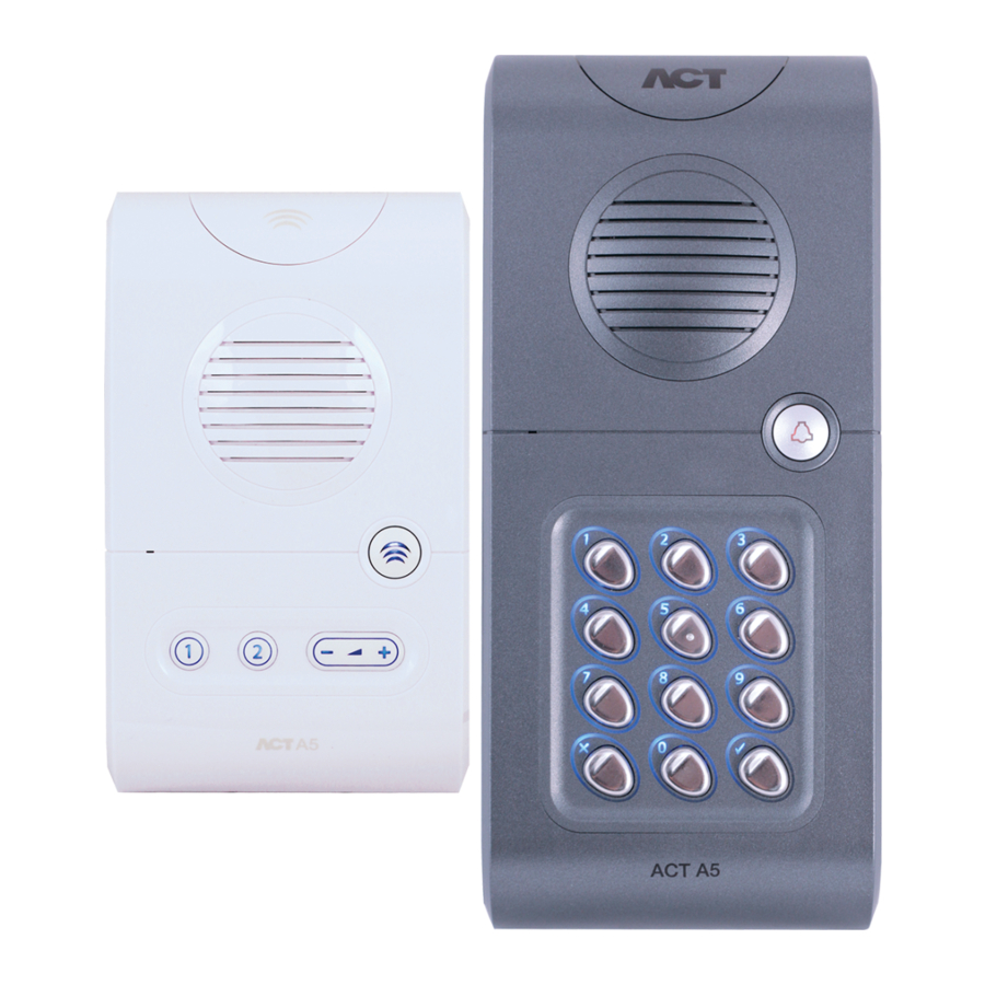
ACTentry A5 Operating and Installation Manual Rev 1.1 ACTentry A5 Entry Panel The Entry Panel is securely mounted on the wall at the entrance to the premises. It consists of a speaker grille (label 2), CALL button for visitors (label 3) and a keypad (label 4). The keypad is used for PIN code access or to configure the unit. -
Page 7: Power Supply
Cable Cable Requirements: For optimum speech clarity, it is strongly recommended that the ACTentry A5 system is installed using CAT5 cable or equivalent. For external use it is recommended to use external rated CAT 5 or equivalent. -
Page 8: Actentry A5 Entry Panel Installation
ACTentry A5 Operating and Installation Manual Rev 1.1 ACTentry A5 Entry Panel Installation The ACTentry Entry Panel is made from 2 separate parts: a front unit and a base unit. The front unit contains the speaker and keypad. The base unit contains the electronics, microphone and connector blocks. -
Page 9: Actentry A5 Intercom Installation
ACTentry A5 Operating and Installation Manual Rev 1.1 ACTentry A5 Intercom Installation The ACTentry Intercom is made from 2 separate parts: a front unit and a base unit. The front unit contains the speaker and keypad. The base unit contains the electronics, microphone and connector blocks. -
Page 10: Installation Steps
ACTentry A5 Operating and Installation Manual Rev 1.1 Installation steps 1.Fix the base units of the Entry Panel and Intercom to the wall and connect as shown below. 2. Attach the keypad and speaker cables to their connectors on the base unit. Handle these connections with care! Both connectors are polarised and can only go in ONE way. - Page 11 ACTentry A5 Operating and Installation Manual Rev 1.1 7.Test the audio quality. The volume on the Entry Panel and Intercom is set in the factory which should be suitable for most environments, if the volume is too low or high for the installed environment then further adjusted can be made manually.
-
Page 12: Actentry A5 Programming
ACTentry A5 Operating and Installation Manual Rev 1.1 ACTentry A5 Programming On the Entry Panel, press the button followed by the programming code (initially 9999). The CALL led will flash amber while in programming mode. If is pressed at any time or no key is pressed within 30 seconds, programming mode is exited. -
Page 13: Relay Timers
ACTentry A5 Operating and Installation Manual Rev 1.1 Relay Timers Relay timers are set in the factory to 5 seconds. Timers may be set to any duration between 2 seconds and 4 minutes. Step Keypad Entry Operation Enter Programming Mode... -
Page 14: Backlight Settings
During this time, the Call button will flash red and all user codes will be inactive. Restoring Factory Defaults The ACTentry A5 entry panel may be returned to its factory default settings at any time by entering the programming mode and pressing the tick ( ) key three times. -
Page 15: Troubleshooting
ACTentry A5 Operating and Installation Manual Rev 1.1 Troubleshooting Low Speech Volume at the Entry Panel 1. Volume adjustment required on the Entry Panel. 2. Entry Panel grill is blocked 3. Entry Panel or Intercom/Phone supply voltage is low (Minimum of 15V DC required) No speech when the Intercom/Phone is buzzed 1. -
Page 16: Actentry A5 And Intercom Configuration With Dc Psu
ACTentry A5 Operating and Installation Manual Rev 1.1 ACTentry A5 and Intercom Configuration with DC PSU ACTentry A5 Entry Panel with Intercom and Phone Configuration... -
Page 17: Actentry A5 And Switch Unit Configuration
ACTentry A5 Operating and Installation Manual Rev 1.1 ACTentry A5 and Switch Unit Configuration... -
Page 18: Actentry A5 And Intercom Configuration With Ac Psu
ACTentry A5 Operating and Installation Manual Rev 1.1 ACTentry A5 and Intercom Configuration with AC PSU ACTentry A5 Dimensioned Diagram Measurements in mm... -
Page 19: User List
ACTentry A5 Operating and Installation Manual Rev 1.1 User List User User Name Toggle Example: 7529 John Smith...
Need help?
Do you have a question about the ACTENTRY A5 and is the answer not in the manual?
Questions and answers