Table of Contents
Advertisement
TJERNLUND PRODUCTS, INC.
1601 Ninth Street • White Bear Lake, MN 55110-6794
PHONE (651) 426-2993 • (800) 255-4208 • FAX (651) 426-9547
Visit our web site • www.tjernlund.com
INSTALLATION INSTRUCTIONS
Recognize this symbol as an indication of important safety information!
!
OWNER INSTRUCTIONS, DO NOT DESTROY
CAUTION: The owner of the SS2 must keep the area around the vent terminal
!
free of snow, ice and debris.
NOTE: MAXIMUM FLUE GAS TEMPERATURES MUST NOT EXCEED 650 o F
(343
O
C) MINIMUM TEMPERATURE MUST BE 250
TEM INLET.
THESE INSTRUCTIONS ARE INTENDED AS AN AID TO QUALIFIED, LICENSED SERVICE PER-
SONNEL FOR PROPER INSTALLATION, ADJUSTMENT AND OPERATION OF THIS UNIT.
READ THESE INSTRUCTIONS THOROUGHLY BEFORE ATTEMPTING INSTALLATION OR
OPERATION. FAILURE TO FOLLOW THESE INSTRUCTIONS MAY RESULT IN IMPROPER
INSTALLATION, ADJUSTMENT, SERVICE OR MAINTENANCE POSSIBLY RESULTING IN FIRE,
ELECTRICAL SHOCK, CARBON MONOXIDE POISONING, EXPLOSION, PERSONAL INJURY
OR PROPERTY DAMAGE.
NOTE: Burner capacities exceeding 1 GPH may require the burner to be adjusted to more
efficient (12.5-13% CO
settings. See "Draft Adjustment Procedure" on page 12 of this manual or consult
factory at 1-800-255-4208 with questions prior to installation.
DO NOT DESTROY. PLEASE READ CAREFULLY AND
KEEP IN A SAFE PLACE FOR FUTURE REFERENCE.
Copyright © 1999, Tjernlund Products, Inc. All rights reserved.
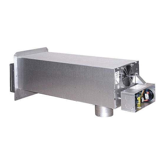
MODEL SS2
) than typical levels to maintain recommended over-fire draft
2
O
F (121
O
C) AT VENT SYS-
REV. B 11/99
P/N 8504063
Advertisement
Table of Contents
Troubleshooting

Related Manuals for TJERNLUND SS2 SIDESHOT (DISCONTINUED VERSION-PRE UC1 UNIVERSAL CONTROL) 8504063 REV B 1199


Summary of Contents for TJERNLUND SS2 SIDESHOT (DISCONTINUED VERSION-PRE UC1 UNIVERSAL CONTROL) 8504063 REV B 1199
-
Page 1: Installation Instructions
See “Draft Adjustment Procedure” on page 12 of this manual or consult factory at 1-800-255-4208 with questions prior to installation. DO NOT DESTROY. PLEASE READ CAREFULLY AND KEEP IN A SAFE PLACE FOR FUTURE REFERENCE. Copyright © 1999, Tjernlund Products, Inc. All rights reserved. P/N 8504063... -
Page 2: Table Of Contents
Customer Service Tjernlund Products, Inc. 1601 Ninth Street White Bear Lake, MN 55110-6794 Call us toll free at 800-255-4208, visit our web site @ www.tjernlund.com or E-mail us at fanmail@tjfans.com. TABLE OF CONTENTS Page (s) Description and Specifications ............................1, 2 Installation Restrictions ..............................2... -
Page 3: Installation Restrictions
SPECIFICATIONS Motor: 115/1/60, 3000 RPM, 1/25 HP, 1.6 FLA, Ball Bearing Permanently Lubricated. Fan Proving Switch: Non-adjustable set point of -.40” W.C. on pressure drop. Contacts rated for an inductive load of 6.2 FLA. High Limit: Manual reset N/C contacts, open at 170 o F + 8 o F (77 o C + 5 o C). Contacts rated at 10 FLA at 120 VAC. Post-Purge Timer: Adjustable from 1 to 10 minutes. -
Page 4: Cautions
CAUTIONS 1. Disconnect power supply from the SS2 and heating equipment when making wiring connections and servicing the SS2. Failure to do so may result in personal injury and/or equipment damage. 2. Failure to install, maintain and/or operate the SS2 in accordance with manufacturer's instructions may result in conditions which can produce bodily injury and property damage. -
Page 5: Vent Hood Termination Clearances U.s. Installations
VENT HOOD TERMINATION CLEARANCES FOR U.S. INSTALLATIONS The SS2 has been ETL Listed according to the requirements of the National Fire Protection Association #31, and #211 as follows below, (See Diagram A). • The exit terminals of mechanical draft systems shall not be less than 7 feet above grade when located adjacent to public walkways. •... -
Page 6: Canadian Installations
VENT HOOD TERMINATION CLEARANCES FOR CANADIAN INSTALLATIONS The SS2 has been CSA Listed according to the requirements of “Mechanical Flue-Gas Exhausters” CSA Std B255-M81 and the “Installation code for Oil burning Equipment” CSA Std B139-M91, (See Diagram A1). • A venting system shall not terminate underneath a veranda, porch, or deck, or above a paved sidewalk or a paved driveway that is located between two buildings, and that serves both buildings. - Page 7 SS2 VENT SYSTEM CLEARANCES FROM COMBUSTIBLES & OBSTRUCTIONS With an inlet flue gas temperature of 650 o F (343 o C) or below, the SS2 has been Listed for Zero Clearance from combustibles. NOTE: You must allow a minimum 2 foot distance of unobstructed clearance behind the SS2 Vent System for doing maintenance.
-
Page 8: Vent System Installation
NOTE: For easy one person installations, remove (9) screws from rear and bottom of vent cabinet. Slide venter assembly out of SS2 cabinet and set aside being careful not to damage housing. After SS2 cabinet is secured to the outside wall, and the vibration isolation mount is installed to the inside wall, replace venter assembly and (9) screws, (See Diagram D). -
Page 9: Installation Of Vent Pipe
4. a) If installing the bracket into a wood wall, drill 2 pilot holes at each point established in step 3 with a 1/8" drill bit approximately 1" deep and install the screws provided to secure the bracket to the wall. If installing the bracket into a masonry wall, drill 2 holes at each point established in step 3 with a 1/4"... -
Page 10: Electrical Wiring
ELECTRICAL WIRING OIL All wiring from the SS2 to the appliance must be appropriate Class 1 wiring as follows: installed in rigid metal conduit, intermediate metal conduit, rigid non-metallic conduit, electrical metallic tubing, Type MI Cable, Type MC Cable, or be otherwise suitably protected from physical damage. - Page 11 SS2 CONNECTED TO AN R8184G WITH THE APPLIANCE BURNER MOTOR LESS THAN 6.2 AMPS @ 120 VAC LADDER DIAGRAM CONNECTION DIAGRAM NOTES: The SS2 is normally interlocked with the primary control of the appliance. Wire all other furnace/boiler controls as normally done when conventional venting before continuing.
-
Page 12: Wiring To Oil Fired Appliance
SS2 CONNECTED TO 24 VAC THERMOSTAT CIRCUIT WITH BURNER MOTOR POST PURGE (P/N 950-2043) (USE IN CONJUNCTION WITH DIAGRAM ON BOTTOM OF PAGE 10) SS2 CONNECTED TO A RIELLO BURNER SS2 CONNECTED TO A CARLIN CONTROL... -
Page 13: Draft Adjustment Procedure
Do not allow heating system to run at less than a -.02” W.C. over fire draft or at a CO level that is less than a 1% reduction from the value measured at a trace of smoke and a -.02” W.C. over fire draft. If these parameters are unobtainable, contact Tjernlund at 1-800-255-4208 for Technical Assistance. -
Page 14: Combustion Air
Accessory air intakes are available that connect to the burner motor, using it to pull in the outdoor air. The Tjernlund IN-FORCER Combustion Air Intake tempers the raw outdoor air as it is delivered to the burner. -
Page 15: Troubleshooting Electrical Problems
Extreme caution must be exercised to prevent injury. If you are unable to determine the defective part with the use of this guide, call your Tjernlund distributor or Tjernlund Products direct at 1-800-255-4208 for further assistance. SYMPTOM 1: SS2 MOTOR RUNS CONTINUOUSLY Remove the external control wire attached to terminal "O"... - Page 16 SYMPTOM 3: APPLIANCE WILL NOT OPERATE, BUT SS2 DOES Step1. Set draft adjustment according to "Draft Verify draft adjustment has been made. Adjustment Procedure" on page 12. SS2 and appliance are not interlocked Step 2. correctly or malfunction of appliance controls. With the appliance calling for heat and SS2 Refer to electrical diagrams in this manual and operating, verify proper control voltage exists...
-
Page 17: Maintenance
Tjernlund Products, Inc. will issue credit or provide a free part to replace one that becomes defective during the two year warranty period. If the part is over 30 months old, proof of date of the installation in the form of the contractor sales/installation receipt is necessary to prove the unit has been in service for under two years. - Page 18 TJERNLUND LIMITED TWO YEAR WARRANTY Tjernlund Products, Inc. warrants to the original purchaser of this product that the product will be free from defects due to faulty material or work- manship for a period of (2) years from the date of original purchase or delivery to the original purchaser, whichever is earlier. Remedies under this warranty are limited to repairing or replacing, at our option, any product which shall, within the above stated warranty period, be returned to Tjernlund Products, Inc.
Need help?
Do you have a question about the SS2 SIDESHOT (DISCONTINUED VERSION-PRE UC1 UNIVERSAL CONTROL) 8504063 REV B 1199 and is the answer not in the manual?
Questions and answers