Table of Contents
Advertisement
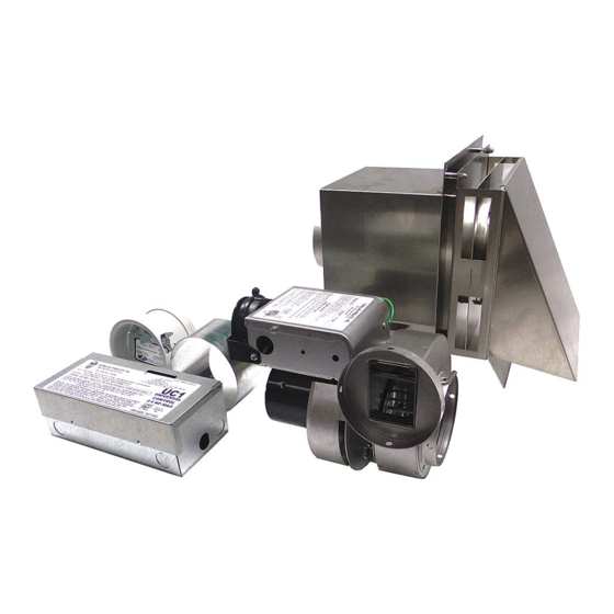
MODELS
DESCRIPTION
GPAK-J
FOR GAS APPLIANCES WITH A BTU/HR INPUT OF 120,000 OR LESS
GPAK-JT
FOR GAS APPLIANCES WITH A BTU/HR INPUT OF 120,000 OR LESS
WHICH REQUIRE A POWER VENTER POST PURGE
GPAK-1
FOR GAS APPLIANCES WITH A BTU/HR INPUT FROM 100,000 TO 250,000
GPAK-1T
FOR GAS APPLIANCES WITH A BTU/HR INPUT FROM 100,000 TO
250,000 WHICH REQUIRE A POWER VENTER POST PURGE
OWNER INSTRUCTIONS, DO NOT DESTROY
!
Recognize this symbol as an indication of important Safety Information!
NOTE: FLUE GAS TEMPERATURES MUST NOT EXCEED
o
600
F AT VENT SYSTEM INLET.
THESE INSTRUCTIONS ARE INTENDED AS AN AID TO QUALIFIED, LICENSED
SERVICE PERSONNEL FOR PROPER INSTALLATION, ADJUSTMENT AND
OPERATION OF THIS UNIT. READ THESE INSTRUCTIONS THOROUGHLY
BEFORE ATTEMPTING INSTALLATION OR OPERATION. FAILURE TO FOLLOW
THESE INSTRUCTIONS MAY RESULT IN IMPROPER INSTALLATION, ADJUST-
MENT, SERVICE OR MAINTENANCE POSSIBLY RESULTING IN FIRE, ELECTRI-
CAL SHOCK, CARBON MONOXIDE POISONING, EXPLOSION, OR PERSONAL
INJURY OR PROPERTY DAMAGE.
DO NOT DESTROY. PLEASE READ CAREFULLY AND KEEP
IN A SAFE PLACE ON JOB SITE FOR FUTURE REFERENCE.
Copyright © 1995, Tjernlund Products, Inc. All rights reserved.
TJERNLUND PRODUCTS, INC.
1601 Ninth Street • White Bear Lake, MN 55110-6794
PHONE (800) 255-4208 • (651) 426-2993 • FAX (651) 426-9547
Visit our web site • www.tjernlund.com
REV. 3 9/97
P/N 8504013
Advertisement
Table of Contents

Related Manuals for TJERNLUND GPAK-J,JT,1,1T (DISCONTINUED) 8504013 REV 3 0997


Summary of Contents for TJERNLUND GPAK-J,JT,1,1T (DISCONTINUED) 8504013 REV 3 0997
- Page 1 CAL SHOCK, CARBON MONOXIDE POISONING, EXPLOSION, OR PERSONAL INJURY OR PROPERTY DAMAGE. DO NOT DESTROY. PLEASE READ CAREFULLY AND KEEP IN A SAFE PLACE ON JOB SITE FOR FUTURE REFERENCE. Copyright © 1995, Tjernlund Products, Inc. All rights reserved. P/N 8504013...
-
Page 2: Table Of Contents
PERFORMANCE CURVES ........................... 16-17 VH1-4 VENT HOOD MOUNTING TEMPLATE ......................18 Tjernlund Products welcomes your comments and questions. Call us at 1-800-255-4208, Fax 612-426-9547 or write to: Customer Service, Tjernlund Products, Inc., 1601 Ninth Street, White Bear Lake, MN 55110-6794. -
Page 3: Specifications
EQUIVALENT PIPE LENGTH CALCULATION EXAMPLE SPECIFICATIONS ELECTRICAL SPECIFICATIONS POWER VENTER INSTALLATION VENT HOOD INSTALLATION RESTRICTIONS Do not install the Power Venter on incinerators, condensing type appliances or solid-fuel burning appliances. Only install the Power Venter on appliances equipped with a draft hood, draft diverter or barometric draft control. Do not install the Power Venter on an appliance with an automatic valve having a manual opener unless the manual opener has been rendered inoperative or the automatic valve has been replaced with a valve not equipped with a manual opener. -
Page 4: Installer Notes
The Power Venter must be installed by a qualified installer in accordance with these instructions and all local codes or in their absence in accordance with the latest edition of The National Fuel Gas Code (NFPA #54), the latest edition of the National Electrical Code (NFPA#70) and the Occupational Safety and Health Act (OSHA) when applicable. -
Page 5: Safety Inspection Of Existing Appliance Installation
*SAFETY INSPECTION OF A PREVIOUSLY USED GAS APPLIANCE (Perform prior to GPAK installation) The following procedure is intended as a guide to aid in determining that an appliance is properly installed and is in safe condition for continuing use. The following procedure is based on central furnace and boiler installations and it should be recognized that generalized procedures cannot anticipate all situations. - Page 6 VENT HOOD INSTALLATION 1. Attach the template on page 18 to the interior of the wall the vent hood will be penetrating. 2. Verify that wall penetration will not come in contact with concealed wiring or plumbing. Using a 1/2” drill bit, drill two pilot holes where noted on the template.
- Page 7 DRAFT CONTROL INSTALLATION When installing any GPAK-Series Side Wall Venting System on a fan assisted furnace a barometric draft control must be added. The draft control provides pressure relief to neutralize over-drafting and allows a means of draft adjustment for optimum furnace efficiency. By adjusting the draft control the installer can obtain the furnace manufacturer’s recommended draft setting.
-
Page 8: Electrical Wiring
2. To facilitate installation and reduce vibration we have included 2 mounting DIAGRAM F brackets, 2 rubber isolaters and 2 rubber grommets. One of the brackets may be used temporarily as a third hand while positioning it for permanent installation. 3. -
Page 11: Alternative Wiring With Thermostat
NOTE: When Power Venter is interlocked with thermostat wire all zones, circulators and limits as would normally be done if venting into a chimney. If you are unable to wire the GPAK as outlined in these instructions, call Tjernlund’s Customer Service Department toll free at 1-800-255-4208 for fast assistance. - Page 12 WIRING GPAK-JT/GPAK-1T WITH THERMOSTAT...
-
Page 13: Operation Circuit Check
The delay is caused by the Power Venter Fan Proving Switch. The delay will be no more than 4 seconds, if you are unable to detect a slight delay, contact Tjernlund Products, Inc. at 1-800-255-4208 for assistance. -
Page 14: Air Flow Adjustment
115 Volts. Extreme caution must be exercised to prevent injury. If you are unable to determine the defective part with the use of this guide, call your Tjernlund distributor or Tjernlund Products direct at... - Page 15 Ignition Module MV - MV/PV) or (Standing Pilot TH - Hot & TR - Common). Interlocked with thermostat at furnace Check for voltage across W & C at thermostat. 24 Volts not present Contact Tjernlund Products, Inc. for additional assistance.
-
Page 16: How To Obtain Service & Limited Warranty
Tjernlund Products, Inc. will issue credit to the original distributor or provide a free part to replace one that becomes defective during the one year warranty period. If the part is over 18 months old, proof of date of the installation in the form of the contractor sales/installa- tion receipt is necessary to prove the unit has been in service for under one year. -
Page 17: Performance Curves
TJERNLUND LIMITED ONE YEAR WARRANTY Tjernlund Products, Inc. warrants to the original purchaser of this product that the product will be free from defects due to faulty material or workmanship for a period of (1) year from the date of original purchase or delivery to the original purchaser, whichever is earlier. Remedies under this warranty are limited to repairing or replacing, at our option, any product which shall, within the above stated warranty period, be returned to Tjernlund Products, Inc. - Page 18 GPAK-1/GPAK-1T...
-
Page 19: Vh1-4 Vent Hood Mounting Template
VH1-4 VENT HOOD MOUNTING TEMPLATE 1. Attach the Vent Hood Mounting Template to the interior of the wall the vent hood will be penetrating. 2. Verify that wall penetration will not come in contact with concealed wiring or plumbing. Using a 1/2” drill bit, drill two pilot holes where noted on the template.
Need help?
Do you have a question about the GPAK-J,JT,1,1T (DISCONTINUED) 8504013 REV 3 0997 and is the answer not in the manual?
Questions and answers