Advertisement
Quick Links
TJERNLUND PRODUCTS, INC.
1601 Ninth Street • White Bear Lake, MN 55110-6794
PHONE (800) 255-4208 • (651) 426-2993 • FAX (651) 426-9547
Visit our web site • www.tjernlund.com
INSTALLATION INSTRUCTIONS
Recognize this symbol as an indication of important Safety Information!
!
OWNER INSTRUCTIONS, DO NOT DESTROY
THESE INSTRUCTIONS ARE INTENDED AS AN AID TO QUALIFIED, LICENSED
SERVICE PERSONNEL FOR PROPER INSTALLATION, ADJUSTMENT AND
OPERATION OF THIS PRODUCT. READ THESE INSTRUCTIONS THOROUGHLY
BEFORE ATTEMPTING INSTALLATION OR OPERATION. FAILURE TO FOLLOW
THESE INSTRUCTIONS MAY RESULT IN IMPROPER INSTALLATION, ADJUST-
MENT, SERVICE OR MAINTENANCE POSSIBLY RESULTING IN FIRE, ELECTRI-
CAL SHOCK, CARBON MONOXIDE POISONING, EXPLOSION, OR PERSONAL
INJURY OR PROPERTY DAMAGE.
DO NOT DESTROY. PLEASE READ CAREFULLY AND
KEEP IN A SAFE PLACE FOR FUTURE REFERENCE.
Copyright © 2004, Tjernlund Products, Inc. All rights reserved
MODEL UC1
REV. C 02/04
VERSION
X.04
P/N 8504107
Advertisement

Related Manuals for TJERNLUND UC1 UNIVERSAL CONTROL (VERSION X.04) 8504107 REV C 0204


Summary of Contents for TJERNLUND UC1 UNIVERSAL CONTROL (VERSION X.04) 8504107 REV C 0204
-
Page 1: Installation Instructions
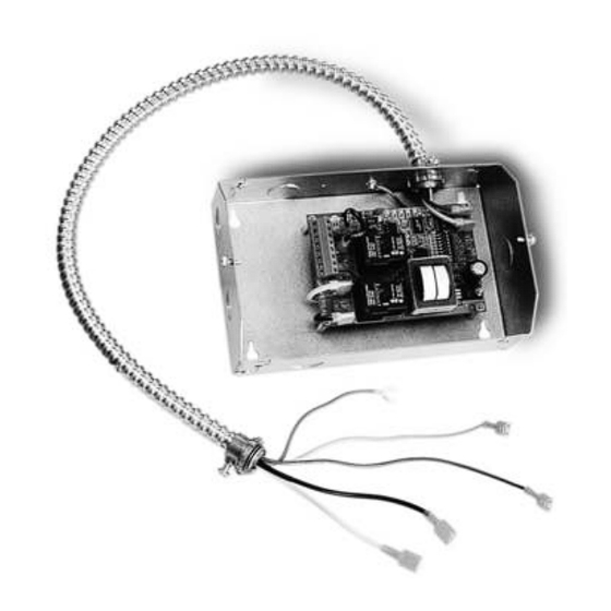
MENT, SERVICE OR MAINTENANCE POSSIBLY RESULTING IN FIRE, ELECTRI- CAL SHOCK, CARBON MONOXIDE POISONING, EXPLOSION, OR PERSONAL INJURY OR PROPERTY DAMAGE. DO NOT DESTROY. PLEASE READ CAREFULLY AND KEEP IN A SAFE PLACE FOR FUTURE REFERENCE. Copyright © 2004, Tjernlund Products, Inc. All rights reserved P/N 8504107... - Page 2 DESCRIPTION The UC1 is the new standard interlock control for Tjernlund's full line of Power Venters, Draft Inducers and Combustion Air In-Forcers. It can be interlocked with virtually any burner control circuit. Features include: adjustable pre & post purge, LED status / diagnostic indicators, 10 second prover switch delay to avoid burner start up and wind induced short cycling.
- Page 3 P1 - P2 SAFETY CIRCUIT C, GND, F AUXILIARY DEVICE TERMINALS COMMUNICATION TERMINALS 1 mA @ 5VDC. 2 mA @ 5VDC. For Tjernlund MAC1E or SEE WARNING # 1. MAC4E auxiliary devices. SEE WARNING # 1. DIP SWITCH SETTINGS Pre-Purge (1-2)
- Page 4 LED STATUS INDICATORS LED #4 & #5 (Red) Flashing Alternately = Venter in Pre-purge. (Pre-Purge options 0, 5, 20, 35 seconds) LED #4 & #5 (Red) Flashing in Unison = Venter in Post-Purge. (Post-Purge options 0, 30 seconds or 1, 2, 4, 8, 16 minutes) LED #4 Flashes Continuously* = Fan Prover opened for more than 10 seconds during burner cycle.
- Page 5 CIRCUIT PROTECTION PROVIDED BY INSTALLER 150 mA MAX @ 120 VAC, 50/60 Hz XL / XN CAN ONLY BE CONNECTED TO TJERNLUND-SPECIFIED AUXILIARY DEVICE ADD VENTER MOTOR UC1 CONTROL DURING OPERATION THE CONTROL USES 50 mA MAX @ 120 VAC...
- Page 6 The steps listed under each diagram are intended as a supplement to the diagram. Wiring colors or designations may vary by manufacturer. If you are unable to wire the UC1 as outlined in these instructions, call Tjernlund’s Customer Service Department toll free at 1-800-255-4208 for assistance.
- Page 7 VENTER GROUND, MOTOR AND PROVER SAFETY CIRCUIT CONNECTIONS VENTER PROVER CONNECTIONS Blue and Yellow leads from UC1 whip (P1 and P2) safety circuit must be connected to a Fan Prover switch. Leads are not polarity sensitive. If using a Draft Inducer and venting only millivolt appliances, the PS1505 Fan Prover is not needed. See WHKE instructions or consult factory.
- Page 8 UC1 UNIVERSAL CONTROL CONNECTED WITH A SINGLE ZONE 24 VAC THERMOSTAT IMPORTANT: RED JUMPER POSITION MUST BE THE SAME AS APPLIANCE INTERLOCK VOLTAGE. THERMOSTAT CALL JUMPER SUPPLY INTERNAL CONTROL LEGEND: 115 VAC OF FURNACE 50/60 Hz 115 VAC GROUND 24 VAC IMPORTANT: D/N 9183046-5 CRIMP GROUND WIRE TO GROUNDING...
- Page 9 UC1 UNIVERSAL CONTROL AND WHKE INTERLOCK KIT CONNECTED WITH A MILLIVOLT APPLIANCE IMPORTANT: RED JUMPER POSITION MUST BE THE SAME AS APPLIANCE INTERLOCK VOLTAGE. VALVE LEGEND: 115 VAC CALL 5 VDC JUMPER BOARD- WHKE GAS LINEAR LIMIT GENERATED PRESSURE SPILL SWITCH POWER.
- Page 10 UC1 UNIVERSAL CONTROL CONNECTED TO A HONEYWELL R7184 SERIES OR EQUIVALENT PRIMARY CONTROL WITH A LINE VOLTAGE THERMOSTAT OR AQUASTAT SUPPLY 115 VAC R7184 LEGEND: 60 Hz 115 VAC Low Voltage Limit D/N 9183046-6 Line Voltage Thermostat Limit Jumper or Aquastat Control IMPORTANT: RED JUMPER POSITION MUST BE THE SAME AS APPLIANCE INTERLOCK VOLTAGE.
- Page 11 UC1 UNIVERSAL CONTROL CONNECTED TO AN OIL-FIRED FURNACE WITH A HONEYWELL T87 OR EQUIVALENT NON-POWERED THERMOSTAT IMPORTANT: RED JUMPER POSITION MUST BE THE SAME AS APPLIANCE INTERLOCK VOLTAGE. HONEYWELL T87 OR EQUIVALENT NON-POWERED THERMOSTAT IMPORTANT: REMOVE JUMPER TO AVOID BACKFEEDS OR SHORT CIRCUITS.
- Page 12 UC1 UNIVERSAL CONTROL CONNECTED WITH A HONEYWELL R8184 SERIES OR EQUIVALENT PRIMARY CONTROL AND A BURNER MOTOR POST-PURGE CONNECT TO L1 OR B1 THERMOSTAT BLACK IMPORTANT: ORANGE RED JUMPER POSITION MUST BE THE SAME AS APPLIANCE INTERLOCK VOLTAGE. WHITE HONEYWELL R8184 CALL SERIES OR EQUIVALENT JUMPER...
- Page 13 Extreme caution must be exercised to prevent injury. If you are unable to determine the defective part with the use of this guide, call your Tjernlund distributor or Tjernlund Products direct at 1-800-255-4208 for further assistance.
- Page 14 LED FAULT INDICATORS Fault conditions are indicated by counting the number of times LED #4 (Red) flashes. LED #4 Flashes 2 Times Fan Prover was in electrically closed position prior to venter operation. LED #4 Flashes 3 Times* Fan Prover does not close within 60 seconds after call for heat. LED #4 Flashes 4 Times* Fan Prover did not re-close after 10 minutes of Venter operation.
- Page 15 TJERNLUND LIMITED ONE YEAR WARRANTY Tjernlund Products, Inc. warrants to the original purchaser of this product that the product will be free from defects due to faulty material or work- manship for a period of (1) year from the date of original purchase or delivery to the original purchaser, whichever is earlier. Remedies under this warranty are limited to repairing or replacing, at our option, any product which shall, within the above stated warranty period, be returned to Tjernlund Products, Inc.
Need help?
Do you have a question about the UC1 UNIVERSAL CONTROL (VERSION X.04) 8504107 REV C 0204 and is the answer not in the manual?
Questions and answers