TJERNLUND DJ-3, D-3, HD, I, IL, XL DRAFT INDUCER 8504003 REV A 0700 Installation Instructions Manual
Inducer
Hide thumbs
Also See for DJ-3, D-3, HD, I, IL, XL DRAFT INDUCER 8504003 REV A 0700:
- Specifications (7 pages) ,
- Manual (4 pages) ,
- Reference manual (4 pages)
Table of Contents
Advertisement
TJERNLUND PRODUCTS, INC.
1601 Ninth Street • White Bear Lake, MN 55110-6794
PHONE (800) 255-4208 • (651) 426-2993 • FAX (651) 426-9547
Visit our web site • www.tjernlund.com
AUTO-DRAFT
INSTALLATION INSTRUCTIONS
OWNER INSTRUCTIONS, DO NOT DESTROY
!
Recognize this symbol as an indication of important Safety Information!
NOTE: FLUE GAS TEMPERATURES MUST NOT EXCEED
o
575
F AT DRAFT INDUCER INLET. DRAFT INDUCERS MUST NOT
BE USED FOR SIDEWALL VENTING APPLICATIONS.
THESE INSTRUCTIONS ARE INTENDED AS AN AID TO QUALIFIED, LICENSED
SERVICE PERSONNEL FOR PROPER INSTALLATION, ADJUSTMENT AND
OPERATION OF THIS UNIT. READ THESE INSTRUCTIONS THOROUGHLY
BEFORE ATTEMPTING INSTALLATION OR OPERATION. FAILURE TO FOLLOW
THESE INSTRUCTIONS MAY RESULT IN IMPROPER INSTALLATION, ADJUST-
MENT, SERVICE OR MAINTENANCE POSSIBLY RESULTING IN FIRE, ELECTRI-
CAL SHOCK, CARBON MONOXIDE POISONING, EXPLOSION, PERSONAL
INJURY OR PROPERTY DAMAGE.
DO NOT DESTROY. PLEASE READ CAREFULLY AND
KEEP IN A SAFE PLACE FOR FUTURE REFERENCE.
Copyright © 2000, Tjernlund Products, Inc. All rights reserved.
MODELS
DJ-3
D-3
I
INDUCER
®
IL
XL
HD
REV. A 7/00
P/N 8504003
Advertisement
Table of Contents

Related Manuals for TJERNLUND DJ-3, D-3, HD, I, IL, XL DRAFT INDUCER 8504003 REV A 0700


Summary of Contents for TJERNLUND DJ-3, D-3, HD, I, IL, XL DRAFT INDUCER 8504003 REV A 0700
-
Page 1: Installation Instructions
MENT, SERVICE OR MAINTENANCE POSSIBLY RESULTING IN FIRE, ELECTRI- CAL SHOCK, CARBON MONOXIDE POISONING, EXPLOSION, PERSONAL INJURY OR PROPERTY DAMAGE. DO NOT DESTROY. PLEASE READ CAREFULLY AND KEEP IN A SAFE PLACE FOR FUTURE REFERENCE. Copyright © 2000, Tjernlund Products, Inc. All rights reserved. P/N 8504003... -
Page 2: Table Of Contents
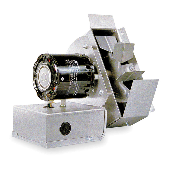
The venturi action of Tjernlund Auto-Draft Inducers starts air moving smoothly. These units are quick and easy to install and completely automatic in operation. Tjernlund’s unique design and durable con- struction makes them trouble-free and reduces maintenance to a minimum. The Vari-Draft Control permits adjustments to the individual job requirement. -
Page 3: Installation Restrictions
INSTALLATION RESTRICTIONS Failure to install, maintain and/or operate the Draft Inducer in accordance with manufacturer's instructions may result in conditions which can produce bodily injury and property damage. The Draft Inducer must be installed by a qualified installer in accordance with these instructions and all local codes or in their absence in accordance with the latest editions of The National Fuel Gas Code (NFPA #54), Installation of Fuel Burning Equipment (NFPA 31), Chimneys, Fireplaces, Vents, and Solid Fuel Burning Appliances (NFPA 211), The National Electrical Code (NFPA#70) and the Occupational Safety and Health Act (OSHA) when applicable. -
Page 4: Ps1505 Fan Prover Safety Interlock Installation
MODEL PS1505 FAN PROVING SWITCH SAFETY INTERLOCK The Model PS1505 Fan Proving Switch works on all Tjernlund Draft Inducers to assure adequate draft is present before burner is allowed to fire. The PS1505 complies with burner safety interlock provisions of National Mechanical Codes. - Page 5 4. Do not use “bullhead” tees when connecting two smoke pipes together. When tees are necessary, connect at 45 degree angles or less. If change in smokepipe size is required, use a tapered increaser or reducer. SIMPLE INSTALLATION 3. INSTALL BANDS 1.
-
Page 6: Electrical Wiring
TYPICAL INSTALLATION ELECTRICAL WIRING Wiring diagrams are included in these instructions for various draft inducer applications. While it would be impractical to show every conceivable variation, the ones included will demonstrate sufficient basic techniques for the design and installation of the unusual con- trol system. - Page 7 GAS WIRING TO ANY APPLIANCE EQUIPPED WITH 24V CONTROLS POST-PURGE RELAY/TIMER ON DRAFT INDUCER (DRAFT INDUCER MOTOR LESS THAN 4.4 AMPS) MODELS I, IL, XL MUST USE 950-0483 ISOLATION RELAY COMPONENTS NEEDED: (1) DRAFT INDUCER (1) PS1505 FAN PROVER (1) 950-1067 RELAY/TIMER MAXIMUM AMP LOAD IF DRAFT INDUCER MOTOR IS OVER 4.4 IS 4.4 AMPS...
- Page 8 DRAFT INDUCER CONNECTED WITH UP TO 4 24V GAS APPLIANCES WITH THE MAC-4 CONTROL (DRAFT INDUCER MOTOR LOAD GREATER THAN 1 H.P.) COMPONENTS NEEDED: (1) MAC-4 APPLIANCE CONTROL (1) DRAFT INDUCER (1) PS1505 FAN PROVER (1) ISOLATION RELAY/CONTACTOR NOTE: The MAC-4 is used for wiring up to 4 heating appliances with Draft Inducers, Power Venters or IN-FORCERs.
-
Page 9: Typical Oil Diagrams
DRAFT INDUCER CONNECTED WITH UP TO 4 115V GAS APPLIANCES WITH THE MAC-4 CONTROL (IF MOTOR LOAD IS GREATER THAN 1 H.P. AN ISOLATION RELAY WILL HAVE TO BE ADDED, SEE TOP OF PAGE 7) COMPONENTS NEEDED: (1) MAC-4 APPLIANCE CONTROL (1) DRAFT INDUCER (1) PS1505 FAN PROVER NOTE: The MAC-4 is used for... -
Page 10: Operation Circuit Check
PS1505 Fan Proving Switch proves draft. The delay is caused by the PS1505 Fan Proving Switch. If you are unable to detect a slight delay, contact Tjernlund Products, Inc. at 1-800-255-4208 for assistance. -
Page 11: P/N 950-1067 Post Purge Relay/Timer Adjustment
Many installers assume adequate combustion air is present, especially in older structures. In some cases this is a false assumption, because many structures have been made "tight" due to weatherization. Size the combustion air opening(s) into the appliance room as outlined NFPA 54/NFPA 211. Tjernlund’s IN-FORCER combustion air intake systems provide a convenient, interlocked way to supply combustion air to the utility room. -
Page 12: How To Obtain Service & Limited Warranty
TJERNLUND LIMITED ONE YEAR WARRANTY Tjernlund Products, Inc. warrants to the original purchaser of this product that the product will be free from defects due to faulty material or workmanship for a peri- od of (1) year from the date of original purchase or delivery to the original purchaser, whichever is earlier. Remedies under this warranty are limited to repairing or replacing, at our option, any product which shall, within the above stated warranty period, be returned to Tjernlund Products, Inc.
Need help?
Do you have a question about the DJ-3, D-3, HD, I, IL, XL DRAFT INDUCER 8504003 REV A 0700 and is the answer not in the manual?
Questions and answers