TJERNLUND 950-8804 UC1 UNIVERSAL CONTROL BOARD KIT (VERSION X.04) 8505017 REV A 0503 Manual
Version x.04
Hide thumbs
Also See for 950-8804 UC1 UNIVERSAL CONTROL BOARD KIT (VERSION X.04) 8505017 REV A 0503:
- Manual (17 pages)
Advertisement
Quick Links
Download this manual
See also:
Manual
950-8804 UNIVERSAL CONTROL LED STATUS AND FAULTS ADDENDUM (VERSION X.04)
IMPORTANT: The fault code indicators and LED sequencing have been changed with this software version of UC1 board. The
Pre-Purge settings, LED Status & Fault Indicators and Troubleshooting sections of your old instruction manual may not apply.
For Sideshot Series models SS1, SS1C & SS2 or HS-Series models HSJ,1,2,3,4,5 you can download updated instruction manuals
from our web site for your models which include the X.04 version updates. NOTE: Adhere appropriate included label over
existing label in UC1 or SideShot electrical box. Also adhere "Checking Memory for Last Fault Code" sticker on inside
of UC1 or SideShot SS1 Series electrical box. On SS2 Series adhere to underside of electrical box.
IMPORTANT: Note Dip Switch settings on existing UC1 circuit board so that
those same settings can be positioned on this replacement circuit board.
LED INDICATOR LIGHTS
LED 1 (Amber) Appliance call for heat.
LED 2 (Green) Safety circuit through P1 & P2 (Venter Fan Prover) is verified "Open" upon start-up. Indicates Venter
prover is closed during run cycle. Burner circuit is energized with contact closure from terminal 3 to 4.
LED 3 (Green) Power switched to Venter motor from L to MTR & M.
LED 4 (Red)
Status / Fault indicator.
LED 5 (Red)
115 VAC power supplied to board. Also used as a status indicator.
LED STATUS INDICATORS
LED 5 (Red) Steady On
LED 4 & 5 (Red) Flashing Alternately
LED 4 & 5 (Red) Flashing in Unison
LED 4 Flashes Continuously*
LED FAULT INDICATORS
Fault conditions are indicated by counting the number of times LED 4 flashes.
LED 4 Flashes 2 Times
LED 4 Flashes 3 Times*
LED 4 Flashes 4 Times*
LED 4 Flashes 5 Times*
* Investigate cause of Fan Prover short cycling such as; Firing burner at capacities or temperatures exceeding Venter limits,
excessive vent pipe runs, elbows directly on venter discharge, high winds, plugged / kinked Fan Prover sensing tube or a
faulty Fan Prover switch. In-Forcer model's intake screen and prefilter, if applicable, should be cleaned if necessary.
IMPORTANT: Fault codes will automatically be displayed after the given fault condition occurs. If the call for heat
interlock signal or 115 VAC power is removed, the UC1 circuit board will reset and the fault will not be automatically
displayed. The fault code will be stored in memory. Any new fault will replace any previous fault.
CHECKING MEMORY FOR LAST FAULT CODE
IMPORTANT: Prior to accessing the fault code memory, note the settings of the dip switches so that they can be returned to
their original Pre / Post-Purge positions. When power is supplied to the UC1 use caution when moving dip switches.
The last fault code can be retrieved at any time by setting all dip switches 1-8 to the up, or "on" position. The last fault code, or
lack there of, will be indicated by counting the number of times LED 4 flashes. By moving any of the dip switches back to their
original position, the fault code will be cleared. NOTE: The UC1 board must have its 115 VAC power supply present when any
of the (1-8) dip switches are moved back to their original position for the fault code to clear.
P/N: 8505017
TJERNLUND PRODUCTS, INC.
1601 Ninth Street • White Bear Lake, MN 55110-6794
PHONE (800) 255-4208 • (651) 426-2993 • FAX (651) 426-9547
Visit our web site • www.tjernlund.com
115 VAC power to UC1 circuit board
Pre-purge operation (Pre-Purge options 0, 5, 20, 35 seconds)
Post-Purge operation (Post-Purge options 0, 30 seconds or 1, 2, 4, 8, 16 minutes)
Fan Prover opened for more than 10 seconds during burner cycle.
(Venter will run for 10 minutes, attempting to make Fan Prover)
Fan Prover was in electrically closed position prior to venter operation.
Fan Prover does not close within 60 seconds after call for heat.
Fan Prover did not re-close after 10 minutes of Venter operation.
Fan Prover opened for more than 10 seconds during burner cycle but closed within 10 minutes.
©2003 TJERNLUND PRODUCTS, INC. ALL RIGHTS RESERVED
REV. A 05/03
Advertisement

Related Manuals for TJERNLUND 950-8804 UC1 UNIVERSAL CONTROL BOARD KIT (VERSION X.04) 8505017 REV A 0503


Summary of Contents for TJERNLUND 950-8804 UC1 UNIVERSAL CONTROL BOARD KIT (VERSION X.04) 8505017 REV A 0503
- Page 1 NOTE: The UC1 board must have its 115 VAC power supply present when any of the (1-8) dip switches are moved back to their original position for the fault code to clear. P/N: 8505017 ©2003 TJERNLUND PRODUCTS, INC. ALL RIGHTS RESERVED REV. A 05/03...
-
Page 2: Installation Instructions
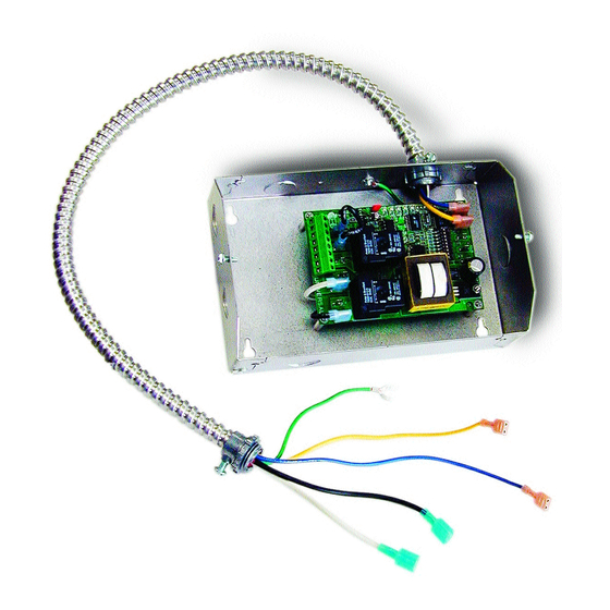
MENT, SERVICE OR MAINTENANCE POSSIBLY RESULTING IN FIRE, ELECTRI- CAL SHOCK, CARBON MONOXIDE POISONING, EXPLOSION, OR PERSONAL INJURY OR PROPERTY DAMAGE. DO NOT DESTROY. PLEASE READ CAREFULLY AND KEEP IN A SAFE PLACE FOR FUTURE REFERENCE. Copyright © 2003, Tjernlund Products, Inc. All rights reserved P/N 8504107... - Page 3 DESCRIPTION The UC1 is the new standard interlock control for Tjernlund's full line of Power Venters, Draft Inducers and Combustion Air In-Forcers. It can be interlocked with virtually any burner control circuit. Features include: adjustable pre & post purge, LED status / diagnostic indicators, 10 second prover switch delay to avoid burner start up and wind induced short cycling.
- Page 4 P1 - P2 SAFETY CIRCUIT C, GND, F AUXILIARY DEVICE TERMINALS COMMUNICATION TERMINALS 1 mA @ 5VDC. 2 mA @ 5VDC. For Tjernlund MAC1E or SEE WARNING # 1. MAC4E auxiliary devices. SEE WARNING # 1. DIP SWITCH SETTINGS Pre-Purge (1-2)
- Page 5 LED STATUS INDICATORS LED #4 & #5 (Red) Flashing Alternately = Venter in Pre-purge. (Pre-Purge options 0, 5, 20, 35 seconds) LED #4 & #5 (Red) Flashing in Unison = Venter in Post-Purge. (Post-Purge options 0, 30 seconds or 1, 2, 4, 8, 16 minutes) LED #4 Flashes Continuously = Fan Prover opened for more than 10 seconds during burner cycle.
- Page 6 CIRCUIT PROTECTION PROVIDED BY INSTALLER 150 mA MAX @ 120 VAC, 50/60 Hz XL / XN CAN ONLY BE CONNECTED TO TJERNLUND-SPECIFIED AUXILIARY DEVICE ADD VENTER MOTOR UC1 CONTROL DURING OPERATION THE CONTROL USES 50 mA MAX @ 120 VAC...
- Page 7 The steps listed under each diagram are intended as a supplement to the diagram. Wiring colors or designations may vary by manufacturer. If you are unable to wire the UC1 as outlined in these instructions, call Tjernlund’s Customer Service Department toll free at 1-800-255-4208 for assistance.
- Page 8 VENTER GROUND, MOTOR AND PROVER SAFETY CIRCUIT CONNECTIONS VENTER PROVER CONNECTIONS Blue and Yellow leads from UC1 whip (P1 and P2) safety circuit must be connected to a Fan Prover switch. Leads are not polarity sensitive. If using a Draft Inducer and venting only millivolt appliances, the PS1505 Fan Prover is not needed. See WHKE instructions or consult factory.
- Page 9 UC1 UNIVERSAL CONTROL CONNECTED WITH A SINGLE ZONE 24 VAC THERMOSTAT IMPORTANT: RED JUMPER POSITION MUST BE THE SAME AS APPLIANCE INTERLOCK VOLTAGE. THERMOSTAT CALL JUMPER SUPPLY INTERNAL CONTROL LEGEND: 115 VAC OF FURNACE 50/60 Hz 115 VAC GROUND 24 VAC IMPORTANT: D/N 9183046-5 CRIMP GROUND WIRE TO GROUNDING...
- Page 10 UC1 UNIVERSAL CONTROL AND WHKE INTERLOCK KIT CONNECTED WITH A MILLIVOLT APPLIANCE IMPORTANT: RED JUMPER POSITION MUST BE THE SAME AS APPLIANCE INTERLOCK VOLTAGE. VALVE LEGEND: 115 VAC CALL 5 VDC JUMPER BOARD- WHKE GAS LINEAR LIMIT GENERATED PRESSURE SPILL SWITCH POWER.
- Page 11 UC1 UNIVERSAL CONTROL CONNECTED TO A HONEYWELL R7184 SERIES OR EQUIVALENT PRIMARY CONTROL WITH A LINE VOLTAGE THERMOSTAT OR AQUASTAT SUPPLY 115 VAC R7184 LEGEND: 60 Hz 115 VAC Low Voltage Limit D/N 9183046-6 Line Voltage Thermostat Limit Jumper or Aquastat Control IMPORTANT: RED JUMPER POSITION MUST BE THE SAME AS APPLIANCE INTERLOCK VOLTAGE.
- Page 12 UC1 UNIVERSAL CONTROL CONNECTED TO AN OIL-FIRED FURNACE WITH A HONEYWELL T87 OR EQUIVALENT NON-POWERED THERMOSTAT IMPORTANT: RED JUMPER POSITION MUST BE THE SAME AS APPLIANCE INTERLOCK VOLTAGE. HONEYWELL T87 OR EQUIVALENT NON-POWERED THERMOSTAT IMPORTANT: REMOVE JUMPER TO AVOID BACKFEEDS OR SHORT CIRCUITS.
- Page 13 UC1 UNIVERSAL CONTROL CONNECTED WITH A HONEYWELL R8184 SERIES OR EQUIVALENT PRIMARY CONTROL AND A BURNER MOTOR POST-PURGE THERMOSTAT BLACK IMPORTANT: ORANGE RED JUMPER POSITION MUST BE THE SAME AS APPLIANCE INTERLOCK VOLTAGE. WHITE HONEYWELL R8184 CALL SERIES OR EQUIVALENT JUMPER OIL VALVE LEGEND:...
- Page 14 Extreme caution must be exercised to prevent injury. If you are unable to determine the defective part with the use of this guide, call your Tjernlund distributor or Tjernlund Products direct at 1-800-255-4208 for further assistance.
- Page 15 LED FAULT INDICATORS Fault conditions are indicated by counting the number of times LED #4 (Red) flashes. LED #4 Flashes 2 Times Fan Prover was in electrically closed position prior to venter operation. LED #4 Flashes 3 Times Fan Prover does not close within 60 seconds after call for heat. LED #4 Flashes 4 Times Fan Prover did not re-close after 10 minutes of Venter operation.
- Page 16 TJERNLUND LIMITED ONE YEAR WARRANTY Tjernlund Products, Inc. warrants to the original purchaser of this product that the product will be free from defects due to faulty material or work- manship for a period of (1) year from the date of original purchase or delivery to the original purchaser, whichever is earlier. Remedies under this warranty are limited to repairing or replacing, at our option, any product which shall, within the above stated warranty period, be returned to Tjernlund Products, Inc.
Need help?
Do you have a question about the 950-8804 UC1 UNIVERSAL CONTROL BOARD KIT (VERSION X.04) 8505017 REV A 0503 and is the answer not in the manual?
Questions and answers