Advertisement
- 1 TECHNICAL SPECIFICATIONS
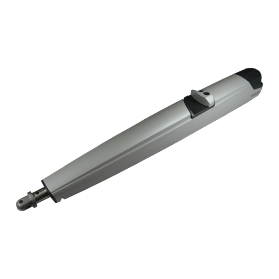
- 2 MAIN PARTS
- 3 STANDARD INSTALLATION
- 4 GATE ARRANGEMENT
- 5 INSTALLATION TYPE
- 6 INWARD INSTALLATION
- 7 OUTWARD INSTALLATION
- 8 INSTALLATION ON MASONRY PILLARS, MAKING A RECESS
- 9 CONNECTIONS
- 10 REAR FIXING BRACKET MOUNTING
- 11 FRONT FIXING BRACKET MOUNTING
- 12 MAGNETIC LIMIT SWITCHES
- 13 INTERNAL METAL RELEASE SYSTEM
- 14 PERIODIC MAINTENANCE
- 15 RISK EXAMINATION
- 16 GENERAL NOTICE FOR THE INSTALLER AND THE USER
- 17 Documents / Resources
TECHNICAL SPECIFICATIONS
KITE is an irreversible electro mechanical swing gate operator strong and safe, easy to install, for leaf length up to 5 m. KITE operator is equipped with release system through key, which allows the manual release of the leaf in case of emergency or black out

- Aluminium casing
- Front fixing bracket
- Back fixing bracket
- Release system
- Terminal board
- Capacitor
- Motor
- Metallic bever gear
- Bearings
- Endless-screw
- Lead screw barrel nut
USING GRAPHICS

| TECHNICAL DATA | KITE 500 H 24V | KITE 500 H BR 36V |
| Power supply | 24Vcc | 36Vcc |
| Max. Power | 60 W | 260 W |
| Max. Absorbed current | 2,5 A | 1 A |
| Stroke | 400 mm* | |
| Speed | ADJUSTABLE (MAX. 16") | ADJUSTABLE (MAX. 15") |
| Cycle/hour (operating at 20°C) | 50 | |
| Operating temperature | -20°C  +55°C  | |
| Anti-crushing Clutch | ELECTRONIC | |
| Max. thrust | 1800 N | 3000 N |
| Operator weight | 7,8 Kg | |
| Protection Class | Ip 44 | |
| Max. Leaf length | 5 m | |
| Max. Leaf weight | 500 Kg | |
Note: The frequency of use is valid only for the first hour at 20°C room temperature
* 370 mm with magnetic limit switch
DIMENSIONS (mm)

MAIN PARTS

STANDARD INSTALLATION

- Operator
- Mechanical stop
- Electronic control unit
- Flashing lamp
- Right Photocell (Dx)
- Differential switch 16A - 0,03A
- Left Photocell (Sx)
- Start/Stop push button with key
- Antenna
- Support for photocells
- Warning notice
* For KITE 24V operator use 2x2,5 cables type to connect the motors to the control unit
GATE ARRANGEMENT
Some checks on the gate are required to verify the KITE operator fitting;
Make sure that:
- the fix and the moving parts of the gate are strong and non-deformable;
- the length of each leaf does not exceed 5 m
- the weight of each leaf does not exceed 500 Kg
- the hinges and the general structure must be in good conditions and able to support the operator thrust; the gate must move smoothly throughout its whole travel;
Where possible, it is advisable to install mechanical stops on the ground for a good functioning of the operator

INSTALLATION TYPE
 INSTALL THE OPERATOR ALWAYS INSIDE THE PROPERTY

INWARD INSTALLATION

* The «f» dimension has been calculated for a 40 mm thick gate
| a (mm) | b (mm) | c (mm) | d max (mm) | e (mm) | f * (mm) | Stroke for 90° | Opening for 90° | Max Stroke for opening angle | Opening angle |
| 240 | 120 | 63 | 177 | 1210 | 140 | 360 | 90 | 381 | 100 |
| 250 | 120 | 63 | 187 | 1210 | 140 | 370 | 90 | 390 | 100 |
| 260 | 120 | 63 | 197 | 1210 | 140 | 380 | 90 | 394 | 95 |
| 210 | 100 | 63 | 147 | 1233 | 140 | 310 | 90 | 319 | 95 |
| 220 | 100 | 63 | 157 | 1233 | 140 | 320 | 90 | 329 | 95 |
| 230 | 100 | 63 | 167 | 1233 | 140 | 330 | 90 | 339 | 95 |
| 240 | 140 | 63 | 177 | 1193 | 140 | 380 | 90 | 394 | 95 |
| 230 | 140 | 63 | 167 | 1193 | 140 | 370 | 90 | 392 | 100 |
| 220 | 140 | 63 | 157 | 1193 | 140 | 360 | 90 | 389 | 105 |
| 220 | 160 | 63 | 157 | 1174 | 140 | 380 | 90 | 395 | 95 |
| 210 | 160 | 63 | 147 | 1174 | 140 | 370 | 90 | 395 | 100 |
| 200 | 160 | 63 | 137 | 1174 | 140 | 360 | 90 | 395 | 105 |
| 160 | 160 | 63 | 97 | 1175 | 140 | 320 | 90 | 371 | 115 |
| 160 | 180 | 63 | 97 | 1155 | 140 | 340 | 90 | 392 | 110 |
| 150 | 200 | 63 | 87 | 1137 | 140 | 350 | 90 | 400 | 105 |
| 140 | 210 | 63 | 77 | 1125 | 140 | 350 | 90 | 395 | 105 |
Total stroke 400 mm - max suggested stroke 380 mm
OUTWARD INSTALLATION

* The «f» dimension has been calculated for a 40 mm thick gate
| a (mm) | b (mm) | c (mm) | d max (mm) | e (mm) | f * (mm) | Stroke for 90° | Opening for 90° | Max Stroke for opening angle | Opening angle |
| 150 | 100 | 63 | 87 | 1045 | 140 | 250 | 90 | 259 | 95 |
| 150 | 120 | 63 | 87 | 1065 | 140 | 270 | 90 | 297 | 105 |
| 150 | 140 | 63 | 87 | 1085 | 140 | 290 | 90 | 330 | 110 |
| 160 | 120 | 63 | 97 | 1065 | 140 | 280 | 90 | 307 | 105 |
| 160 | 140 | 63 | 97 | 1085 | 140 | 300 | 90 | 331 | 105 |
| 160 | 160 | 63 | 97 | 1105 | 140 | 320 | 90 | 365 | 110 |
| 160 | 180 | 63 | 97 | 1125 | 140 | 340 | 90 | 392 | 110 |
| 180 | 140 | 63 | 117 | 1085 | 140 | 320 | 90 | 351 | 105 |
| 200 | 160 | 63 | 137 | 1104 | 140 | 360 | 90 | 394 | 105 |
Total stroke 400 mm - max suggested stroke 380 mm
INSTALLATION ON MASONRY PILLARS, MAKING A RECESS


During installation, make sure that the connection cables do not interfere with the recess
NOTES
- dimensions in mm
- In case you need to make a recess, observe the shown dimensions
CONNECTIONS
make connections only after installation is complete and when the power supply is OFF

PRELIMINARY NOTES
- For the correct operation it is very important to position both the operator and its front and rear fixing brackets, in a perfectly horizontal way, by using a level, as shown in Fig. 14
![]()
- Before mounting operator on the rear and the front brackets, lubricate with water repellent grease
- The operator must be mounted with the release facing upwards (Fig. 14)

REAR FIXING BRACKET MOUNTING
REAR FIXING BRACKET TO BE SCREWED
If the rear fixing bracket has to be screwed using the holes marked as «A», so the fixing bracket must be cut at a distance of 65 mm from its end (Fig. 15). It is not necessary to cut the bracket if using other holes

The support must be positioned so that the operator is in a perfect horizontal position (see Fig.14)
To avoid the oscillation of the operator during the operating phase, it is recommended to adjust the nut (1) (Fig. 16) taking care to not block the rotation of the operator on the fixing bracket


once the rear bracket has been fixed, immediately fix the front bracket, always keeping the operator in a horizontal position. Do not leave the front of the operator detached because it would fall down causing damage

PRELIMINARY NOTES
- According to the gate type (wood, iron, aluminium) the front bracket can be welded or screwed
- Before mounting the rear and the front fixing brackets, lubricate with water repellent grease
- The operator must be mounted with the release facing upwards (Fig. 14)
FRONT FIXING BRACKET MOUNTING
SCREWED FRONT FIXING BRACKET
Once the operator has been mounted on the rear fixing bracket, close the leaf and proceed as follows:
- Release the operator keeping it always in a horizontal position
- Screw the front fixing bracket onto the gate in correspondence of the holes made respecting the dimensions as per Fig. 18 and Fig. 19

- Insert the bracket into the housing pin on the operator (Fig. 20) and tighten the «A» screw to max 8.5 Nm
![]()


Lubricate the pin with grease before installing the front fixing bracket on the operator
WELDED FRONT FIXING BRACKET
Once the operator has been mounted on the rear fixing bracket, close the leaf and proceed as follows:
- Release the operator keeping it always in a horizontal position
- Weld the front fixing bracket on the gate operating on the points indicated by the arrows

- Insert the bracket into the housing pin on the operator (Fig. 20) and tighten the «A» screw to max 8.5 Nm

Lubricate the pin with grease before installing the front fixing bracket on the operator
MAGNETIC LIMIT SWITCHES

 TO THE ATTENTION OF THE TECHNICIAN AND THE END-USER
INTERNAL METAL RELEASE SYSTEM
TO RELEASE THE OPERATOR:
- Turn counter-clockwise the lock protection cover
![]()
- Insert the key and turn of about 90° clockwise
![]()
- Turn the handle counter-clockwise to release the operator
![]()


TO LOCK THE OPERATOR:
- Turn the handle clockwise to revert it to the initial position
- Turn the key about 90° counterclockwise
![]()
- After having relocked the operator, close the lock protection cover to prevent damages due to atmospheric agents

NOTE: for a proper operation of the manual release it is recommended to observe the current regulations regarding the thrust force
PERIODIC MAINTENANCE
ALL OPERATIONS MUST BE MADE EXCLUSIVELY BY AN AUTHORIZED INSTALLER AND WHEN POWER SUPPLY IS OFF
| 1 | Check the robustness and the stability of the gate, especially of the points of support and/or the gate points of rotation (pivots) | YEARLY |
| 2 | Check the release system function | YEARLY |
| 3 | Check and grease the fixing pivots and the endless screw | YEARLY |
| 4 | Check the integrity of the connection cables | YEARLY |
| 5 | Verify the function and the conditions of the mechanical stops in opening and closing | YEARLY |
| 6 | Verify the good condition of all mechanism subject to stress (as front and rear fixing brackets) | YEARLY |
| 7 | Check the function of all accessories, in particular of all safety devices | YEARLY |
AFTER THE PERIODICAL MAINTENANCE OPERATIONS IT IS NECESSARY TO REPEAT THE TEST OF THE AUTOMATION AND ITS COMMISSIONING
RISK EXAMINATION
The points pointed by arrows in Fig. 26 are potentially dangerous. The installer must take a thorough risk examination to prevent crushing, conveying, cutting, grappling, trapping so as to guarantee a safe installation for people, things and animals (Re. Laws in force in the Country where installation has been made). As for misunderstandings that may arise refer to your area distributor or call our help desk. These instructions are part of the device and must be kept in a well known place. The installer shall follow the provided instructions thoroughly. SEA products must only be used to automate doors, gates and wings. Any initiative taken without SEA explicit authorization will preserve the manufacturer from whatsoever responsibility. The installer shall provide warning notices on not assessable further risks. SEA in its relentless aim to improve the products, is allowed to make whatsoever adjustment without giving notice. This doesn't oblige SEA to upgrade the past production. SEA can not be deemed responsible for any damage or accident caused by product breaking, being damages or accidents due to a failure to comply with the instructions herein. The guarantee will be void and the manufacturer responsibility will be nullified if SEA original spare parts are not being used. The electrical installation shall be carried out by a professional technician who will release documentation as requested by the laws in force. Packaging materials such as plastic bags, foam polystyrene, nails etc must be kept out of children's reach as dangers may arise.

INITIAL TEST AND STARTING OF THE AUTOMATION: After having completed the necessary operations for a correct installation of the product and after having evaluated all the risks which could arise in any installation, it is necessary to test the automation to guarantee the maximum security and, in particular, to guarantee that the laws in force are fully respected. The first Start must be executed according to the rule EN 12445 which establishes the methods of tests for checking the gate automation respecting the limits established by the rule EN 12453.
SAFETY PRECAUTIONS: All electrical work should comply with the current regulations. A 16A/0,030 differential switch must be used. Separate the source cables (operators, power supply) and command cables (photocells, push-buttons, etc). Be sure the entire system is properly earth bonded. Always run cables in separate ducts to prevent interferences.
INTENDED USE: The operator has been designed to be used for the automation of swing gates only.
SPARE PARTS: Send request for spare parts to: SEA S.p. A. - Teramo - ITALY - www.seateam.com
SAFETY AND ENVIRONMENTAL COMPATIBILITY: Don't waste product packing materials and/or circuits.
STORAGE: Materials must be properly packaged, handled with care and with appropriate vehicles.
GENERAL NOTICE FOR THE INSTALLER AND THE USER
- Read carefully these Instructions before beginning to install the product. Store these instructions for future reference
- Don't waste product packaging materials and /or circuits.
- This product was designed and built strictly for the use indicated. Any other use could compromise the condition and the operation of the product or be a source of danger. SEA S.p. A. declines all liability caused by improper or different use in respect to the intended one.
- The mechanical parts must be comply with: Machine Regulation 2006/42/CE and following adjustments, Low Tension (2006/95/CE), Electromgnetic Consistency (2004/108/CE). Installation must respect Directives: EN12453 and EN12445.
- Do not install the equipment in an explosive atmosphere.
- SEA S.p. A. is not responsible for failure to observe Good Techniques in the construction of the locking elements to motorize, or for any deformation that may occur during use.
- Before attempting any job on the system, cut out electrical power and disconnect the batteries. Be sure that the earthing system is perfectly constructed, and connect it metal parts of the lock.
- Use of the indicator-light is recommended for every system, as well as a warning sign well-fixed to the frame structure.
- SEA S.p. A. declines all liability concerning system security and efficiency, if components used are not produced by SEA
- For maintenance, strictly use original parts by SEA.
- Do not modify in any way the components of the automated system.
- The installer shall supply all information concerning system's manual functioning in case of emergency, and shall hand over to the user the warnings handbook supplied with the product.
- Do not allow children or adults to stay near the product while it is operating. The application cannot be used by children, by people with reduced physical, mental or sensorial capacity, or by people without experience or necessary training. Keep remote controls or other pulse generators away from children, to prevent involuntary activation of the system.
- Transit through the leaves is allowed only when the gate is fully open.
- The User must not attempt to repair or to take direct action on the system and must solely contact qualified SEA personnel or SEA service centers. User can apply only the manual function of emergency.
- The power cables maximum length between the control unit and motors should not be greater than 10 m. Use cables with 2,5 mm2 section. Use double insulation cable (cable sheath) close to the terminals, in particular for the 230V cable. Keep an adequate distance (at least 2.5 mm in air), between low voltage (230V) cables and safety low voltage cables (SELV) or use an appropriate sheath that provides extra insulation having a thickness of 1 mm
SEA S.p. A.
Zona industriale Sant'Atto - 64100 - Teramo - ITALY
Tel. +39 0861 588341 r.a.
Fax +39 0861 588344
www.seateam.com
Documents / Resources
References
Download manual
Here you can download full pdf version of manual, it may contain additional safety instructions, warranty information, FCC rules, etc.
Advertisement


Need help?
Do you have a question about the KITE and is the answer not in the manual?
Questions and answers