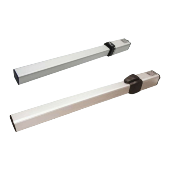
SEA MINI TANK Manual
Hydraulic operators for swing gates
Hide thumbs
Also See for MINI TANK:
- Installation manual (25 pages) ,
- Quick start manual (8 pages) ,
- Installation manual (12 pages)
Advertisement
Quick Links
ITALIANO
ENGLISH
FRANÇAIS
International registered trademark n. 804888
MINI TANK - HALF TANK
OPERATORI OLEODINAMICI PER CANCELLI A BATTENTE
HYDRAULIC OPERATORS FOR SWING GATES
OPERATEURS HYDRAULIQUES POUR PORTAILS A BATTANT
MINI TANK
HALF TANK
SEA
S.p.A.
Zona Industriale Sant'Atto - 64100 - Teramo - ITALY
Telephone: + 39 0 861 588341
www.seateam.com
67411170
REV. 14 - 05/2024
Advertisement

Summary of Contents for SEA MINI TANK
- Page 1 ITALIANO ENGLISH FRANÇAIS International registered trademark n. 804888 MINI TANK - HALF TANK OPERATORI OLEODINAMICI PER CANCELLI A BATTENTE HYDRAULIC OPERATORS FOR SWING GATES OPERATEURS HYDRAULIQUES POUR PORTAILS A BATTANT MINI TANK HALF TANK S.p.A. Zona Industriale Sant’Atto - 64100 - Teramo - ITALY Telephone: + 39 0 861 588341 www.seateam.com...
- Page 2 SB (without lock) Hydraulic locking is guaranteed on leaf length up to 1.80 m for MINI TANK and HALF TANK 270 and on leaf length up to 2.20 m for HALF TANK 390. All models are equipped with by-pass valves (for power...
- Page 3 Version with brake in opening and closing: + 50 mm to X and Y Version with brake in opening and closing: + 50 mm to X and Y The Max. opening of MINI TANK for PEDESTRIAN GATES is 95° ELECTRIC WIRINGS RECOMMENDED CABLES NUMBER AND SECTION...
- Page 4 ENGLISH International registered trademark n. 804888 MINI TANK WITH JOINT MINI TANK MINI TANK TECHNICAL DATA (230V) (120V) (230V) Power supply 120V (± 5%) 50/60 Hz 230V (± 5%) 50/60 Hz Absorbed power 180 W 240 W Absorbed current 2,45 A...
- Page 5 ENGLISH International registered trademark n. 804888 INWARD INSTALLATION OUTSIDE OUTSIDE INSIDE Fig. 7 INSIDE MINI TANK 270 mm - 250 mm TOTAL STROKE RECOMMENDED STROKE f ** STROKE OPENING STROKE INSTALL (mm) 90° (mm) (mm) (mm) (mm) (mm) (mm) (mm)
- Page 6 For the «c» dimension the reference is the minimum value that could be considered The «f» dimension has been calculated for a 40 mm thick INSIDE gate Fig. 10 MINI TANK - HALF TANK 270 HALF TANK 390 270 mm - 250 mm 390 mm - 370 mm...
- Page 7 ENGLISH International registered trademark n. 804888 INSTALLATION - PRELIMINARY NOTES Open the package carefully, making sure to not loose the parts listed in Fig. 3 For a proper operation, it is important to place as the operator as the front and rear brackets in a perfectly horizontal position with the help of a level, as shown in Fig.
- Page 8 ENGLISH International registered trademark n. 804888 FRONT BRACKET INSTALLATION Once the operator has been fixed on the rear bracket, close the leaf and proceed as follows: Unlock the operator by following the unlocking procedure shown in chapter 23 Pull out completely the chrome shaft, then bring it back about 1 cm Place the front bracket on the gate and place the shaft in the housing - Fig.
- Page 9 Hook the shaft on the front bracket (see the previous chapter) O ADJUST THE MECHANICAL STOP IN OPENING ACT ON PLATE O ADJUST THE MECHANICAL STOP IN CLOSING ACT ON PLATE MINI TANK MECHANICAL STOP KIT HALF TANK 270/390 MECHANICAL STOP KIT TWO RODS Fig. 28 Fig.
- Page 10 For future adjustments (for example in case of ELLOW periodic maintenance), being the release already installed, it will be necessary to proceed as indicated Fig. 33 below, according to the model in use. MINI TANK HALF TANK 270/390 Fig. 34 Fig. 35 PASS COVER...
- Page 11 ENGLISH International registered trademark n. 804888 PLASTIC RELEASE INSTALLATION for MINI TANK and HALF TANK - «PG» VERSION Assemble the plastic release as shown in Fig. 36. Fig. 36 Assemble the plastic release only at the end of the installation and after adjusting the by-pass valves.
- Page 12 ENGLISH International registered trademark n. 804888 EXTERNAL RELEASE INSTALLATION - ACCESSORY ON DEMAND Fig. 39 Fig. 40 CONNECTION OF THE RELEASE CABLE INSIDE THE OPERATOR Install the external release as shown in the images above - Fig. 39 and Fig. 40; For further information, consult the assembly instructions of the EXTERNAL RELEASE KIT BREATHER SCREW REMOVAL...
- Page 13 (rear and front brackets, swing fork) Check the correct operation and the conditions of all accessories, especially the safety devices ANNUAL Lubricate the shaft with SEA grease (GREASE GL 00 code 65000009) ANNUAL FTER THE MAINTENANCE IT IS NECESSARY TO REPEAT THE AUTOMATION TESTING AND COMMISSIONING...
- Page 14 14. Transit through the leaves is allowed only when the gate is fully open. 15. The User must not attempt to repair or to take direct action on the system and must solely contact qualified SEA personnel or SEA service centers. The User can apply only the manual function of emergency.
-
Page 15: Declaration Of Conformity
La SEA S.p.A. dichiara sotto la propria responsabilità e, se applicabile, del suo rappresentante autorizzato che, con l’installazione degli adeguati dispositivi di sicurezza e di filtraggio disturbi, i prodotti:... - Page 16 International registered trademark n. 804888 S.p.A. Zona Industriale Sant’Atto - 64100 - Teramo - ITALY Telephone: + 39 0 861 588341 www.seateam.com...


Need help?
Do you have a question about the MINI TANK and is the answer not in the manual?
Questions and answers