Table of Contents
Advertisement
International registered trademark n. 2.777.971
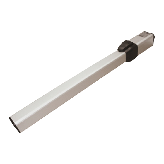
LIBRA
NEW MINI TANK
HALF TANK
FULL TANK
INSTALLATION MANUALS
AND SAFETY INFORMATION
SEA USA Inc.
10850 N.W. 21st unit 160 DORAL MIAMI
Florida (FL) 33172 USA
Phone:++1-305.594.1151 Fax: ++1-305.594.7325
Toll Free: 800.689.4716
web site: www.sea-usa.com
e-mail: sales@sea-usa.com
67410246
REV 11 - 09/2018
Advertisement
Table of Contents

Related Manuals for SEA LIBRA Series


Summary of Contents for SEA LIBRA Series
- Page 1 International registered trademark n. 2.777.971 LIBRA NEW MINI TANK HALF TANK FULL TANK INSTALLATION MANUALS AND SAFETY INFORMATION SEA USA Inc. 10850 N.W. 21st unit 160 DORAL MIAMI Florida (FL) 33172 USA Phone:++1-305.594.1151 Fax: ++1-305.594.7325 Toll Free: 800.689.4716 web site: www.sea-usa.com e-mail: sales@sea-usa.com...
-
Page 2: Important Safety Information
International registered trademark n. 2.777.971 IMPORTANT SAFETY INFORMATION GENERAL SAFETY PRECAUTIONS The following precautions are an integral and essential part of the product and must be supplied to the user Read them carefully as they contain important indications for the safe installation, use and maintenance. 1. -
Page 3: General Safety Information
International registered trademark n. 2.777.971 GENERAL SAFETY INFORMATION An appliance shall be provided with an instruction manual. The instruction manual shall give instructions for the installation, operation, and user maintenance of the appliance. The installation instructions shall specify the need for a grounding-type receptacle for connection to the supply and shall stress the importance of proper grounding. - Page 4 The installer shall follow the provided instructions thoroughly. SEA products must only be used to automate doors, gates and wings. Any initiative taken without SEA USA Inc. explicit authorization will preserve the manufacturer from whatsoever responsibility.
-
Page 5: Entrapment Protection
International registered trademark n. 2.777.971 5. The End of Type E. Type E (audible alarm) devices can no longer be used for entrapment protection. This change was made because the Type E device is really a warning device, not an entrapment-protection device. Also, all gate operator classes are now required to have an audio alarm that sounds when two successive obstructions are encountered via a contact-type system. -
Page 6: Gate Warnings
Fig. 4 PRECAUTIONS SEA motors have been created for the automation of gates used by vehicles only. Be aware to avoid the crossing of the gate path because it is very dangerous for pedestrians (fig. 4). Install the warning signs, on each side of the gate and in avisible zone which informs the pedestrians about the danger they run when passing or resting in the environment of the gate (fig. -
Page 7: Features And Specifications
FEATURES AND SPECIFICATIONS NEW MINI TANK: high quality hydraulic operator; residential use; max. leaf length: 9,84 feet; Available in 2 models: SC up to 5,9 feet, with lock in closing (for leaf length over 5,9 feet use the electric-lock) SB up to 9,84 feet, without lock (the use of the electric-lock is obligatory on SB version) Equipped with by-pass valves for torque regulation. -
Page 8: Technical Features
DESCRIPTION NEW MINI TANK HALF TANK FULL TANK Shaft cover Release Front bracket Rear bracket Cylinder Electric motor By-pass valves Exit electric cables Fig. 9 Hydraulic pump Fig. 10 NEW MINI TANK HALF TANK FULL TANK TECHNICAL FEATURES HALF TANK LARGE FULL TANK LARGE Power supply 120V (60Hz) Power... - Page 9 FULL TANK Fig. 11...
- Page 10 HALF TANK Fig. 12...
- Page 11 NEW MINI TANK Fig. 13...
-
Page 12: Typical Installation
TYPICAL INSTALLATION 1) Operator 2) Mechanical stop 3) Electronic control unit Fig. 14 4) Flashing lamp 5) Photocell Dx 6) Differential switch 7) Photocell Sx 8) Start - stop push button with key 9) Antenna 10) Support for photocells with photocells 11) Warning notice TYPE OF INSTALLATION It’s possible to install Libra with opening inside (Fig. - Page 13 INWARD INSTALLATION outside Fig. 17 inside...
- Page 14 MINI TANK & HALF TANK/ FULL TANK (Fig. 17) total stroke 10.63 inches - max suggested stroke 9,84 inches Max opening Max stroke Stroke for 90° inches inches inches Angle° (inches) (inches) 1.96 3.93 4.52 110° 9.84 8.46 5.90 3.93 1.96 90°...
- Page 15 OUTWARD INSTALLATION outside inside Fig. 18...
- Page 16 MINI TANK & HALF TANK/ FULL TANK (Fig.18) total stroke 10.63 inches - max suggested stroke 9,84 inches Max opening Max stroke Stroke for 90° inches inches Angle° (inches) (inches) 5.90 3.54 95° 9.84 9.44 6.29 3.54 90° 9.84 6.49 3.14 95°...
-
Page 17: Mechanical Installation
MECHANICAL INSTALLATION PRELIMINARY -Open carefully the package, being sure not to loose parts. Parts are listed in Fig. 11-12-13 -Attach the rear oscillating bracket as shown in Fig. 19 -Attach the spheric joint as shown in Fig. 20 and 21 -Start positioning the rear bracket as specified on following pages Rear oscillating bracket installation Fig. - Page 18 INSTALLATION OF THE REAR BRACKET TO THE POST The bracket must be positioned so that the operator is perfectly leveled (Fig. 23) Adjustable rear bracket (with screws) on demand 2.16” Fig. 22 Fig. 23 POSITIONING OF THE FRONT FIXATION Once the operator has been mounted on the back fixation close the leaf and do as follows: 1) Release the operator (as in Fig.
- Page 19 WELDING OF THE FRONT BRACKET TO THE GATE The bracket must be positioned so that the operator is perfectly leveled. NOTE: If the brackets are installed before the operator, place the front bracket ½ inch lower than the rear bracket (Fig. 26) ½...
- Page 20 INSTALLATION OF THE MINI TANK MECHANICAL LIMIT SWITCH STOPS (Accessories on request) - Release the unit (as in Fig. 56 to 61). - Let the rod come out about 3/4 of its run. - Put the limit switch stops on the front flange of the unit with the two rods (of the three which are present on the stop) which are in parallel to the gate (Fig.
- Page 21 INSTALLATION OF THE HALF TANK MECHANICAL LIMIT SWITCH STOPS (Accessories on request) 1) Release the unit (as in Fig. 56 to 61) 2) Let the rod come out about 3/4 of its run 3) Put the limit switch stops on the front flange of the unit with the two rods (of the three which are present on the stop) which are in parallel to the gate (Fig.
- Page 22 Ve r y I m p o r t a n t f o r H A L F TA N K a n d F U L L TA N K : make sure that the two discs A and B perfeclty fit in opening phase Fig.
-
Page 23: Torque Adjustment (By-Pass Valve)
TORQUE ADJUSTMENT (By-Pass Valve) In case of first installation both, the cover of the release and the cover of the by pass valves must not yet be inserted. In this case refer to Fig. 38 and Fig. 40. Should the by-pass valves adjustment be made in a second moment, because of periodical maintenance or other, take off the screw which locks the by-pass cover (Fig. - Page 24 PLASTIC RELEASE MOUNTING (HALF TANK - MINI TANK) ATTENTION: the mounting of the plastic release must be effectuated as shown in Fig. 42 only and exsclusively after having Mechanic lock of the finished all the installation operations, release by-pass cover mounting of the rod cover and calibration of the by-pass valves A T T E N T I O N :...
-
Page 25: Installation On Masonry Pillars, Making A Niche
RELEASE MOUNTING (FULL TANK) Fig. 48 Fig. 47 Remove the transporting plate as shown in Fig. 47 Mount the release as shown in Fig. 48 INSTALLATION ON MASONRY PILLARS, MAKING A NICHE 7,08’’ 2,16 * 46,45’’ 2,36’’ ** 55,70’’ Min. 6,10’’... -
Page 26: Installation Of The Chromium-Plated Rod Protection
HYDRAULIC SLOW-DOWN ADJUSTMENT (ONLY LIBRA FULL TANK STANDARD) The hydraulic slow-down will take effect in the last 10 - 15 degrees of the closing process. Slow-Down Adjustment: Take out manual release as in Fig. 50 The slow-down is adjustable by rotating the screw for the brake regulation Rotating clockwise: Increase the effect of the slow-down Rotating Anti’clockwise: Decrease the the effect of the slow-down REMEMBER to check the correct setting of electronic slow-down... - Page 27 OIL LEVEL MEASUREMENT (HALF TANK - NEW MINI TANK) 2.16” Insertion into 3.34” the motor (in.) 3.34” Fig. 53 OIL LEVEL MEASUREMENT (FULL TANK) Oil level Fig. 54...
-
Page 28: Libra Accessories
11) Check the tight of the hardware of the gate 12) Check the operating of all accessories, especially the functioning of all safety devices and Position Gate (if installed) 13) Lubricate the shaft with SEA grease (GREASE GL 00 65000009) - Page 29 Turn the key anti-clockwise to tighten the lid, remove the key and close the lock cover. Fig. 58 Fig. 59 SEA recommend to the end user to release the operator only in case of power failure. Always contact the professional installer in case of not correct working of the operators.
- Page 30 To the attention of users and technicians HALF TANK - NEW MINI TANK MANUAL RELEASE SYSTEM To release operate as follows: -Insert the key and turn it about 180° anti-clockwise (Fig. 60-61) To relock the operator do as follows: -Insert the key and turn it clockwise until it stops (Fig. 60-61) Attention: To release cut current supply PLASTIC RELEASE SYSTEM (HALF TANK - NEW MINI TANK) Lock...
- Page 31 PAYMENT: Method of payments and terms are notified by SEA and displayed on the commercial invoice. DELIVERY: The delivery time on the invoice is not binding and represents an estimated delivery. Shipments costs will be charged to the buyer and SEA is not responsible for delays and/or damages occurred to the products during shipment.
- Page 32 International registered trademark n. 2.777.971 SEA USA Inc. 10850 N.W. 21st unit 160 DORAL MIAMI Florida (FL) 33172 USA Phone:++1-305.594.1151 Fax: ++1-305.594.7325 Toll Free: 800.689.4716 web site: www.sea-usa.com e-mail: sales@sea-usa.com...
Need help?
Do you have a question about the LIBRA Series and is the answer not in the manual?
Questions and answers