
Related Manuals for Ariston NIMBUS LB M R32


Summarization of Contents
Safety Advices
General Warnings and Safety Instructions
Important warnings for safe installation, use, and maintenance of the product.
Use of the R32 Refrigerant
Information on R32 refrigerant, flammability, and safe handling procedures.
Symbols Affixed to the Appliance
Explanation of symbols found on the outdoor unit (ODU) and their meanings.
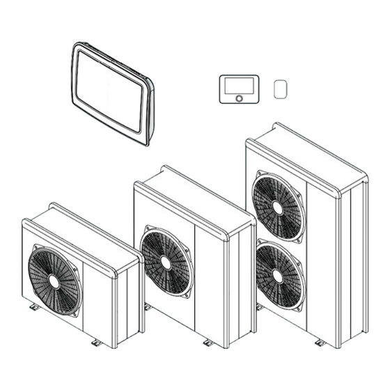
Description of the System
Outdoor Unit (ODU) Structure
Details the components and models of the outdoor unit (ODU).
Outdoor Unit Dimensions and Weights
Provides dimensions and weight specifications for various outdoor unit models.
Hydraulic and Drainage Fittings
Details the hydraulic and drainage connection points on the outdoor unit.
Outdoor Unit Accessories
Lists optional accessories available for the outdoor unit.
Indoor Unit (IDU) Dimensions and Weights
Provides dimensions and weight specifications for the indoor unit (IDU).
Operational Limits
Diagrams showing operating limits for space heating and cooling.
Compressor Frequency Table
Table detailing compressor frequency limits based on outdoor temperature.
Identification
Explains how to identify outdoor units via the product identification plate.
System Interface SENSYS HD Description
Overview of the SENSYS HD system interface and its buttons/icons.
System Interface Technical Data
Provides technical specifications for the SENSYS HD system interface.
External Probe Installation
Instructions for installing and connecting the external probe.
Installation
Preliminary Warnings
Crucial warnings and guidelines for qualified personnel installing the appliance.
Receiving the Product
Instructions for checking product contents and handling upon delivery.
Outdoor Unit Installation Place
Guidelines for selecting a suitable outdoor installation location.
Outdoor Unit Noise Level
Recommendations for minimizing noise pollution from the outdoor unit.
Outdoor Unit Handling
Safety precautions for handling the outdoor unit during installation.
Outdoor Unit Installation
Instructions for anchoring the outdoor unit to the floor or a bracket.
Arranging Outdoor Unit Connections
Guidance on arranging cables and using cable grommets.
Installing Accessory Kit
Instructions for installing anti-freeze kit and condensate tray.
Condensate Collection Tray Heating Element
Steps for positioning and connecting the heating element for the condensate tray.
Indoor Unit Installation Place
Guidelines for selecting a suitable indoor installation location.
Hanging the Indoor Unit
Instructions for mounting the indoor unit bracket and hanging the unit.
Hydraulic Connections
Minimum Water Content
Specifies minimum water content requirement for system operation.
Expansion Vessel
Information on the expansion vessel and installer responsibility for sizing.
Rated and Minimum Flow Rate
Table showing nominal and minimum flow rates for different models.
Available Pressure
Explains available pressure curves and recommendations for circulator pumps/by-pass.
Characteristics of the Supply Water
Guidelines on water hardness, conductivity, pH, and glycol use.
Filling the System
Instructions for filling the system, purging air, and checking pressure.
Schematic Hydraulic Diagram Example
Provides schematic diagrams of hydraulic connections for the system.
Note: Under-floor System Installations
Specific considerations for under-floor heating installations and safety devices.
Electrical Connections
General Warnings for Electrical Connections
Safety warnings and general guidelines for electrical connections.
Cable Sizing and Power Supply Tables
Table detailing cable cross-sections and power supply requirements for units.
Outdoor Unit Electrical Connections
Terminal board diagrams and connection points for the outdoor unit.
Indoor Unit Electrical Connections
Power supply and signal connection diagrams for the indoor unit.
Indoor to Outdoor Unit Electrical Connection Example
Schematic showing the electrical connection between indoor and outdoor units.
System Interface Wall Installation
Instructions for mounting and connecting the SENSYS HD system interface to the wall.
Commissioning
Electrical and Gas Leakage Checks
Procedures for checking electrical safety, earth resistance, and dispersions.
Gas Leakage Checks
Instructions for checking for refrigerant gas leakages.
Preliminary Checks
Pre-installation checks for both outdoor and indoor units.
Initial Start-up Safety
Safety requirements and procedure for the initial start-up of the system interface.
Start-up Procedure
Step-by-step guide for configuring the system interface during initial start-up.
Basic System Interface Functions
Explanation of the system interface's functions as a thermostat and monitoring device.
Manual Temperature Adjustment
How to manually adjust room temperature settings on the interface.
Programmed Mode Temperature Adjustment
Temporary adjustment of room temperature in programmed mode.
AUTO Function Temperature Adjustment
Adjusting room temperature using AUTO function for heating settings.
Accessing the Technical Area
Procedure to access the technical area of the system interface.
Technical Parameters Overview
Overview of accessing and navigating technical parameters.
Complete Menu Navigation
Accessing and navigating the complete menu structure.
Thermoregulation Settings
Parameter for configuring thermoregulation settings.
HV Input 1 Configuration
Configuration of High Voltage input 1 for various functions.
HV Input 2 Configuration
Configuration of High Voltage input 2 for various functions.
Auxiliary Input 1 Configuration
Configuration of Auxiliary input 1 for sensors or external controls.
Auxiliary Input 2 Configuration
Configuration of Auxiliary input 2 for sensors or external controls.
Electric Heat Sources Blocking Type
Configuration for blocking electric heat sources based on energy provider signals.
CH Press Detection Device Setting
Setting for the central heating pressure detection device.
System Flow Temperature Selection
Selection of water flow temperature measurement method.
Humidity Input Zone Definition
Defines zones for humidity reading by the Energy Manager.
Auxiliary Output 1 Configuration
Configuration of Auxiliary output 1 for fault alarms or external requests.
Auxiliary Output 2 Configuration
Configuration of Auxiliary output 2 for fault alarms or external requests.
Auxiliary Output 3 Configuration
Configuration of Auxiliary output 3 for fault alarms or external requests.
Auxiliary Output 4 Configuration
Configuration of Auxiliary output 4 for fault alarms or external requests.
Auxiliary P2 Circulator Setting
Setting for the auxiliary circulator (P2) operation.
Pro-Tech Anode Activation
Activation of the Pro-Tech anode for DHW tank.
CH Secondary Heat Source Activation Logic
Logic for activating auxiliary heat sources for central heating.
ECO / COMFORT Settings
Defines delay for integration heating elements based on economy/comfort.
Delay Timer for Integration Sources
Defines delay for integration sources when ECO/COMFORT is customizable.
Release Integral Threshold
Threshold for release integral used by energy manager.
Reset Integral Threshold
Threshold for reset integral used by energy manager.
DHW Secondary Heat Source Activation Logic
Logic for activating auxiliary heat sources for DHW.
DHW Integration Delay Timer
Time for starting DHW integration calculation.
DHW Integration Release Threshold
Activation threshold for DHW integration.
Tank Electric Heater Operation
Operating logic for the integration heating element in the DHW calorifier.
DHW High Priority Temperature Threshold
DHW calorifier temp threshold for heating element activation.
Energy Manager Parameter 1 Settings
Boiler and heat pump disabling settings based on outdoor temperature.
External Temperature Correction
Compensation for external sensor temperature reading.
Water Circulation Settings
Central heating pump prerun time, overrun, and speed control.
Antifreeze HP Circulator Control
Setting circulation pump speed during heat pump anti-frost cycle.
Heating Cycle Boost Time
Delay for increasing water delivery set-point in AUTO heating mode.
Flow Temperature Offset for Heating
Offset for heat pump delivery set-point to compensate heat losses.
Cooling Mode Activation
Activation setting for cooling mode.
Flow Temperature Offset for Cooling
Offset for heat pump delivery set-point in cooling mode.
Humidity Control Threshold
Sets the threshold for humidity control.
Humidity Control Hysteresis
Sets the hysteresis for humidity control.
DHW Comfort Setpoint Temperature
Defines the comfort set-point temperature for domestic hot water.
DHW Reduced Setpoint Temperature
Defines the reduced set-point temperature for domestic hot water.
Comfort Function Configuration
Configures domestic hot water production mode (Disabled, Timer, Active).
DHW Operation Mode
Sets the DHW operation mode (Standard, Green, HC-HP, HC-HP 40).
Maximum Heat Pump Charging Time
Defines heat pump charging time before auxiliary sources activate.
Thermal Cleanse Function
Activates the thermal cleanse function for DHW calorifier at 60°C.
Thermal Cleanse Start Time
Defines the start time for the DHW tank sanitisation function.
Thermal Cleanse Cycle Frequency
Sets the frequency for repeating the DHW tank sanitisation function.
Manual Mode 1 Activation
Manual activation of system components like pumps and valves.
Heat Pump Circulator Control
Control setting for the heat pump circulator (off, low, high speed).
Diverter Valve Control
Control setting for the diverter valve (DHW or heating cycle).
Diverter Valve Cooling Control
Control setting for the diverter valve in cooling mode.
Auxiliary Circulator Control
Control setting for the auxiliary circulator.
All Output Auxiliary Contact Control
Control for all auxiliary outputs.
Manual Mode 2 Activation
Manual activation of system components (pumps, valves, elements).
Force Heat Pump in Heating Mode
Activates the heat pump in heating mode.
Force Heat Pump in Cooling Mode
Activates the heat pump in cooling mode.
Tank Electric Heater Activation
Activates the heating element immersed in the calorifier in DHW mode.
Air-Purge Function
Activates system deaeration for up to 18 minutes.
Antiblocking Function Enable
Activates the anti-lock function for the primary circulation pump.
Quiet Mode Activation for Heat Pump
Activates quiet mode for the heat pump, reducing noise level.
Quiet Mode Start Time
Sets the start time for the heat pump quiet mode.
Quiet Mode End Time
Sets the end time for the heat pump quiet mode.
Floor Drying Cycle Programs
Defines screed drying programs for under-floor systems.
Floor Drying Flow Set Point Temperature
Defines the set-point temperature for heating delivery during screed drying.
Floor Drying Total Remaining Days
Defines the remaining days for the screed drying function.
Exogel Kit Activation
Enables integration of the anti-freeze kit.
Energy Manager Statistics
Shows the duration of system operation in hours.
Energy Manager Status Diagnostics
Displays the current status of the Energy Manager.
Hydraulic Scheme Diagnostics
Diagnostic tool for checking the hydraulic scheme configuration.
Central Heating Flow Set Temperature
Displays the central heating flow set temperature.
Central Heating Flow Temperature
Displays the current central heating flow temperature.
DHW Storage Temperature
Displays the domestic hot water storage temperature.
Room Thermostat 1 Diagnostics
Displays status of Room Thermostat 1.
Room Thermostat 2 Diagnostics
Displays status of Room Thermostat 2.
Auxiliary Input 1 Status
Displays status of Auxiliary input 1 (Open/Close).
Auxiliary Input 2 Status
Displays status of Auxiliary input 2 (Open/Close).
HV Input 1 Status
Displays status of High Voltage input 1 (OFF/ON).
HV Input 2 Status
Displays status of High Voltage input 2 (OFF/ON).
System Output Diagnostics
Displays the values of the system's board outputs.
Central Heating Circulator Status
Displays the status of the central heating circulator.
Tank Electric Heater Status
Displays the status of the tank electric heater.
Heat Pump Circulator 2 Status
Displays the status of the heat pump circulator 2.
Diverter Valve (CH/DHW) Status
Displays the status of the diverter valve for CH/DHW.
Diverter Valve 2 (CH/Cooling) Status
Displays the status of the diverter valve for CH/Cooling.
Auxiliary Output 1 Status
Displays the status of Auxiliary output 1 (Open/Close).
Auxiliary Output 2 Status
Displays the status of Auxiliary output 2 (Open/Close).
Software Version
Displays the main software version.
System Integration Settings
PV offset for DHW setpoint during integration.
Tank Solar Integration
Activates integration of the solar heating system.
OpenTherm Gateway Activation
Activates the OpenTherm gateway.
Error History Log
Displays the last 10 recorded errors.
Reset Error List
Procedure to reset the error list.
Reset Factory Settings
Restores the system to its default factory settings.
Thermal Cleanse Target Temperature
Defines the setpoint for the thermal cleanse cycle.
Antilegionella Target Temperature Duration
Defines the duration for maintaining the thermal cleanse target temp.
Maximum Antilegionella Duration
Defines the maximum time for completing the thermal cleanse cycle.
Energy Pulse Unit Setting
Defines the unit for energy pulse measurement (kWh or m3).
Energy Pulse Value Number
Defines the energy pulse value number.
Energy Pulse Value Factor
Defines the energy pulse value factor for calculating kWh.
Energy Pulse Measuring Type
Defines how HP consumption is measured (HP only or HP+Heater).
Tank Electric Heaters Nominal Power
Specifies the nominal power consumption of tank electric heaters.
Tank Electric Heaters Efficiency
Specifies the nominal efficiency of tank electric heaters.
Zone 1 Parameters - Setpoint
Defines setpoints for Zone 1 (T Day, T Night, Z1 set, frost temp).
Automatic Winter Mode Activation
Activates or deactivates the automatic winter mode.
Automatic Winter Mode Threshold
Sets the threshold for automatic summer/winter switching delay.
Automatic Winter Mode Delay Time
Sets the delay time for automatic summer/winter switching.
Setup - Zone Temperature Range
Sets the temperature range for zones (Low or High Temp).
Thermoregulation Configuration
Configures thermoregulation (Fix Flow T, Basic, Room T, Outdoor T).
Slope Adjustment
Sets the heating curve slope for temperature adjustment.
Parallel Shift Adjustment
Adjusts the heating curve by a parallel shift.
Room Influence Proportional Adjustment
Adjusts room sensor influence on delivery temperature calculation.
Maximum Temperature Setting
Sets the maximum temperature value.
Minimum Temperature Setting
Sets the minimum temperature value.
Thermoregulation Logic Selection
Selects the thermoregulation logic (Classic or Smart).
Quick Night Setback
Activates or deactivates the quick night setback.
Heat Request Mode
Defines the heat request mode (Standard, RT exclusion, Forcing Heat Demand).
Room Temperature Diagnostics
Displays the room temperature.
Room Temperature Setpoint Diagnostics
Displays the room temperature setpoint.
Flow Temperature Diagnostics
Displays the flow temperature.
Return Temperature Diagnostics
Displays the return temperature.
Heat Request Zone 2 Diagnostics
Displays the heat request status for Zone 2.
Pump Status Diagnostics
Displays the status of the pumps (OFF/ON).
Relative Humidity Diagnostics
Displays the relative humidity.
Zone Flow Temperature Setpoint Diagnostics
Displays the zone flow temperature setpoint.
Zone Module Settings - Pump Modulation
Sets the zone pump modulation (Fixed, DeltaT, Pressure).
Target DeltaT for Pump Modulation
Sets the target deltaT for pump modulation.
Pump Fixed Speed Setting
Sets the pump speed to a fixed value.
Cooling Settings
Cooling settings section.
Cooling Setpoint Temperature
Sets the cooling setpoint temperature.
Cooling Temperature Range
Sets the cooling temperature range (Fan Coil or Underfloor).
Cooling Thermoregulation
Configures cooling thermoregulation (ON/OFF, Fix Flow T, Outdoor T).
Cooling Slope Adjustment
Sets the cooling curve slope.
Cooling Parallel Shift
Adjusts the cooling curve by a parallel shift.
Maximum Cooling Temperature
Sets the maximum cooling temperature.
Minimum Cooling Temperature
Sets the minimum cooling temperature.
Target DeltaT for Cooling Pump Modulation
Sets the target deltaT for pump modulation in cooling.
Zone Regulation Parameters - Heating Type
Selects the heating type (Floor, Radiators, Convection, Air Heating).
Room Influence Setting
Adjusts room influence on heating settings (OFF, Less, Medium, More).
Building Isolation Level
Sets the building isolation level (Poor, Average, Good).
Building Size Setting
Sets the building size (Small, Medium, Large).
Climatic Zone Setting
Sets the climatic zone for system configuration.
Auto Slope Adaptation
Activates automatic adjustment of the slope.
Advanced Settings - Heating Controller
Configures the heating controller (None, Room thermostat, Room Sensor).
Advanced Settings - Cooling Controller
Configures the cooling controller (None, Room thermostat, Room Sensor).
Humidity Control Threshold
Sets the threshold for humidity control.
Humidity Control Hysteresis
Sets the hysteresis for humidity control.
Humidity Control Setting
Sets the humidity control level (None, Stop).
Zone 2 Parameters - Setpoint
Defines setpoints for Zone 2 (T Day, T Night, Z2 set, frost temp).
Zone 2 Day Setpoint Temperature
Sets the day setpoint temperature for Zone 2.
Zone 2 Night Setpoint Temperature
Sets the night setpoint temperature for Zone 2.
Zone 2 Target Setpoint Temperature
Sets the target temperature for Zone 2.
Zone 2 Frost Protection Temperature
Sets the frost protection temperature for Zone 2.
Automatic Winter Mode Activation for Zone 2
Activates or deactivates automatic winter mode for Zone 2.
Automatic Winter Mode Threshold (Zone 2)
Sets the threshold for automatic winter mode switching for Zone 2.
Automatic Winter Mode Delay Time (Zone 2)
Sets the delay time for automatic winter mode switching for Zone 2.
Setup - Zone Temperature Range (Zone 2)
Sets the temperature range for Zone 2 (Low or High Temp).
Thermoregulation Configuration (Zone 2)
Configures thermoregulation for Zone 2 (Fix Flow T, Basic, Room T, Outdoor T).
Slope Adjustment (Zone 2)
Sets the heating curve slope for Zone 2.
Parallel Shift Adjustment (Zone 2)
Adjusts the heating curve by a parallel shift for Zone 2.
Room Influence Proportional (Zone 2)
Adjusts room sensor influence on heating temperature calculation for Zone 2.
Maximum Temperature Setting (Zone 2)
Sets the maximum temperature for Zone 2.
Minimum Temperature Setting (Zone 2)
Sets the minimum temperature for Zone 2.
Thermoregulation Logic Selection (Zone 2)
Selects the thermoregulation logic (Classic or Smart) for Zone 2.
Quick Night Setback (Zone 2)
Activates or deactivates quick night setback for Zone 2.
Heat Request Mode (Zone 2)
Defines the heat request mode for Zone 2.
Room Temperature Diagnostics (Zone 2)
Displays the room temperature for Zone 2.
Room Temperature Setpoint Diagnostics (Zone 2)
Displays the room temperature setpoint for Zone 2.
Flow Temperature Diagnostics (Zone 2)
Displays the flow temperature for Zone 2.
Return Temperature Diagnostics (Zone 2)
Displays the return temperature for Zone 2.
Heat Request Z2 Diagnostics
Displays the heat request status for Zone 2.
Pump Status Diagnostics (Zone 2)
Displays the status of the pumps for Zone 2 (OFF/ON).
Relative Humidity Diagnostics (Zone 2)
Displays the relative humidity for Zone 2.
Zone Flow Temperature Setpoint Diagnostics (Zone 2)
Displays the zone flow temperature setpoint for Zone 2.
Zone Module Settings - Pump Modulation (Zone 2)
Sets the zone 2 pump modulation (Fixed, DeltaT, Pressure).
Target DeltaT for Pump Modulation (Zone 2)
Sets the target deltaT for pump modulation for Zone 2.
Pump Fixed Speed Setting (Zone 2)
Sets the pump speed to a fixed value for Zone 2.
Cooling Settings (Zone 2)
Cooling settings section for Zone 2.
Cooling Setpoint Temperature (Zone 2)
Sets the cooling setpoint temperature for Zone 2.
Cooling Temperature Range (Zone 2)
Sets the cooling temperature range for Zone 2.
Cooling Thermoregulation (Zone 2)
Configures cooling thermoregulation for Zone 2.
Cooling Slope Adjustment (Zone 2)
Sets the cooling curve slope for Zone 2.
Cooling Parallel Shift (Zone 2)
Adjusts the cooling curve by a parallel shift for Zone 2.
Maximum Cooling Temperature (Zone 2)
Sets the maximum cooling temperature for Zone 2.
Minimum Cooling Temperature (Zone 2)
Sets the minimum cooling temperature for Zone 2.
Target DeltaT for Cooling Pump Modulation (Zone 2)
Sets the target deltaT for pump modulation in cooling for Zone 2.
Zone Regulation Parameters - Heating Type (Zone 2)
Selects the heating type for Zone 2.
Room Influence Setting (Zone 2)
Adjusts room influence on heating settings for Zone 2.
Building Isolation Level (Zone 2)
Sets the building isolation level for Zone 2.
Building Size Setting (Zone 2)
Sets the building size for Zone 2.
Climatic Zone Setting (Zone 2)
Sets the climatic zone for Zone 2 system configuration.
Auto Slope Adaptation (Zone 2)
Activates automatic adjustment of the slope for Zone 2.
Advanced Settings - Heating Controller (Zone 2)
Configures the heating controller for Zone 2.
Advanced Settings - Cooling Controller (Zone 2)
Configures the cooling controller for Zone 2.
Humidity Control Threshold (Zone 2)
Sets the threshold for humidity control for Zone 2.
Humidity Control Hysteresis (Zone 2)
Sets the hysteresis for humidity control for Zone 2.
Humidity Control Setting (Zone 2)
Sets the humidity control level for Zone 2.
Standard SG Ready Function
Explains the SG ready function activation and configurations.
Service
User Information for System Operation
Information for the user on system operation and keeping the manual accessible.
Indoor Unit Anti-freeze Function
Warning regarding the indoor unit's integrated heating elements.
Outdoor Unit Anti-freeze Function
Explains the operation of the outdoor unit's primary circulation pump.
Indoor Unit Cleaning and Inspection
Annual checks for the indoor unit, including hydraulic system and safety checks.
Fuse Replacement Warning
Warning against using incorrect fuse replacements due to fire risk.
Outdoor Unit Cleaning and Inspection
Annual checks for the outdoor unit, including refrigerant gas seal and cleaning.
Manufacturer Specification for Replacement Parts
Emphasizes using only manufacturer-specified replacement parts.
Working with Intrinsically Safe Components
Guideline on working with intrinsically safe components in flammable atmospheres.
Annual Maintenance Checklist
General checklist for annual maintenance of the system.
Outdoor Unit Heat Exchanger Maintenance
Check and clean the outdoor unit's heat exchanger for obstructions.
Outdoor Unit Front Grille Maintenance
Check and clean the outdoor unit's front grille for obstructions.
Plumbing Connection Inspection
Inspect plumbing connections for leakages and replace seals if needed.
Water Pressure Check
Check the system's water pressure within the specified range.
Expansion Vessel Check
Check and replenish the expansion vessel's pre-charge pressure.
Water Filter Cleaning
Clean the water filter to remove residues.
Safety Valve Discharge Pipe Check
Check the positioning of the safety valve discharge pipe.
Outdoor Unit Noise and Vibration Check
Check for and address abnormal noises or vibrations from the outdoor unit.
Automatic Deaeration Function
Function for removing air from the hydraulic circuit.
Electrical Connections Annual Maintenance
Annual checks for electrical panels, cabling, and voltage/absorption.
Domestic Hot Water Tank Annual Maintenance
Annual checks for the domestic hot water storage tank, including limescale removal.
Risk of Freezing Prevention
Precautions for preventing freezing of the tank.
External Parts Cleaning
Instructions for cleaning the external parts of the appliance.
Ventilated Area Safety for Hot Work
Safety warning for working in ventilated areas before hot work.
Indoor Unit Cleaning and Inspection Procedures
Annual checks for the indoor unit, including hydraulic system and safety checks.
Outdoor Unit Cleaning and Inspection Procedures
Annual checks for the outdoor unit, including refrigerant gas seal and cleaning.
Indoor Unit Error List
Explains how errors are displayed and lists indoor unit errors with resolutions.
Outdoor Unit Error Codes
Lists various fault codes for the outdoor unit and their reset types.
Inverter Error Codes
Lists inverter error codes and their presence for different Nimbus EXT R32 models.
Decommissioning
Draining Circuit and Recovering Refrigerant
Procedure for safely recovering refrigerant from the system.
Decommissioned Equipment Labelling
Requirement for labelling decommissioned equipment with refrigerant status.
Disposal of Electrical and Electronic Equipment
Guidelines for the correct disposal of electrical and electronic equipment (WEEE).
Professional WEEE Definition
Definition and content of professional WEEE.
Household WEEE Definition
Definition of WEEE deriving from households.
Technical Information
Data Plate Information
Explains the information found on the indoor and outdoor unit data plates.
Refrigerant Technical Data
Table showing refrigerant type, charge, GWP, and CO2 equivalent for models.
Need help?
Do you have a question about the NIMBUS LB M R32 and is the answer not in the manual?
Questions and answers