
Related Manuals for Ariston NIMBUS POCKET 40 M EXT NET


Summary of Contents for Ariston NIMBUS POCKET 40 M EXT NET
- Page 1 NIMBUS POCKET M NET 3319105 ISTRUZIONI TECNICHE PER L’INSTALLAZIONE E LA MANUTENZIONE TECHNICAL INSTRUCTIONS FOR INSTALLATION AND MAINTENANCE 420000454000...
-
Page 2: Table Of Contents
INDICE Collegamenti elettrici Circuito elettrico ..................18 Generalità Tabelle collegamenti elettrci ............... 18 Norme di sicurezza ...................3 Connessioni elettriche dell’unità esterna ........19 Caratteristiche dell’acqua provvista all’impianto ......6 Connessioni elettriche dell’unità interna ........20 Connessioni elettriche tra unità interna ed unità esterna ..21 Descrizione del sistema Schema elettrico - Quadro unità... -
Page 3: Norme Di Sicurezza
NORME DI SICUREZZA non soggetta a vibrazioni. Rumorosità durante il funzionamento. ATTENZIONE Non danneggiare, nel forare la parete, seguente manuale costituisce parte cavi elettrici o tubazioni preesistenti. integrante ed essenziale del prodotto. Deve Folgorazione per contatto con conduttori essere conservato con cura e deve sempre sotto tensione. - Page 4 o alternativo siano correttamente fi ssate), protezioni e con la dovuta cautela. utilizzarle correttamente, non intralciare Danneggiamento dell’apparecchio o di i passaggi con il cavo di alimentazione, oggetti circostanti per urti, colpi, incisioni, assicurarle da eventuale caduta dall’alto, schiacciamento. scollegarle e riporle dopo l’uso. Lesioni personali per proiezione di scheg- Indossare, durante le lavorazioni, gli indu- ge o frammenti, inalazione polveri, urti, tagli,...
- Page 5 stione di agenti chimici nocivi. ATTENZIONE! Danneggiamento dell’apparecchio o di og- L’apparecchio può essere utilizzato da bambinni getti circostanti per corrosione da sostanze di età non inferiore a 8 anni e da persone con acide. ridotte capacità fi siche, sensoriali o mentali, o prive di esperienza o della necessaria conos- Nel caso si avverta odore di bruciato o si cenza, purché...
-
Page 6: Caratteristiche Dell'acqua Provvista All'impianto
Marcatura CE Pulizia dell’impianto L’apposizione della marcatura CE sull’apparecchio ne at- In occasione della prima installazione, si rende necessa- testa la conformità alle seguenti Direttive Comunitarie, di rio eff ettuare una pulizia preliminare dell’impianto. Al fi ne cui soddisfa i requisiti essenziali: di garantire il corretto funzionamento del prodotto, dopo ciascuna operazione di pulizia, cambio dell’acqua di im- - 2014/35/EU relativa alla sicurezza elettrica... -
Page 7: Descrizione Del Sistema
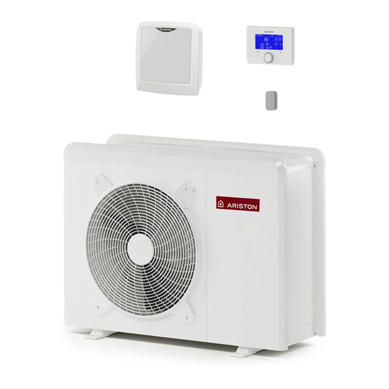
DESCRIZIONE DEL SISTEMA Composizione del sistema Il sistema NIMBUS POCKET M NET composto da: - Un’unità interna - Un’unità esterna - Un dispositivo di controllo remoto - Una sonda di temperatura esterna - Una Sensys Net per la connettività Per ulteriori informazioni sugli accessori disponibili, si pre- ga di consultare il Catalogo Prodotti. - Page 8 70 - 70 M-T EXT 1016 ø 10 90 110 M-T EXT 1016 ø 10 8 / IT...
-
Page 9: Pressione Disponibile
UNITA INTERNA Dimensioni e pesi (mm) 314 mm Peso Limiti di funzionamento in raff rescamento Limiti di funzionamento in riscaldamento -10,60 35,60 (43 ; 23) (10 ; 23) -20,45 35,33 -20,20 15,20 (10 ; 5) (43 ; 5) A - Temperatura acqua in uscita (°C) esempio 1: B = 35 e A = 33 B - Temperatura esterna dell’aria (°C) PRESSIONE DISPONIBILE... - Page 10 TAGLIA MODELLI Soglia di OFF fl ussimetro [l/h] Soglia di ON fl ussimetro [l/h] Flusso nominale [l/h] 40 M 50 M 70 M 1120 70 M-T 1120 90 M-T 1440 110 M-T 1755 Pressione disponibile Le curve indicate tengono conto delle perdite di carico attribuibili all’unità interna. In questo modo è...
-
Page 11: Dispositivo Di Controllo Remoto
Aggiungendo una Sonda Esterna Ariston: Classe del controllo di temperatura Contributo all'effi cienza energetica % per il riscaldamento degli ambienti In un sistema a 3 zone con 2 Sensori ambiente Ariston: Classe del controllo di temperatura VIII Contributo all'effi cienza energetica % per il riscaldamento degli ambienti... -
Page 12: Guida All'installazione
Scelta del posizionamento GUIDA ALL’INSTALLAZIONE • Evitare il posizionamento dell’unità esterna in luoghi di diffi cile accesso per le successive operazioni di installazione e manu- tenzione. Attenzione • Evitare il posizionamento in prossimità di fonti di calore. L’installazione dell’unità esterna ed interna deve sempre es- •... -
Page 13: Procedura Di Apertura Dei Passaggi Per I Collegamenti
2. Rimozione pannello frontale Attenzione Rimuovere le viti che bloccano il pannello frontale, tirarlo Prima dell’installazione verifi care la resistenza e in avanti e verso il basso. l’orizzontalità della base di appoggio. Basandosi sulle immagini sotto riportate, fi ssare solidamente la base dell’unità... -
Page 14: Unità Interna
UNITÀ INTERNA (Fig. 1) Installazione preliminare L’apparecchio è progettato per l’installazione a parete. Assicurarsi dopo il trasporto che tutti i componenti siano intatti e non siano stati danneggiati dagli urti. In caso di danni evidenti al prodotto, non procedere all’ins- tallazione, ma rivolgersi ad un centro autorizzato. - Page 15 INSTALLAZIONE FINALE DELL’INTERO SISTEMA ATTENZIONE I collegamenti elettrici devono essere realizzati dopo aver completato tutti i collegamenti idraulici. Il circolatore dell’unità esterna spinge l’acqua verso il sistema di riscaldamento/raff rescamento. L’apparecchio è composto da una scatola in cui sono contenute le morsettiere per le connessioni elettriche di bassa tensione, alta tensione e alimentazione.
-
Page 16: Collegamenti Elettrici
COLLEGAMENTI ELETTRICI Attenzione I collegamenti elettrici vanno eff ettuati dopo aver completato tutti i collegamenti idraulici. L’ unità interna e l’unità esterna devono essere alimentate separatamente seguendo quanto indicato sulle tabelle della norma NF C 15-100. Tra l’unità interna ed esterna dovrà inoltre essere eff ettuata una connessione di tipo MOD BUS. Questa connessione potrà... -
Page 17: Connessioni Elettriche Dell'unità Esterna
ATTENZIONE: Eseguire il collegamento a terra prima di tutti gli altri collegamenti elettrici. Le unità interne ed esterne devono essere alimentate separatamente. Per evitare qualsiasi rischio, il cavo di alimentazione dell’unità esterna ed interna deve essere sostituito solo da tec- nici specializzati . -
Page 18: Connessioni Elettriche Dell'unità Interna
Connessioni elettriche dell’unità interna Prima di ogni intervento sul sistema, interrompere l’alimenta- zione dall’interruttore generale. Rispettare le connessioni di neutro e fase. Per accedere al quadro elettrico dell’unità interna, rimuovere le tre viti indicate in fi gura (A) ed estrarre il coperchio del quadro elettrico (B). -
Page 19: Connessioni Elettriche Tra Unità Interna Ed Unità Esterna
Connessioni elettriche tra unità interna ed unità esterna Prima di ogni intervento sul sistema, interrompere l’alimentazione dall’interruttore generale. 1 ph 3 ph 30mA 30mA EH1 EH1 ST1 ST1 ANODE TA 1 TA 2 TNK BUF +24V AUX 1 NOTA Si raccomanda di verifi care la presenza di dispositivi di protezione da sovralimentazioni (SPD) nella linea MT e la presenza di interruttori di sicurezza diff erenziali e di interruttori magnetotermici in uscita al quadro elettrico che ali- menta l’unità... -
Page 20: Schema Elettrico - Quadro Unità Esterna
SCHEMA ELETTRICO - QUADRO UNITÀ ESTERNA 1 ph 3 ph 20 / IT... -
Page 21: Schema Elettrico - Quadro Unità Interna
SCHEMA ELETTRICO - QUADRO UNITÀ INTERNA (WH 90 110 S) BK = Nero YE = Giallo BN = Marrone GN = Verde BU = Blu GY = Grigio RD = Rosso WH = Bianco OR = Arancio PI = Rosa ENERGY MANAGER YE/GN CN14... -
Page 22: Installazione Dell'interfaccia Di Sistema
INSTALLAZIONE DELL’INTERFACCIA DI SISTEMA Posizionamento L’interfaccia di sistema riconosce la temperatura ambiente, per cui si deve tener conto di questo fattore nello sce- gliere il posizionamento della stessa. Si consiglia un posizionamento lontano da fonti di calore (radiatori, esposizione diretta alla luce solare, camini etc.) così... - Page 23 Interfaccia di sistema simboli display: Tasti e display: 1. tasto indietro « «(visualizzazione precedente) Estate / Impostazioni acqua calda 2. manopola ) Inverno 3. tasto «OK» Solo riscaldamento (conferma l’operazione o accede al menu principale) 4. DISPLAY Raff rescamento OFF sistema spento Programmazione oraria Funzionamento manuale Temperatura ambiente desiderata...
-
Page 24: Procedura Di Accensione
Premere il tasto OK. Ruotare la manopola e selezionare: ATTENZIONE Per garantire la sicurezza e il corretto funzionamento 17.0 PARAMETRI UTENTE dell’interfaccia di sistema, la messa in funzione deve 17.0.0 Impostazione Riscaldamento essere eseguita da un tecnico qualifi cato in possesso Premere il tasto OK. - Page 25 voltaico. grazione. 17.1.3 Ingresso AUX 1 17.2.8 Tipo di unità esterna - Nessuna funzione - SPLIT - Ingresso umidostato: quando il contatto è chiuso la pom- - MONO pa di calore è spenta durante il ciclo raff rescamento. 17.2.9 Abilitazione antibloccaggio circolatore 17.1.4 Uscita AUX 1 (AFR) Attiva la funzione di antibloccaggio del circolatore prima-...
- Page 26 17.79 Attivazione riscaldatori elettrici unità esterna NOTA: L’accumulo di acqua sanitaria viene riscaldato - OFF solo dalla pompa di calore quando l’ingresso EDF è abi- - ON (attiva la resistenza elettrica posta nel pannello litato (vedi par. 17.1.0) e commuta alla tensione di 230V dell’unità...
- Page 27 Premere il tasto OK. 17.8.6 Confi gurazione potenza resistenze elettriche Dopo aver verifi cato la disponibilità del servizio Ariston Imposta la confi gurazione della resistenza elettrica di ba- Net nel proprio paese seguire le istruzioni riportate nel KIT ckup SENSYS NET.
-
Page 28: Termoregolazione
TERMOREGOLAZIONE La verifi ca dell’idoneità della curva scelta richiede un tem- Per impostare i parametri di termoregolazione premere po lungo nel quale potrebbero essere necessari alcuni contemporaneamente i tasti indietro “ “ e “OK” fi no alla aggiustamenti. Al diminuire della temperatura esterna (in- visualizzazione sul display “Inserimento codice “. - Page 29 TERMOREGOLAZIONE RAFFRESCAMENTO All’aumentare della temperatura esterna (estate) si posso- Per impostare i parametri di raff rescamento premere con- no verifi care tre condizioni: temporaneamente i tasti indietro “ “ e “OK” fi no alla 1. la temperatura ambiente aumenta, questo indica che bi- visualizzazione sul display “Inserimento codice “.
- Page 30 IMPOSTAZIONE DESCRIZIONE RANGE DI FABBRICA RETE Rete BUS Interfaccia di sistema Energy Manager Rete BUS attuale Pompa di calore Sensore ambiente Controllo multi zona Interfaccia di sistema Nessuna zona selezionata Numero zona Zona selezionata Correzione temperatura ambiente - 3; +3 Versione SW interfaccia PARAMETRI ZONA 1 Impostazione Temperature...
- Page 31 IMPOSTAZIONE DESCRIZIONE RANGE DI FABBRICA Velocità fi ssa Modulazione pompa zona Modulante su deltaT Modulante su deltaT Modulante su pressione DeltaT obbiettivo per modulazione 4 ÷ 25°C 7°C (LT) - 20°C (HT) Velocità fi ssa pompa 20 ÷ 100% 100% Raff rescamento T Set Z1 Raff rescamento par.
- Page 32 IMPOSTAZIONE DESCRIZIONE RANGE DI FABBRICA Temperatura mandata sola lettura Temperatura ritorno sola lettura Stato Richiesta Calore Z2 OFF - ON sola lettura Stato Pompa OFF - ON sola lettura Dispositivi Zona 2 Velocità fi ssa Modulazione pompa zona Modulante su delta T Modulante su delta T Modulante su pressione DeltaT obbiettivo per modulazione...
- Page 33 IMPOSTAZIONE DESCRIZIONE RANGE DI FABBRICA Ultimi 10 errori 2 Reset Lista Errori 2 Resettare? OK=Sì, esc=No Reset Menu Ripristino Impost di Fabbrica Resettare? OK=Sì, esc=No Ripristino Impost di Fabbrica 2 Resettare? OK=Sì, esc=No PARAMETRI SISTEMA POMPA DI CALORE Parametri utente Modalità...
- Page 34 IMPOSTAZIONE DESCRIZIONE RANGE DI FABBRICA Comp Temp mandata PC 0 ÷ 10°C 2°C Tempo Incremento Temp Risc 0 ÷ 60 min. 16 min. Correzione T esterna -3 ÷ +3°C 0°C 1 stadio Stadi di attivazione resistenza 2 stadi 2 stadi 3 stadi Presenza anodo Pro-Tech OFF - ON...
- Page 35 IMPOSTAZIONE DESCRIZIONE RANGE DI FABBRICA Resistenza elettrica 2 OFF - ON Resistenza elettrica 3 OFF - ON Anodo Pro-Tech OFF - ON Modo manuale - 2 Attivazione modalità manuale OFF - ON Forza la pompa in riscaldamento OFF - ON Forza la pompa in raff reddamento OFF - ON Modalità...
- Page 36 IMPOSTAZIONE DESCRIZIONE RANGE DI FABBRICA Temp mandata acqua pompa calore sola lettura Temp ritorno acqua pompa calore sola lettura Temp evaporatore sola lettura Temp aspirazione compr. sola lettura Temp mandata compr. sola lettura Temp del refrigerante sola lettura sola lettura Diagnostica Pompa Calore - 2 Stand by Raff rescamento...
- Page 37 IMPOSTAZIONE DESCRIZIONE RANGE DI FABBRICA Stato resitenza nel bacino sola lettura Corrente compressore sola lettura Diagnostica scheda -1 Ingressi stand-by antigelo riscaldamento sanitario funzione sanifi cazione termica funzione disareazione funzione chimney Ciclo asciugatura del massetto no generazione calore Stato sistema sola lettura modo manuale errore...
- Page 38 IMPOSTAZIONE DESCRIZIONE RANGE DI FABBRICA Reset Menu Ripristino Impost di Fabbrica Resettare? OK=Sì, esc=No Confi gurazione connettività ON/OFF della rete Wi-Fi Confi gurazione rete Confi gurazione WPS Orario Internet Info Connettività Inizializzazione Idle Inizializzazione Acess Point Modalità Acess Point Stato connettività Connessione WiFI in corso WiFi connessa Connessione cloud in corso...
-
Page 39: Manutenzione
• Riportare in pressione il sistema, disareandolo quando MANUTENZIONE necessario • Regolare i parametri di settaggio e i dispositivi di regola- ATTENZIONE zione al fi ne dell’ottenimento di un miglior funzionamen- Per garantire la sicurezza e il corretto funzionamento la ma- to e di una gestione più... -
Page 40: Lista Errori Unità Interna
LISTA ERRORI UNITÀ INTERNA ERRORE DESCRIZIONE RISOLUZIONE - Attivazione della termoregolazione basata sulla sonda esterna. Sonda Esterna Difettosa - Sonda esterna non connessa o danneggiata. Sovraccarico alimentazione bus Sonda Mandata Z1 Difettosa Sonda Mandata Z2 Difettosa Sonda Mandata Z3 Difettosa Sonda Ritorno Z1 Difettosa Sonda Ritorno Z2 Difettosa Sonda Ritorno Z3 Difettosa... - Page 41 - Controllare l’attivazione del circolatore principale - Controllare il fl usso con il valore fl ussimetro tramite il parametro Secondo termostato resistenza (manuale) 17.11.3 - Controllare lo stato del termostato di sicurezza e cablaggi - Controllare l’attivazione del circolatore principale - Controllare il fl...
-
Page 42: Lista Errori Unità Esterna
LISTA ERRORI UNITÀ ESTERNA RESET ERRORE DESCRIZIONE 1ph 3ph INVERTER ERRORE SER- DESCRIZIONE POWER VICE Sovratemperatura Dissipatore RESET Sovracorrente IPM Compressore Errore pilotaggio compressore Start-up Compressore Fallito Errore pilotaggio ventilatore Sovracorrente Compressore Errore pilotaggio valvola 4 vie Mancanza di fase AC Ingresso Errore pilotaggio valvola espan- Errore Misura Corrente IPM Compressore sione... - Page 43 Targa Dati dell’Unità Interna Targa Dati dell’Unità Esterna Legenda: 1 Marchio Legenda: 2 Modello 3 Dati riscaldamento 1. Marchio 4 Prestazione nominale riscaldamento 2. Produttore 5 Dati raff rescamento 3. Modello - Nr. di serie 6 Prestazione nominale raff rescamento 4.
- Page 44 INDEX Overview Electrical wiring Safety regulations .................. 46 Electrical circuit ..................60 Characteristics of the water supplied to the appliance ..... 48 Table of electrical connections ............60 External Unit electrical connection ............ 61 System description Internal Unit electrical connection ............ 62 System compositions ................
- Page 45 Perform all electrical connections using wi- SAFETY REGULATIONS res which have a suitable section.he electri- CAUTION cal connection of the product must be done This manual constitutes an integral and following the instruction manual in the relati- essential part of the product. It must be kept ve paragraph.
- Page 46 Make sure any portable ladders are positio- Personal injury caused by electrocution, fal- ned securely, that they are suitably strong ling splinters or fragments, inhalation of dust, and that the steps are intact and not slippery shocks, cuts, puncture wounds, abrasions, and do not wobble when someone climbs noise and vibration.
- Page 47 Don’t step upon the external and internal unit. This product conforms Personal injury or damages to the ap- to Directive WEEE 2012/19/EU. pliance. The symbol of the crossed waste paper basket on the Never leave the external unit open, without appliance indicates that at the end of its working life the its housing, for longer than strictly neces- product should be disposed of separately from normal...
- Page 48 SYSTEM DESCRIPTION System composition NIMBUS POCKET M NET System consists of: - External unit - Internal unit - System interface - Outdoor sensor - Sensys Net for connectivity For more information on available accessories, please refer to the product catalogue. EXTERNAL UNIT As external unit, one of the following models is provided: •...
- Page 49 70 M - 70 M-T EXT 1016 ø 10 90 -110 M-T EXT 1016 ø 10 49 / GB...
- Page 50 INTERNAL UNIT Weights and dimensions (mm) 314 mm Weight Restrictions of cooling operation Restrictions of heating operation -10,60 35,60 (43 ; 23) (10 ; 23) -20,45 35,33 -20,20 15,20 (10 ; 5) (43 ; 5) A - Flow water temperature (°C) Example: 1B = 35 and A = 33 B - External air temperature (°C) AVAILABLE PRESSURE...
- Page 51 Flowmeter OFF Flowmeter ON System Size Nominal fl ow rate [l/h] Threshold [l/h] Threshold [l/h] 40 M EXT 50 M EXT 70 M EXT 1120 70 M-T EXT 1120 90 M-T EXT 1440 110 M-T EXT 1755 Available pressure The curves indicated above show the available pressure of internal units. In order to have a correct sizing of the system, the pressure drop curve of the entire circuit (in function of the nominal fl ow rate) must stay below the available pressure curve everywhere.
- Page 52 Adding an ARISTON OUTDOOR SENSOR: Class of the temperature control Contribution to seasonal space heating energy effi ciency in % In a 3-zones system with 2 ARISTON ROOM SENSORS Class of the temperature control VIII Contribution to seasonal space heating energy effi ciency in %...
- Page 53 Choice of placement INSTALLATION GUIDE • Avoid a mounting where the ODU is surrounded by walls • Avoid a mounting in sinks. Cold air sinks down and by that Warning air short circuit could occur. The appliance must be installed by a qualifi ed technician in •...
- Page 54 2. Removal of frontal panel Attention Remove the screws that block the frontal panel and pull it Before installation, check strength and horizontality of forward and down. the base. Based on the pictures, connect the base of the external unit fi rmly to the ground, using suitable anchor bolts (M10 x 2 pairs).
- Page 55 INTERNAL UNIT (Fig. 2) Preinstallation NIMBUS POCKET M NET is designed for wall installation. Make sure that all module components are intact following trans- port and handling and have not been damaged by knocks. In case of evident damages to the product, do not proceed with installation.
- Page 56 FINAL INSTALLATION OF THE WHOLE SYSTEM Attention The electrical connections are made after completing all hydraulic connections The circulation pump which drives the fl uid between the external unit and the heating/cooling system in positioned in the exter- nal unit. The Light box is consisted in one box in which are contained the electrical blocks: low voltage, high voltage and power supply.
- Page 57 ELECTRICAL WIRING ATTENTION The electrical connections shall be made after completing all hydraulic connections. The internal and external units must be powered separately according to what is indicated on the tables. Between the internal and external units should also be made a MOD BUS connection. This connection may be made through the use of a cable of reduced section (recommended section 0,75 mm ).
- Page 58 WARNING: Make ground connection prior to any other electrical connections. The internal and external units must be powered separately. To prevent any risk, the power supply cable of the outdoor and indoor unit must only be replaced by the technicians of the after-sales service.
- Page 59 Internal Unit electrical connection Before any operation on the system, turn off the main power. Observe the phase and neutral connections. To access the control panel of the internal unit, proceed as follows: Re- move the three screws (A) indicated in fi gure and remove the cover of the electrical panel (B).
- Page 60 Electrical connections between internal and external unit Before any work on the system, shut off the power at the breaker. 1 ph 3 ph 30mA 30mA EH1 EH1 ST1 ST1 ANODE TA 1 TA 2 TNK BUF +24V AUX 1 NOTE It is strongly recommended to verify the presence of a surge protection device (SPD) on main power line and of circuit breakers connected to the external and internal unit’s control box...
- Page 61 ELECTRICAL SCHEME - BOX OF EXTERNAL UNIT 1 ph 3 ph 61 / GB...
- Page 62 ELECTRICAL SCHEME - LIGHT BOX 1Z BK = Black BN = Brown Green BU = Blue GY = Grey RD = Red WH = White OR - Orange PI - Pink YE = Yellow ENERGY MANAGER YE/GN CN14 YE/GN YE/GN PM AUX ANODE TA 1...
- Page 63 INSTALLATION OF SYSTEM INTERFACE Positioning The system interface recognizes the temperature of the environ- ment, so this factor must be taken in consideration during the choice of the positioning of the same. We recommend to place the remote control away from sources of heat (radiators, direct exposure to sunlight, fi...
- Page 64 Display symbols: Buttons and Display: 1. back button (previous screen) Summer / DHW settings 2. knob ) Winter button Only Winter / CH settings (to confi rm operation or access main menu) Cooling 4. DISPLAY OFF, system off ) Time program ) Manual operation Desired room temperature Room temperature detected...
- Page 65 Press the OK button to confi rm. WARNING Turn the knob and select: To guarantee safety and correct operation of the system - ON (active function to reduce noise) interface, it must be commissioned by a qualifi ed techni- - OFF cian in possession of the skills as required by law.
- Page 66 - 0: Fixed Low Speed 17.1.5 AUX Output 2 (Come AUX1 OUT1) - 1: Fixed High Speed 17.1.6 AUX P2 Circulator Setting - 0: Auxiliary circulator: circulator follows in parallel the - 2: Modulating speed control switch on/off of the primary circulator P1 17.3.4 EM Delta T Pump Setpoint - 1: Cooling circulator: driven ON when Cooling mode se-...
- Page 67 17.5.5 Thermal Cleanse Function start time Defi ne the start time of the thermal cleanse function 17.5.6 Thermal Cleanse Function frequency Set the period after wich a new Thermal Cleanse is per- formd Push OK button. Turn the knob and select: 17.6 MANUAL MODE - 1 Manual activation of the system components (circulators,...
- Page 68 17.8.5 Refrigerante Recover Cycle Activate this function to recover the refrigerant gas before every maintenance operation on the refrigerant circuit. 17.8.6 Resistance Power Rating Confi guration set the backup resistance confi guration - 0: if the backup interface module comprizes 2kW+2kW (+2kW) electrical resistances - 1: if the backup interface module comprizes 2kW+4kW electrical resistances...
- Page 69 THERMOREGULATION The checking process for the suitability of the curve re- To set the temperature adjustment parameters, simultane- quires a long period of time during which several adjust- ously press and hold the back “ “ and “OK” buttons until ments may be necessary.
- Page 70 To set the temperature adjustment parameters, simultaneously When the outdoor temperature rises (summer), three condi- press and hold back “ “ and “OK” buttons until “Enter code” tions may arise: appears on the display. Turn the knob to enter the technical 1.
- Page 71 DESCRIPTION RANGE DEFAULT NETWORK BUS network System interface Energy Manager Network presence Heat Pump Room Sensor Zone Manager System interface No zone selected Zone number Zone selected Room temperature correction - 3; +3 SW Version Interface ZONE1 PARAMETERS Setpoint T Day 10 - 30 °C 19°C Heat - 24°C Cool T Night...
- Page 72 DESCRIPTION RANGE DEFAULT Off set [-2,5°C; +2,5°C] MinT -12°C [FC]; 12°C [FC]; Max T MinT - 23°C [UFH] 23°C [UFH] 7°C [FC]; Min T 7°C-MaxT [FC]; 18-MaxT [UFH] 18°C [UFH Target deltaT for pump modulation cooling [-5; -20°C] -5°C Zone 2 Parameters (if present) Setpoint T Day 10 - 30 °C...
- Page 73 DESCRIPTION RANGE DEFAULT ON/OFF Thermoregulation type Fix Flow T ON/OFF Outdoor T Only Slope [18;33] FC; [0-30] UFH 25 FC; 10 UFH Off set [-2,5°C; +2,5°C] 0°C MinT -12°C [FC]; 12°C [FC]; Max T MinT - 23°C [UFH] 23°C [UFH] 7°C [FC];...
- Page 74 DESCRIPTION RANGE DEFAULT Not Defi ned Absent HV Input 1 Absent External switch off signal Not Defi ned Absent HV Input 2 Absent DLSG Not active HV Input 3 Not active PV Integration Active None AUX Input 1 None Humidistat sensor None Fault alarm AUX Output 1 (AFR)
- Page 75 DESCRIPTION RANGE DEFAULT Cooling Cooling not active Cooling mode activation Cooling not active Cooling active Cooling anticycling time 0 -10 min. 0 min. DeltaT_HP_Flow_Comp -10 ÷ 0°C -2°C Domestic Hot Water DHW Comfort Setpoint T 35 ÷ 65°C 55°C DHW Reduced Set Point T 35°C - Par.
- Page 76 DESCRIPTION RANGE DEFAULT Functional Heating Curing Heating Floor drying cycle Functional Heating + Curing Heating Curing Heating + Functional Heating Manual Floor drying total Remaining Days only read Floor drying functional Remaining Days only read Floor drying curing Remaining Days only read Refrigerant Recover OFF - ON...
- Page 77 DESCRIPTION RANGE DEFAULT Last inverter error only read HP Diagnostics - 3 Inverter Capacity 0 ÷ 15 kW only read (kW) HP Actual Compressor frequency 0 ÷ 1100 Hz only read (Hz) HP Set Compressor Modulation 0 ÷ 100% only read (%) Electric Heater 1 only read Main circulator status...
- Page 78 DESCRIPTION RANGE DEFAULT Error History Last 10 Errors only read Reset Error List Reset? OK=Yes,esc=No Reset Menu Reset Factory Settings Reset? OK=Yes,esc=No Service reset Reset? OK=Yes,esc=No compressor timer reset Reset? OK=Yes,esc=No Connectivity Connectivity Settings ON/OFF Wi-Fi Network Network confi guration WPS Confi...
- Page 79 Antifreeze function of the external unit MAINTENANCE The main circulator of the internal unit starts at the minimum speed when the measured temperature by the return Maintenance is an essential operation to insure safety, cor- rect working and duration of life of the appliance. water temperature (EWT) sensor is below 7°C in heating It must be carried out in accordance with the regulations in mode or the leaving water temperature (LWT) sensor is...
- Page 80 INTERNAL UNIT ERROR LIST ERROR DESCRIPTION TROUBLESHOOTING Activation of thermoregulation based on outdoor sensor and outdo- Outdoor Sensor Damaged or sensor not connected or damaged Bus supply overload Zone1 Send Probe Damaged Zone2 Send Probe Damaged Zone3 Send Probe Damaged (N/A) Zone1 Return Probe Damaged Zone2 Return Probe Damaged Zone3 Return Probe Damaged (N/A)
- Page 81 - Check main circulation activation First thermostat of resistance (auto) - Check water fl ow by par 17.11.3 - Check safety thermostat status and wirings Check main circulation activation Second thermostat of resistance (manual) - Check water fl ow by par 17.11.3 - Check safety thermostat status and wirings Night tariff contact not present - Par 17.5.2 = HP-HC or HP-HC 40°C and par.
- Page 82 EXTERNAL UNIT ERROR LIST INVERT- RESET DESCRIPTION 1ph 3ph DESCRIPTION HP POWER SERVICE ERROR ERROR RESET Heat Sink-Overheat HP FAN Mismatch Error Compressor Ipm Over-Current HP V4W Mismatch Error Compressor Fail To Drive HP EXV Mismatch Error Compressor Over-Current HP Zero Fan Speed Input Voltage Lack Of Phase HP Comunication error Compressor Ipm Current Sampling Failure...
- Page 83 Internal unit data plate External unit data plate Legend: Legend: 1. Homologation Brand 2. Certifi cation Manufacturer 3. Model Appliance model - Serial number 4 Performance Ratings heating circuit Commercial reference 5 Cooling date Certifi cation number 6 Performance Ratings cooling circuit Electrical data 7 Type of oil in the refrigerant circuit 11.
- Page 84 Ariston Thermo SpA Viale Aristide Merloni, 45 60044 Fabriano (AN) Italy Telefono 0732 6011 Fax 0732 602331 info.it@aristonthermo.com...
Need help?
Do you have a question about the NIMBUS POCKET 40 M EXT NET and is the answer not in the manual?
Questions and answers