
Subscribe to Our Youtube Channel
Related Manuals for Ariston NIMBUS POCKET M NET R32 Series


Summary of Contents for Ariston NIMBUS POCKET M NET R32 Series
- Page 1 NIMBUS POCKET M NET R32 3301725 TECHNICAL INSTRUCTIONS FOR INSTALLATION AND MAINTENANCE 420000656400...
- Page 2 The ARISTON product is covered by a conventional warranty, The user must therefore deliver the decommissioned product which takes effect from the date of purchase of the appliance.
-
Page 3: Table Of Contents
Contents 1. Safety advices 6. Commissioning 1.1 General warnings and safety instructions 6.1 Checking for electrical dispersions and gas leakages 1.2 Use of the R32 refrigerant 6.1.1 Electrical safety checks 1.3 Symbols affixed to the appliance 6.1.2 Check for gas leakages 2. -
Page 4: Safety Advices
General warnings and safety instructions and/or not authorised by the manufacturer. This manual is the property of ARISTON and it It is also forbidden to make changes to is forbidden to reproduce or transfer to third the product’s software programme for the... - Page 5 Safety advices When connecting the cooling system, avoid During all work procedures, wear individual substances or gases other than the speci- protective clothing and equipment. Do not fied refrigerant from entering the unit. The touch the installed product if barefoot and/ presence of other gases or substances in the or with any wet part of the body.
-
Page 6: Use Of The R32 Refrigerant
Safety advices Use of the R32 refrigerant FLAMMABLE MATERIAL The R32 refrigerant is odourless. This system contains fluorinated refrigerant. For specific information on the type and quantity of refrigerant, refer to the data plate. Always observe the national regulations on the use of refrigerant. -
Page 7: Symbols Affixed To The Appliance
Safety advices Symbols affixed to the appliance The appliance has the following symbols affixed to it: Outdoor unit (ODU) Fig. 1 Reference Description Danger moving parts Danger flammable refrigerant Normative symbols for R32 gas Serial number 000000000000 Electrical precautions 7 / EN... -
Page 8: Description Of The System
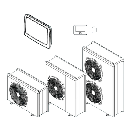
Description of the system 2. Description of the system Outdoor unit (ODU) 2.1.1 Structure The outdoor unit supplied is one of the following models: – NIMBUS 35 M EXT R32 – NIMBUS 50 M EXT R32 – NIMBUS 80 M EXT R32 –... -
Page 9: Dimensions And Weights
Description of the system 2.1.2 Dimensions and weights 120 M & M-T 150 M & M-T Outdoor unit (ODU) Weight [kg] 1016 mm 374 mm NIMBUS EXT R32 35 M - 50 M NIMBUS EXT R32 80 M NIMBUS EXT R32 80 M-T NIMBUS EXT R32 120 M - 150 M NIMBUS EXT R32 120 M-T - 150 M-T 35 M - 50 M... -
Page 10: Hydraulic And Drainage Fittings
Description of the system 2.1.3 Hydraulic and drainage fittings Indoor unit (IDU) The NIMBUS LB M R32 indoor unit comprises a module that 89 mm contains the terminal boards for the electrical connections and 71 mm the Energy Manager 2.2.1 Dimensions and weights G 1”F G 1”F... -
Page 11: Operational Limits
Description of the system Operational limits 2.3.1 Compressor frequency table The maximum allowed frequency varies with the outdoor tem- The following diagrams show the limits of the heat pump. The perature. temperature difference between the delivery and return of the The values shown in the table refer to the following conditions: plate heat exchanger must be between 5°C and 8°C. -
Page 12: System Interface Sensys Hd
Operation icons °C 1,5 bar M Pressure indication The SENSYS HD interface is compatible with Aris- ton NET when used with an ARISTON Wi-Fi mod- ule. Find out more on www.Ariston.com Fig. 12 SYMBOLS SYMBOLS Wi-Fi module update in progress... -
Page 13: Technical Data
– Connect the wire to the terminal (C) by introducing it space heating from the lower part after creating a suitable passage. In a system with 3 zones with 2 ARISTON room Sen- – Place the sensor cover back in the correct position. sors:... -
Page 14: Installation
Installation 3. Installation – Ensure that all applicable national safety standards are observed throughout the course of the installation. – Ensure that the system is adequately earthed. Preliminary warnings – Ensure that the power supply voltage and frequency match those required by the outdoor unit, and that the The appliance must be installed exclusively by installed power is sufficient for its operation. -
Page 15: Receiving The Product
Installation Receiving the product Upon receiving the product, make sure that its contents are intact and complete and, if they do The NIMBUS POCKET M NET R32 system is supplied in multiple not match the order, contact the branch that sold items protected by a cardboard pack: the appliance. -
Page 16: Noise Level
Installation Minimum installation distances 3.3.2 Noise level To limit noise pollution and the transmission of vibrations is it possible to: – Install the outdoor unit on a metal frame or on a vibra- tion-damping base. Vibration dampers must be mount- ed to reduce the transmission of vibrations. -
Page 17: Installation
Installation 3.3.4 Installation The outdoor unit must be anchored to the floor or to a wall-mounted bracket. Before installing the system, check that its sup- porting base is sufficiently resistant and the sur- face is leveled. Arrange the unit’s installation base according to the dimen- sions shown below. -
Page 18: Arranging The Connections
Installation 3.3.5 Arranging the connections 3.3.6 Installing the accessory kit Anti-freeze kit (A) – To allow the passage of cables, use a appropriate tool to remove the pre-cut pieces (1) from the unit’s frame. – To detach the pre-cut pieces effectively, keep the unit’s front panel fitted on. -
Page 19: Installing The Indoor Unit
Installation Installing the indoor unit – To ensure correct operation of the kit, the unit must rest on a base measuring at least 70 mm. 3.4.1 Place of installation The indoor unit is designed for wall mounting. Make sure that all the module’s components are intact after transport and handling, and that they have not been damaged by impacts. -
Page 20: Hydraulic Connections
Hydraulic connections 4. Hydraulic connections 4.4.4 Available pressure Make sure that the available pressure is not lower than the head loss of the entire hydraulic system. 4.4.1 Minimum water content The curves in the pictures below shown the available pressure on the flow from the outdoor unit. -
Page 21: Characteristics Of The Supply Water
Hydraulic connections 4.4.5 Characteristics of the supply water The accumulation of air can cause malfunctions to the system and damage the components. Make sure that the system is supplied with water having a hard- ness between 8°F and 15°F and conductivity below 500 μS/cm. If frequent fillings (once a month or more fre- In zones where the water is particularly hard, mount a water quently) are required for your system, this indi-... -
Page 22: Example Of Schematic Hydraulic Diagram
Hydraulic connections Example of schematic hydraulic diagram Fig. 32 Lightbox EH1 EH1 ST1 ST1 L EH1 EH1 ST1 ST1 L1 L2 L3 EBUS PM AUX ANODE IN AUX2 POWER AUX1 AUX2 AUX1 AUX4 AUX3 G +24V GND Fancoil: Z0 Underfloor Heating: Z1 ANODE +24V CHILLER BOILER... - Page 23 Hydraulic connections Symbol Description Symbol Description Symbol Description System flow Hydraulic circuit-breaker CUBE System return Buffer Timer-controlled thermo- Communication connec- stat tion Lightbox Electrical connection Storage active Domestic cold water inlet Zone manager Domestic hot water outlet Refrigerant circuit 2-zone wired control DHW expansion vessel Gas supply module...
- Page 24 Hydraulic connections NOTE: Installation of a tank for the production of Do- mestic Hot Water When a tank is installed to produce domestic hot water, the installer must verify and provide evidence of conformity with respect to the following regulations: –...
-
Page 25: Electrical Connections
Electrical connections 5. Electrical connections – Check that the electrical installation is adequate for sup- porting the power consumption of the installed units, as indicated on the appliances’ data plate. Carry out the electrical connections after having – The electrical connections must be made with the help completed all the hydraulic connections. - Page 26 Electrical connections The cross-sectional size of the cables used must comply with the system power (see data plate). The cross-sectional size of the power cables indicated in the table must be regarded as the minimum cross-sectional -size. Prior to accessing the terminals, all the supply circuits must be disconnected. OUTDOOR UNIT NIMBUS EXT R32 35 M...
-
Page 27: Outdoor Unit Electrical Connections
Electrical connections Outdoor unit electrical connections 1-ph outdoor unit terminal board In accordance with the installation instructions, all systems for disconnecting the main power supply must have an open contact (4 mm) that guarantees full disconnection as per the indications of the Class III overvoltage conditions. Make the earth connection before proceeding ⏚... - Page 28 Electrical connections The ST1 connection is bridged by default. Do not remove the jumper. If the installation involves the use of thermo- stats or timer-controlled thermostats to manage the heat request, it is necessary to ensure that they do not have a proportional-band control logic.
-
Page 29: Indoor Unit Electrical Connections
Electrical connections Indoor unit electrical connections Power supply connections Before carrying out any work on the system, shut off the power supply at the main switch. Comply with the neutral and phase connections. ... - Page 30 Electrical connections The cross-section and length of the cables must be sized ac- Reference Description cording to the power indicated on the indoor unit’s data plate. ANODE Connection to the tank protection anode. Once you have completed the connections be- Observe the electrical polarities.
-
Page 31: Example Of Electrical Connection Between Indoor And Outdoor Units
Electrical connections Example of electrical connection between indoor and outdoor units Before carrying out any work on the system, shut off the power supply at the main switch. The electrical connection between the indoor and outdoor units must be made using the two low-voltage terminal boards: G and Connect “G”... -
Page 32: Installing The System Interface
Electrical connections Installing the system interface – Position the system interface on the base, pushing it slightly downwards. Note: when installing cascade systems, to install the system interface refer to the relevant dedicated manual. Positioning The system interface detects the room temperature. This factor must be taken into account when choosing its position. -
Page 33: Commissioning
Commissioning 6. Commissioning Preliminary checks OUTDOOR UNIT – The unit must be positioned on a sturdy and perfectly Checking for electrical dispersions and gas horizontal base, in a place that is easily accessible for leakages subsequent maintenance operations. – If there are significant air draughts, a protective screen 6.1.1 Electrical safety checks must be fitted and positioned at an appropriate dis-... -
Page 34: Initial Start-Up
Commissioning HYDRAULIC CONNECTIONS Initial start-up – The water supply distribution network pressure must To guarantee safety and correct operation of the never exceed 0.5 MPa (5 bar), otherwise a pressure re- system interface, it must be commissioned by a ducer must be installed on the system’s intake. qualified and competent technician in posses- –... -
Page 35: Basic Functions
Commissioning Basic functions Room temperature adjustment with AUTO function on If the heating hot water temperature does not match the de- The system interface is a device that controls the heating sys- sired value, it can be increased or decreased via the “Heating tem. -
Page 36: Technical Parameters
Commissioning Technical parameters 1.0.6 Thermoregulation Press the selector . Turn the selector to choose the de- Simultaneously press the “Esc” and “Menu” buttons until “Insert sired item. Code” appears on the display. Provisioned - Not active. Turn the selector to enter the technical code (234) then press Active. - Page 37 Commissioning 1.1.1 HV input 2 (input configurable to 230 V) Heat / Cool by external control: when the contact is closed, the operating mode is set to cooling; when the contact is Press the selector . Turn the selector to choose the de- opened, the operating mode is set to heating.
- Page 38 Commissioning 1.1.8 System flow T selection Safety thermostat: connect an underfloor safety thermo- stat to the contact. When the contact is closed, water cir- Press the selector . Turn the selector to choose the de- culation is interrupted. sired item. Photovoltaic integration: input not active (contact open), HP water flow temp: LWT probe is used as water flow no integration.
- Page 39 Commissioning Heat / Cool mode: the contact is closed when the cooling External heat and DHW request: the contact is closed to operating mode is active. The contact is opened when the generate a heat request towards an external source for operating mode is heating or stand-by.
- Page 40 Commissioning 1.2.5 AUX P2 circulator setting 1.3.2 ECO / COMFORT Defines the start-up delay of the integration heating elements Press the selector . Turn the selector to choose the de- from most economical/ecological (longer delay time) to most sired item. comfortable (shorter delay time).
- Page 41 Commissioning 1.4 DHW SECONDARY HEAT SOURCE ACTIVATION 1.4.4 Tank electric heater 1.4.0 DHW aux heat source activation logic Selection of the operating logic of the integration heating el- ement immersed in the DHW calorifier. The use of this heating Press the selector .
- Page 42 Commissioning 1.5.5 External temperature correction 1.7 HEATING CYCLE Compensation of the temperature reading of the external sen- 1.7.1 Boost Time sor. Defines the delay with which the water delivery set-point dur- ing heating is increased in AUTO mode. Intervenes only when 1.6 WATER CIRCULATION the temperature control is active and set to “Devices ON/OFF”...
- Page 43 Commissioning 1.9 DHW CYCLE 1.9.6 Thermal cleanse function 1.9.0 DHW comfort setpoint temp. Press the selector . Turn the selector to choose the de- Defines the comfort DHW set-point temperature. sired item. OFF. 1.9.1 DHW reduced setpoint temp. Defines the reduced DHW set-point temperature. NOTE: when the function is enabled, the DHW calorifier is heated and 1.9.2 Comfort Function...
- Page 44 Commissioning 1.10.2 Diverter valve control 1.10.9 Anode output Press the selector . Turn the selector to choose the de- Press the selector . Turn the selector to choose the de- sired item. sired item. DHW cycle. OFF. Heating cycle. Press the selector to confirm.
- Page 45 Commissioning 1.12 TEST & UTILITIES 1.12.0 Air-purge function Activates deaeration of the system; the operation can last up to 18 minutes. Press the selector . Turn the selector to choose the de- sired item. OFF. Press the selector to confirm. 1.12.1 Antiblocking function enable Activates the anti-lock function of the primary circulation Period (days)
- Page 46 Commissioning 1.14 ENERGY MANAGER STATISTICS Curing Heating + Functional Heating (screed heating at a variable temperature from 25°C to the temperature de- Shows the duration of the system operation in hours. fined by Par. 1.12.6 Floor drying Flow Set Point T, according to the period specified as an example in the chart for an 1.14.1 Heating running hours (h/10) 18-day period, then at a fixed temperature of 25°C for a pe-...
- Page 47 Commissioning 1.16 EM DIAGNOSTICS - 1 INPUT 1.17 EM DIAGNOSTICS - 2 INPUT Displays the values of the system’s board inputs. 1.17.0 Room Thermostat 1 1.16.0 Energy Manager status Press the selector . Turn the selector to choose the de- Press the selector .
- Page 48 Commissioning 1.18 EM DIAGNOSTICS - 1 OUTPUT 1.18.8 AUX output 1 Displays the values of the system’s board outputs. Press the selector . Turn the selector to choose the de- 1.18.0 CH Circulator status sired item. Press the selector . Turn the selector to choose the de- Open.
- Page 49 Commissioning 1.21 ERROR HISTORY 1.24.2 Energy pulse value factor 1.21.0 Last 10 errors The multiplication of Energy pulse value factor and the Energy Displays the last 10 errors. pulse measuring type gives the number of pulses representing an energy consumption of 1 kWh. These parameters must be 1.21.1 Reset error list set according to the connected pulse meter.
-
Page 50: Temperature Adjustment
Commissioning Temperature adjustment 4.2.2 Slope Press the selector . Turn the selector and set the curve in Simultaneously press the “Esc” and “Menu” buttons until “Insert accordance with the type of heating system. Code” appears on the display. Press the selector to confirm. - Page 51 Commissioning 4.2.3 Paral shift 4.2.9 Heat request mode Press the selector . Turn the selector and set the most suita- Turn the selector then set the most suitable value and ble value. Press the selector to confirm. press the selector to confirm.
- Page 52 Commissioning 4.4 ZONE MODULE SETTINGS Fan coil units 4.4.0 Zone pump modulation °C Press the selector . Turn the selector to choose the de- sired item. Fixed. Modulating on DeltaT. Modulating on pressure. 23 28 Press the selector to confirm. 4.4.1 Target deltaT for pump modulation 4.4.2 Pump fixed speed 4.5 COOLING...
- Page 53 Commissioning IMPORTANT: 4.7.3 Building Size If the room temperature is higher than the desired value, Press the selector . Turn the selector to choose the de- the curve must be shifted lower. If the room temperature sired item. is too low, the curve should be shifted upwards. If the Small.
- Page 54 Commissioning 5.1 AUTOMATIC WINTER MODE 5.2.9 Heat request mode 5.1.0 Automatic winter mode activation Press the selector . Turn the selector to choose the de- Press the selector . Turn the selector to choose the de- sired item. sired item. Standard.
- Page 55 Commissioning 5.5 COOLING 5.7.2 Building Isolation Level 5.5.0 T Set Cool Press the selector . Turn the selector to choose the de- sired item. 5.5.1 Cooling Temp Range Poor. Press the selector . Turn the selector to choose the de- Medium.
- Page 56 Commissioning GENERAL ZONE MODULE 7.2 GENERAL ZONE MODULE 7.1 MANUAL MODE 7.2.0 Hydraulic scheme 7.1.0 Manual mode activation Press the selector . Turn the selector to choose the de- Press the selector . Turn the selector to choose the de- sired item.
- Page 57 Commissioning 7.3 COOLING 13.5 MANUAL MODE - 1 7.3.0 FlowT Offset Cooling 13.5.1 Compressor frequency setting 7.3.1 Cooling mode activation 13.5.2 Fan 1 rpm setting 7.3.3 Valves Kp Cooling 13.5.3 Fan 2 rpm setting 7.8 ERROR HISTORY 13.6 TEST & UTILITIES 7.8.0 Last 10 errors 13.6.0 Refrigerant Recover Press the selector...
- Page 58 Commissioning 13.9 HP DIAGNOSTICS - INPUT 2 13.10 HP DIAGNOSTICS - OUTPUT 1 13.9.0 Heat pump mode 13.10.0 Inverter Capacity Press the selector . Turn the selector to choose the de- 13.10.1 HP actual compressor frequency sired item. OFF. 13.10.2 HP set compressor modulation Standby.
- Page 59 Commissioning 13.11.4 4way valve heat / cool 20 BUFFER 20.0 CONFIGURATION Press the selector . Turn the selector to choose the de- 20.0.0 Buffer activation sired item. Heating cycle. Press the selector . Turn the selector to choose the de- Cooling.
- Page 60 Commissioning 20.1.4 Buffer status 20.4.2 Buffer offset compensation heating Press the selector . Turn the selector to choose the de- 20.4.3 Buffer offset compensation cooling sired item. Absent. 20.4.4 Buffer electric integration offset Disabled. OFF. 20.4.5 CH switch off offset Charged.
-
Page 61: Standard Sg Ready
Commissioning Standard SG ready The SG ready function is activated from the technical menu Par. 1.1.0 (=3) and Par. 1.1.4 (=3). Description Ready Ready 1 Input 2 Input The system works with the normal log- ics, without any impact from the Smart Grid function. -
Page 62: Parameter Table
Commissioning Parameter table --[M_LB_ARISTON_UK_EN]-- Parameter Description Default Range - Value Energy Manager Basic parameters 0 IDU type 0 = None ¦ 1 = Hybrid Mode ¦ 2 = Hydraulic module ¦ 3 = Light 1 ODU type 1 = Heat Pump 2 Tank management 0 = None ¦... - Page 63 Commissioning Parameter Description Default Range - Value 4 Tank electric heater 0 = Absent ¦ 1 = Disabled ¦ 2 = Alone electric heater ¦ 3 = Auxiliary DHW high priority temp. 20°C [20 - par.1.9.0 DHW comfort Temperature]°C threshold Energy manager parameter 1 2 Text for boiler disabling 35°C...
- Page 64 Commissioning Parameter Description Default Range - Value Quiet mode end time HHP 06:00 [00:00 - 23:45][hh:mm] [hh:mm] 0 = OFF ¦ 1 = Functional Heating ¦ 2 = Curing Heating ¦ 3 = Func- 5 Floor drying cycle tional Heating + Curing Heating ¦ 4 = Curing Heating + Functional Heating ¦...
- Page 65 Commissioning Parameter Description Default Range - Value 0 Last 10 errors 0 = Do you really want to perform the reset ? If you press OK 1 Reset error list button, the reset command will be executed otherwise, by way of ESC, the previous page is shown.
- Page 66 Commissioning Parameter Description Default Range - Value 0 Room T °C 1 Room T setpoint °C 2 Flow temperature °C (Visible only with Zone Module_bg_en) 3 Return temperature °C (Visible only with Zone Module_bg_en) 4 Heat Request Z1 0 = OFF ¦ 1 = ON (Visible only with Zone Module_bg_en) 5 Pump status 0 = OFF ¦...
- Page 67 Commissioning Parameter Description Default Range - Value 13°C Heat - 1 T Night [10 - 30]°C 30°C Cool 40°C [HT] - 2 T set Z2 [20 - 45]°C 20°C [LT] 3 Zone frost temperature 5°C [2 - 15]°C Automatic winter mode Automatic winter mode 0 = OFF ¦...
- Page 68 Commissioning Parameter Description Default Range - Value 7°C [FC] 18°C 7 Min T [7 [FC] or 15 [UFH] - 12 [FC] or 23 [UFH]]°C [UFH] Target deltaT for pump 5°C [4 - 20]°C (Visible only with Zone Module_bg_en) modulation Zone regulation parameters (visible by setting par 4.2.7 or 5.2.7 = 1_bg_en) (visible by setting par 4.2.7 = 1_bg_en) 0 = Floor Heating ¦...
- Page 69 Commissioning Parameter Description Default Range - Value Reset Menu 0 = Do you really want to perform the reset ? If you press OK 0 Reset factory settings button, the reset command will be executed otherwise, by way of ESC, the previous page is shown. Heat Pump TDM Input configuration 0 TDM Flow Sensor Type...
- Page 70 Commissioning Parameter Description Default Range - Value HP set compressor modu- 13. 10. lation 13. 10. 3 Electric Heater 1 0 = OFF ¦ 1 = ON 13. 10. 5 Measured rpm fan 1 13. 10. 6 Measured rpm fan 2 13.
- Page 71 Commissioning Parameter Description Default Range - Value Buffer charge hours Heating (/10) Buffer charge hours Cooling (/10) Time program 0 Control mode 0 = Disabled ¦ 1 = Time Based ¦ 2 = Always active 1 Reduced Setpoint heating 35°C [20 - 40]°C 2 Reduced Setpoint cooling 23°C...
-
Page 72: Service
Service 7. Service The ventilation should safely disperse the refrig- erant released and preferably expel it towards Maintenance is an essential operation for safety, correct Heat the outside. Pump operation, and system durability. A degree of ventilation shall continue during the It must be carried out in accordance with applicable regula- tions. - Page 73 Service Replacement parts shall be in accordance with If repairs (or any other intervention) must be car- the manufacturer’s specifications. ried out in the refrigerant circuit, conventional procedures must be used. The check must also take into account the effects of ageing or the continuous vibrations generat- When the final oxygen-free nitrogen charge is ed by sources such as compressors or fans.
- Page 74 Service Checklist for annual maintenance – Safety valve discharge pipe. Check the following elements at least once a year: Check that the pipe of the overpressure valve is proper- ly positioned for draining the water and removing any – Visual inspection of the general state of the sys- obstructions.
- Page 75 Service – Automatic deaeration function. – Safety valve (if installed). Remove all the air present in the hydraulic circuit. Upon The safety valve is used to protect the storage tank and the initial start-up, an automatic deaeration cycle of the the heat exchanger for domestic hot water production system will start.
-
Page 76: Cleaning And Inspecting The Indoor Unit
Service User information Cleaning and inspecting the indoor unit Inform the user on how to operate the installed system. It is necessary to carry out the following checks at least once In particular, hand this instruction manual to the users, inform- a year: ing them that is must be kept near the product at all times. -
Page 77: Error List
Service Error list The errors are displayed on the interface in the indoor unit (see paragraph "System interface SENSYS HD"). Indoor unit errors Code Description Resolution Outside temperature not available Temperature control activation based on the external sensor External sensor not connected or damaged. Check the sensor’s connection and replace it, if necessary. - Page 78 Service Code Description Resolution Floor thermostat 1 error Check the flow of the under-floor system. Check the connection of the thermostat on the IN-AUX2 STE terminal of the Energy Manager and/or STT of the TDM. If the thermostat of the under-floor system is not present, apply an electrical jumper to terminal IN-AUX2 STE of the Energy Manager and/or STT of the TDM.
- Page 79 Service Outdoor unit errors Fault Description NO RESET RESET Volatile User reset HP Power Service reset HP compressor mismatch error HP fan mismatch error HP 4-way valve mismatch error Expansion valve mismatch error Fan off and heat pump on Inverter-TDM communication error 4-way valve error LWT sensor error TR sensor error...
- Page 80 Service Inverter error Description Code (for inverter errors NIMBUS EXT R32 falling within error code 35 M - 50 M - 80 M-T - 120 120 M - 150 931) 80 M M-T - 150 Inverter output current sensor error DC bus condensers pre-charge error Inverter input voltage sensor error Inverter heat sink temperature sensor error...
-
Page 81: Decommissioning
Decommissioning 8. Decommissioning Draining the circuit and recovering the refrigerant Prior to performing this procedure, it is imperative for the tech- To correctly recover the refrigerant from the system, the follow- nician to fully understand the equipment and all its details. ing standard indications must be observed: We recommend recovering all the refrigerants safely. -
Page 82: Disposal
Decommissioning Disposal Professional WEEE: all WEEE other than that coming from households as mentioned above. The manufacturer is registered with the national EEE Register, This equipment may contain: in conformity to the implementation of Directive 2012/19/EU, – Refrigerant gas that must be fully recovered by special- and of the relative national regulations in force concerning ised personnel and accompanied by the necessary au- waste electrical and electronic equipment. -
Page 83: Technical Information
The outdoor unit belonging to the purchased product is supplied with the energy label relative to a specific configuration, in accordance with the Regulation (EU) No. 811/2013; if your configuration does not match the one on the label, you can find the correct label on the website www.Ariston.com. 83 / EN... -
Page 84: Annexes
Annexes 10. Annexes 84 / EN... - Page 85 Annexes 85 / EN...
- Page 86 Annexes 86 / EN...
- Page 87 Annexes 87 / EN...
- Page 88 Viale Aristide Merloni, 45 UK importer: Ariston U.K. Ltd - Artisan 60044 Fabriano (AN) Italy Building, Hillbottom Rd, High Wycombe Tel. +39 0732 6011 HP12 4HJ, UK Fax +39 0732 602331 www.ariston.com...
Need help?
Do you have a question about the NIMBUS POCKET M NET R32 Series and is the answer not in the manual?
Questions and answers