
Subscribe to Our Youtube Channel
Related Manuals for Ariston NIMBUS PLUS 40 S EXT


Summary of Contents for Ariston NIMBUS PLUS 40 S EXT
- Page 1 NIMBUS PLUS S ISTRUZIONI TECNICHE PER L’INSTALLAZIONE E LA MANUTENZIONE TECHNICAL INSTRUCTIONS FOR INSTALLATION AND MAINTENANCE...
-
Page 2: Table Of Contents
Collegamenti elettrici INDICE Circuito elettrico ....................18 Generalità Tabelle collegamenti elettrci ................. 18 Norme di sicurezza ....................3 Connessioni elettriche dell’unità esterna ..........19 Caratteristiche dell’acqua provvista all’impianto ........6 Connessioni elettriche dell’unità interna ........... 20 Connessioni elettriche tra unità interna ed unità esterna ....21 Descrizione del sistema Schema elettrico - Quadro unità... -
Page 3: Norme Di Sicurezza
NORME DI SICUREZZA Non danneggiare, nel forare la parete, cavi elettrici o tubazioni preesistenti. ATTENZIONE Folgorazione per contatto con conduttori sotto seguente manuale costituisce parte tensione. integrante ed essenziale del prodotto. Deve essere conservato con cura e deve sempre Danneggiamento impianti preesistenti. essere allegato al prodotto, anche in caso di Allagamenti per perdita acqua dalle tubazioni trasferimento presso altro proprietario o... - Page 4 tuale caduta dall’alto, scollegarle e riporle Indossare, durante le lavorazioni, gli indumen- dopo l’uso. ti e gli equipaggiamenti protettivi individuali. Lesioni personali per proiezione di schegge o É vietato toccare il prodotto installato senza frammenti, inalazione polveri, urti, tagli, puntu- calzature o con parti del corpo bagnate.
- Page 5 Lesioni personali per ustioni, inalazione fumi, in- tossicazione. Non salire in piedi sull’unità esterna. Possibili infortuni o danneggiamento dell’appa- recchio. Non lasciare mai l’unità esterna aperta, senza mantellatura, oltre il tempo minimo necessa- rio per l’installazione. Possibile danneggiamento dell’apparecchio causato dalle intemperie. ATTENZIONE: In prossimità...
-
Page 6: Caratteristiche Dell'acqua Provvista All'impianto
Marcatura CE Pulizia dell’impianto In occasione della prima installazione, si rende necessario effet- L’apposizione della marcatura CE sull’apparecchio ne attesta la tuare una pulizia preliminare dell’impianto. Al fi ne di garantire conformità alle seguenti Direttive Comunitarie, di cui soddisfa i il corretto funzionamento del prodotto, dopo ciascuna opera- requisiti essenziali: zione di pulizia, cambio dell’acqua di impianto, verifi... -
Page 7: Descrizione Del Sistema
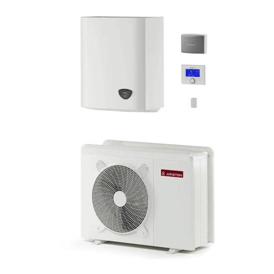
DESCRIZIONE DEL SISTEMA Composizione del sistema Il sistema NIMBUS PLUS S è composto da: - Un’unità interna - Un’unità esterna - Un dispositivo di controllo remoto - Una sonda di temperatura esterna Per ulteriori informazioni sugli accessori disponibili, si prega di consultare il Catalogo Prodotti. - Page 8 70 S - 70 S-T EXT 1016 ø 10 9 0 110 S-T EXT 1016 ø 10 8 / IT...
-
Page 9: Riscaldamento/Raffrescamento
UNITÀ INTERNA Vista complessiva Dimensioni e Pesi 1. Circolatore 2. Manometro 3. Valvola di scarico 4. Sonda di temperatura ritorno dall’impianto di riscaldamento/raffrescamento 5. Pressostato 6. Sonda temperatura TR (tubo refrigerante) 7. Valvola di sicurezza 3 bar 8. Assieme condensatore 9. -
Page 10: Pressione Disponibile
Limiti di funzionamento in raffrescamento Limiti di funzionamento in riscaldamento (-10 ; 60) (35 ; 60) (43 ; 22) (10 ; 22) (-20 ; 45) (35 ; 33) (-20 ; 20) (15 ; 20) (10 ; 5) (43 ; 5) A - Temperatura acqua in uscita (°C) esempio 1: B = 35 e A = 33 B - Temperatura esterna dell’aria (°C) -
Page 11: Dispositivo Di Controllo Remoto
Aggiungendo una Sonda Esterna Ariston: Classe del controllo di temperatura Contributo all'effi cienza energetica % per il riscaldamento degli ambienti In un sistema a 3 zone con 2 Sensori ambiente Ariston: Classe del controllo di temperatura VIII Contributo all'effi cienza energetica % per il riscaldamento degli ambienti... -
Page 12: Guida All'installazione
GUIDA ALL’INSTALLAZIONE Scelta del posizionamento • Evitare il posizionamento dell’unità esterna in luoghi di diffi cile ac- cesso per le successive operazioni di installazione e manutenzione. • Evitare il posizionamento in prossimità di fonti di calore. Attenzione • Evitare il posizionamento in luoghi ove si sottopone l’unità esterna L’installazione delle unità... -
Page 13: Procedura Di Apertura Dei Passaggi Per I Collegamenti
I fori pretagliati per il passaggio dei tubi sono 4: Attenzione 1 sul lato sinistro (C) Prima dell’installazione verifi care la resistenza e l’orizzontalità 1 sul lato posteriore (D) della base di appoggio. Basandosi sulle immagini sotto riportate, 2 sui pannelli di base (E) fi... -
Page 14: Unità Interna
UNITÀ INTERNA 2. Scarico valvola di sicurezza valvola di sicurezza Installazione preliminare 3 bar L’unità interna deve essere posizionata presso un vano con funzione abitativa al fi ne di garantire le migliori prestazioni. Per il posizionamento del sistema utilizzate la dima fornita e una livella. Distanze minime per l’installazione Al fi... -
Page 15: Collegamenti Idraulici E Refrigerante
5) Procedere con la creazione del vuoto fi no a quando il manometro COLLEGAMENTI IDRAULICI indica -101 kPa (dopo circa 15 minuti). 6) Chiudere completamente il rubinetto LOW. CONNESSIONE GAS REFRIGERANTE TRA UNITÁ 7) Spegnere la pompa del vuoto. 8) Verifi care che l’ago del manometro non si sposti per circa 5 minuti INTERNA ED ESTERNA 9) Scollegare la pompa del vuoto. -
Page 16: Recupero Del Refrigerante
Recupero del refrigerante Se si rende necessario scollegare le connessioni per motivi di ripa- razione del circuito gas refrigerante, al fi ne di evitare la perdita dello stesso, occorre eseguire la procedura per riportare tutto il refrigerante nell’unità esterna: 1. svitare i tappi dei rubinetti della valvola a 3 vie. 2. -
Page 17: Installazione Finale Dell'intero Sistema
UNITÀ INTERNA UNITÀ ESTERNA B C D E Scarico valvola di sicurezza 3 bar 3/8” 5/8” Ritorno Sanitario Mandata Sanitario Ritorno Zona 1 Mandata Zona 1 INSTALLAZIONE FINALE DELL’INTERO SISTEMA Legenda: 1. Unità Interna 2. Unità esterna 3. Sonda esterna 4. -
Page 18: Collegamenti Elettrici
COLLEGAMENTI ELETTRICI Attenzione I collegamenti elettrici vanno effettuati dopo aver completato tutti i collegamenti idraulici. L’ unità interna e l’unità esterna devono essere alimentate separatamente seguendo quanto indicato sulle tabelle della norma NF C 15-100. Tra l’unità interna ed esterna dovrà inoltre essere effettuata una connessione di tipo MOD BUS. Questa connessione potrà essere effettuata mediante l’utilizzo di un cavo di sezione ridotta (sezione consigliata 0.75 mm ). -
Page 19: Connessioni Elettriche Dell'unità Esterna
ATTENZIONE: Eseguire il collegamento a terra prima di tutti gli altri collegamenti elettrici. Le unità interne ed esterne devono essere alimentate separatamente. Per evitare qualsiasi rischio, il cavo di alimentazione dell’unità esterna ed interna deve essere sostituito solo da tecnici specializzati . Connessioni elettriche dell’unità... -
Page 20: Connessioni Elettriche Dell'unità Interna
Connessioni elettriche dell’unità interna Prima di ogni intervento sul sistema, interrompere l’alimentazione dall’interruttore generale. Rispettare le connessioni di neutro e fase. Per accedere al quadro elettrico dell’unità interna, rimuovere le tre viti indicate in fi gura (A) ed estrarre il coperchio del quadro elettrico (B). All’apertura del quadro si troveranno le seguenti connessioni: MOD BUS-Comunicazione con l’unità... -
Page 21: Connessioni Elettriche Tra Unità Interna Ed Unità Esterna
Connessioni elettriche tra unità interna ed unità esterna Prima di ogni intervento sul sistema, interrompere l’alimentazione dall’interruttore generale. Il collegamento elettrico tra unità interna ed esterna deve essere eseguito utilizzando le due morsettiere di bassa tensione: GND, A, B. Collegare «GND» sulla morsettiera dell’unità interna con «GND» sulla morsettiera dell’unità esterna. Collegare «A+»... -
Page 22: Schema Elettrico - Quadro Unità Esterna
SCHEMA ELETTRICO - QUADRO UNITÀ ESTERNA 1 ph 3 ph 22 / IT... -
Page 23: Schema Elettrico - Quadro Unità Interna
SCHEMA ELETTRICO - QUADRO UNITÀ INTERNA (WH 90 110 S) BK = Nero YE = Giallo BN = Marrone GN = Verde BU = Blu GY = Grigio RD = Rosso WH = Bianco FLOW METER OR = Arancio PI = Rosa ELECTRICAL RESISTANCE 230V... - Page 24 SCHEMA ELETTRICO - QUADRO UNITÀ INTERNA (WH 70 S) BK = Nero YE = Giallo BN = Marrone GN = Verde BU = Blu GY = Grigio RD = Rosso WH = Bianco FLOW METER OR = Arancio PI = Rosa ELECTRICAL RESISTANCE 230V...
- Page 25 SCHEMA ELETTRICO - QUADRO UNITÀ INTERNA (WH 40 50 S) BK = Nero YE = Giallo BN = Marrone GN = Verde BU = Blu GY = Grigio RD = Rosso WH = Bianco FLOW METER OR = Arancio PI = Rosa ELECTRICAL RESISTANCE 230V...
-
Page 26: Installazione Dell'interfaccia Di Sistema
INSTALLAZIONE DELL’INTERFACCIA DI SISTEMA Posizionamento L’interfaccia di sistema riconosce la temperatura ambiente, per cui si deve tener conto di questo fattore nello scegliere il posizionamento della stessa. Si consiglia un posizionamento lontano da fonti di calore (radiatori, esposizione diretta alla luce solare, camini etc.) così come si consiglia di evitare un posizionamento in prossimità... - Page 27 Interfaccia di sistema simboli display: Tasti e display: 1. tasto indietro (visualizzazione precedente) Estate / Impostazioni acqua calda 2. manopola ) Inverno 3. tasto OK (conferma l’operazione o accede al menu principale) Solo riscaldamento / Impostazioni riscaldamento 4. DISPLAY Raffrescamento OFF sistema spento Programmazione oraria Funzionamento manuale...
-
Page 28: Procedura Di Accensione
17.0.4 BOOST acqua sanitaria ATTENZIONE Premere il tasto OK. Ruotare la manopola e selezionare: Per garantire la sicurezza e il corretto funzionamento dell’inter- - ON (abilita il ciclo per ridurre il tempo di preparazione dell’acqua sanitaria, faccia di sistema, la messa in funzione deve essere eseguita da per un massimo di 180 minuti) un tecnico qualifi... - Page 29 (vedere parameteri 4.2.1/5.2.1/6.2.1). Defi nisce il ritardo con cui viene in- 17.6 Modo manuale - 1 crementata di 4°C la temperatura di setpoint di mandata (fi no ad un massimo Attivazione manuale dei componenti di sistema (circolatori, valvole di 12°C). Se il valore è 0 la funzione non è attiva. deviatrici, resistenze, etc).
- Page 30 Ruotare la manopola e selezionare: - 4. Pronto posa + Funzionale 17.9 Statistiche (riscaldamento del massetto a temperatura variabile da 25°C a 55°C se- 17.10 Diagnostica Pompa Calore - 1 condo il periodo indicato nel grafi co, per un periodo di 18 giorni, riscalda- 17.11 Diagnostica Pompa Calore - 2 mento a temperatura fi...
-
Page 31: Termoregolazione
2. la temperatura ambiente aumenta questo indica che bisogna impo- Termoregolazione Per impostare i parametri di termoregolazione premere contempo- stare una curva con minore pendenza 3. la temperatura ambiente rimane costante, questo indica che la cur- raneamente i tasti indietro “ “... - Page 32 Termoregolazione raffrescamento La verifi ca dell’idoneità della curva scelta richiede un tempo lungo nel Per impostare i parametri di raffrescamento premere contemporane- quale potrebbero essere necessari alcuni aggiustamenti. amente i tasti indietro “ “ e “OK” fi no alla visualizzazione sul display All’aumentare della temperatura esterna (estate) si possono verifi...
-
Page 33: Tabella Menu
IMPOSTAZIONE DESCRIZIONE RANGE DI FABBRICA RETE Rete BUS Interfaccia di sistema Energy Manager Rete BUS attuale Pompa di calore Sensore ambiente Controllo multi zona Interfaccia di sistema Nessuna zona selezionata Numero zona Zona selezionata Correzione temperatura ambiente - 3; +3 Versione SW interfaccia PARAMETRI ZONA 1 Impostazione Temperature... - Page 34 IMPOSTAZIONE DESCRIZIONE RANGE DI FABBRICA Ventilconvettore (FC) Range T Z1 Raffrescamento Pavimento (UFH) Termostati ON/OFF Selezione Tipologia Termoregolaz T Fissa di Mandata ON/OFF Solo Sonda Esterna Curva Termoregolazione [18;33] FC; [0-30] Pavimento 25 FC; 10 Pavimento Spost Parallelo [-2,5°C; +2,5°C] 0°C MinT -12°C [FC];...
- Page 35 IMPOSTAZIONE DESCRIZIONE RANGE DI FABBRICA Velocità fi ssa pompa 20 ÷ 100% 100% Raffrescamento T Set Z2 Raffrescamento par. 5.5.6 - 5.5.7 7°C [FC] - 18°C [UFH] Ventilconvettore (FC) Range T Z2 Raffrescamento Pavimento Pavimento (UFH) Termostati ON/OFF TSelezione Tipologia Termoregolaz T Fissa di Mandata ON/OFF Solo Sonda Esterna...
- Page 36 IMPOSTAZIONE DESCRIZIONE RANGE DI FABBRICA Attivazione modo silenzioso OFF - ON Ora attivazione modo silenzioso 00 : 00 ÷ 24:00 22:00 Ora disattivazione modo silenzioso 00 : 00 ÷ 24:00 06:00 BOOST acqua sanitaria OFF - ON PV Delta T DHW Setpoint Temp. 0 - 20°C Confi...
- Page 37 IMPOSTAZIONE DESCRIZIONE RANGE DI FABBRICA Bassa velocità Funzionamento Circolatore Alta velocità Modulante Modulante DeltaT obbiettivo x modulaz 5 ÷ 20°C 5°C Max PWM pompa min PWM ÷ 100% 100% Min PWM pompa ÷ max PWM 100% Temp mand per Asciug Massetto 25 ÷...
- Page 38 IMPOSTAZIONE DESCRIZIONE RANGE DI FABBRICA Uscita segnale ausiliare TDM OFF - ON Cicli di verifi ca Ciclo Disareazione OFF - ON Funzionale Pronto posa Ciclo asciugatura del massetto Funzionale + Pronto posa Pronto posa + Funzionale Manuale Tot gg restanti asciugatura massetto solo lettura gg restanti asciugatura funzionale solo lettura...
- Page 39 IMPOSTAZIONE DESCRIZIONE RANGE DI FABBRICA Stand by Raffrescamento Riscaldamento Modalità Booster riscaldamento Modalità Booster raffrescamento Modalità Rating riscaldamento Modalità Operative Pompa di Calore Modalità Rating raffrescamento sola lettura Protezione Antigelo Sbrinamento Protezione sovratemperatura Timeguard Errore sistema Errore sistema (reset di servizio) Recupero refrigerante Errore Pompa 0 ÷...
- Page 40 IMPOSTAZIONE DESCRIZIONE RANGE DI FABBRICA stand-by antigelo riscaldamento sanitario funzione sanifi cazione termica funzione disareazione funzione chimney Ciclo asciugatura del massetto no generazione calore Stato sistema sola lettura modo manuale errore inizializzazione raffrescamento Antigelo Sanitario Integrazione fotovoltaico Deumidifi cazione recupero refrigerante Temp Impostata Risc sola lettura Temp mandata riscaldamento...
-
Page 41: Manutenzione
MANUTENZIONE Funzione antigelo Protezione antigelo dell’unità esterna. Il circolatore primario dell’unità interna parte alla minima velocità La manutenzione è un’operazione essenziale per la sicurezza, il corret- quando la temperatura misurata dalla sonda ad immersione (LWT) è to funzionamento e la durata di vita del sistema. inferiore a 10°C in modalità... -
Page 42: Lista Errori Unità Interna
LISTA ERRORI UNITÀ INTERNA ERRORE DESCRIZIONE RISOLUZIONE - Attivazione della termoregolazione basata sulla sonda esterna. Sonda Esterna Difettosa - Sonda esterna non connessa o danneggiata. Sovraccarico alimentazione bus Sonda Mandata Z1 Difettosa Sonda Mandata Z2 Difettosa Sonda Mandata Z3 Difettosa Sonda Ritorno Z1 Difettosa Sonda Ritorno Z2 Difettosa Sonda Ritorno Z3 Difettosa... -
Page 43: Lista Errori Unità Esterna
Errore pre-circolazione Flusso non rilevato per 5 minuti durante la pre-circolazione Confi gurazione d’ingresso SG ready non completato Solo uno dei parametri 17.1.0 o 17.1.1 è impostato come input SG Ready (*) Sovraccarico alimentazione BUS E’ possibile il verifi carsi di un errore di sovraccarico alimentazione BUS, dovuto alla connessione di tre o più... -
Page 44: Targhette Caratteristiche
Targa Dati dell’Unità Interna Targa Dati dell’Unità Esterna Legenda: 1 Marchio Legenda: 2 Modello 3 Dati riscaldamento 1. Marchio 4 Prestazione nominale riscaldamento 2. Produttore 5 Dati raffrescamento 3. Modello - Nr. di serie 6 Prestazione nominale raffrescamento 4. Codice commerciale 7 Tipo olio del circuito frigorifero 5. - Page 45 INDEX Overview Setting Safety regulations ..................... 38 Setting of parameters ..................58 Characteristics of the water supplied to the appliance ...... 41 Thermoregulation ..................... 60 Menu table ......................62 System description System compositions ..................49 Maintenance Weights and dimensions ................42 General remarks ....................
- Page 46 SAFETY REGULATIONS grafo. Fire caused by overheating due to electrical cur- CAUTION rent passing through undersized cables. This manual constitutes an integral and essential part of the product. It must be kept Protect all connection pipes and wires in order with care and accompany the product at all to prevent them from being damaged.
- Page 47 Make sure any rolling ladders are positioned securely, that they are suitably strong, that the Reset all the safety and control functions af- steps are intact and not slippery and that the fected by any work performed on the applian- ladders are fi...
- Page 48 WARNING: Cleaning the heating system At the fi rst installation, it is necessary to pre-clean the installa- tion. All operation concerning installation, maintenance, and In order to ensure the proper functioning of the appliance, other malfunction shall be done by qualifi ed staff . after each cleaning operation or water substitution, verify that Do not leave fl ammable material in the vicinity of the system.
- Page 49 SYSTEM DESCRIPTION System composition NIMBUS PLUS system consists of: - External unit - Internal unit - System interface - Outdoor sensor For more information on available accessories, please refer to the product catalogue. EXTERNAL UNIT As external unit, one of the following models is provided: •...
- Page 50 70 S - 70 S-T EXT 1016 ø 10 90-110 S-T EXT 1016 ø 10 50 / GB...
- Page 51 INTERNAL UNIT Overall view Weights and dimensions (mm) 1. Circulator 2. Manometer 3. Discharge valves 4. Temperature sensor (return from the installation) heating/cooling 5. Pressure switch 6. TR Sensor (Temperature Refrigerant) 7. Safety valve 3 bar 8. Condenser assembly Expansion vessel LWT Sensor (Leaving Water Temperature) 1.
- Page 52 Restrictions of cooling operation Restrictions of heating operation (-10 ; 60) (35 ; 60) (43 ; 22) (10 ; 22) (-20 ; 45) (35 ; 33) (-20 ; 20) (15 ; 20) (10 ; 5) (43 ; 5) A - Flow water temperature (°C) Example: 1B = 35 and A = 33 B - External air temperature (°C) AVAILABLE PRESSURE...
- Page 53 Adding an ARISTON OUTDOOR SENSOR: Class of the temperature control Contribution to seasonal space heating energy effi ciency in % In a 3-zones system with 2 ARISTON ROOM SENSORS Class of the temperature control VIII Contribution to seasonal space heating energy effi ciency in %...
- Page 54 • Do not place the external unit on structures that do not gua- INSTALLATION GUIDE rantee support. • Avoid placing it in close proximity to fuel tanks of gas. Warning • Avoid a positioning that provides exposure to oil vapors. The appliance must be installed by a qualifi ed technician •...
- Page 55 The precutted holes for the passage of pipes are 4: Attention 1 on the right side (C) Before installation, check strength and horizontality of 1 on the back side (D) the base. Based on the pictures, connect the base of the 2 on the base panels (E) external unit fi rmly to the ground, using suitable anchor bolts (M10 x 2 pairs).
- Page 56 2. Safety valve drain INTERNAL UNIT safety valve Preinstallation 3 bar The indoor unit should be positioned in a compartment at home, in order to ensure the best performance. Use the template provi- ded and a spirit level for positioning the system. Minimum clearance In order to allow the proper maintenance of the appliance, you must observe the minimum clearances for installation as shown in...
- Page 57 5) Proceed with evacuation until the compound pressure gauge GAS CONNECTIONS BETWEEN INTERNAL UNIT indicates -101 kPA (after about 15 minutes). AND EXTERNAL UNIT 6) Close LO handle completely. 7) Turn off the vacuum pump. 8) Keep this status for 2 minutes while checking that compound ATTENTION gauge’s pointer does not return.
- Page 58 Refrigerant recover If it becomes necessary to disconnect the refrigerant connec- tions for unit repair, removal or disposal, in order to avoid re- frigerant loss to the atmosphere, the pump down operation must be carried out. Pump-down is an operation intended to collect all the system refrigerant in the outdoor unit: 1.
- Page 59 INTERNAL UNIT EXTERNAL UNIT B C D E Discharge of safety valve 3 bar 3/8” 5/8” DHW Return DHW Flow Return Zone 1 Flow Zone 1 FINAL INSTALLATION OF THE WHOLE SYSTEM Legend: 1. Internal unit 2. External unit 3. External sensor 4.
- Page 60 ELECTRICAL WIRING ATTENTION The electrical connections shall be made after completing all hydraulic connections. The internal and external units must be powered separately according to what is indicated on the tables. Between the internal and external units should also be made a MOD BUS connection. This connection may be made through the use of a cable of reduced section (recommended section 0,75 mm ).
- Page 61 WARNING: Make ground connection prior to any other electrical connections. The internal and external units must be powered separately. To prevent any risk, the power supply cable of the outdoor and indoor unit must only be replaced by the technicians of the after-sales service.
- Page 62 Internal Unit electrical connection efore any operation on the system, turn off the main power. Observe the phase and neutral connections. To access the control panel of the internal unit, proceed as follows: Remove the three screws (A) indicated in fi gure and remove the cover of the electrical panel (B).
- Page 63 Electrical connections between internal and external unit Before any work on the system, shut off the power at the breaker. Electrical connections between internal and external units must be performed using the three low voltage terminals: GND, A, B. Connect «GND» on the terminal block of the internal unit with «GND» on the external terminal block. Connect «A+»...
- Page 64 ELECTRICAL SCHEME - BOX OF EXTERNAL UNIT 1 ph 3 ph 64 / GB...
- Page 65 ELECTRICAL SCHEME - BOX OF INTERNAL UNIT (WH 90 110 S) BK = Black YE = Yellow BN = Brown GN = Green BU = Blue GY = Grey RD = Red WH = White FLOW METER OR - Orange PI - Pink ELECTRICAL RESISTANCE...
- Page 66 ELECTRICAL SCHEME - BOX OF INTERNAL UNIT (WH 70 S) BK = Black YE = Yellow BN = Brown GN = Green BU = Blue GY = Grey RD = Red WH = White OR - Orange PI - Pink FLOW METER ELECTRICAL RESISTANCE...
- Page 67 ELECTRICAL SCHEME - BOX OF INTERNAL UNIT (WH 40 50 S) BK = Black YE = Yellow BN = Brown GN = Green BU = Blue GY = Grey RD = Red WH = White OR - Orange PI - Pink FLOW METER ELECTRICAL RESISTANCE...
- Page 68 INSTALLATION OF SYSTEM INTERFACE Positioning The system interface recognizes the temperature of the environment, so this factor must be taken in consideration during the choice of the positioning of the same. We recommend to place the remote control away from sources of heat (radiators, direct exposure to sunlight, fi...
- Page 69 Display symbols: Buttons and Display: 1. back button (previous screen) Summer / DHW settings ) Winter 2. knob button Only Winter / CH settings (to confi rm operation or access main menu) Cooling 4. DISPLAY OFF, system off ) Time program ) Manual operation Desired room temperature Room temperature detected...
- Page 70 - 0. Green WARNING (excludes the electric resistances for the integration of the he- To guarantee safety and correct operation of the system inter- ating) face, it must be commissioned by a qualifi ed technician in pos- - 1.Standard session of the skills as required by law. Press the OK button to confi rm.
- Page 71 17.1.4 AUX Output 1 (AFR) Push OK button. - 0. None Turn the knob and select: - 1. Fault alarm: the contact is closed in case of fault 17.4 Cooling - 2. Humidistat alarm: the output is closed when the AUX 1 is Press the OK button.
- Page 72 17.7.2 Force Hp Cool - 4. Curing Heating + Functional Heating Activate the heat pump in cooling mode (fl oor drying done with variable temperature from 25°C to 17.7.3 Rating Heating Mode 55°C for the fi rst 18 days and then at fi xed temperature of 17.7.4 Rating Cooling Mode 55°C for the following 6 days) 17.7.5 Fixed compressor frequency...
- Page 73 Thermoregulation arise: To set the temperature adjustment parameters, simultaneously 1. The temperature of the room may fall, indicating that a steeper press and hold the back “ “ and “OK” buttons until “Enter code” curve should be set; appears on display. Turn the knob to enter the technical code 2.
- Page 74 To set the temperature adjustment parameters, simultaneously When the outdoor temperature rises (summer), three condi- press and hold back “ “ and “OK” buttons until “Enter code” tions may arise: appears on the display. Turn the knob to enter the technical 1.
- Page 75 DESCRIPTION RANGE DEFAULT NETWORK BUS network System interface Energy Manager Network presence Heat Pump Room Sensor Zone Manager System interface No zone selected Zone number Zone selected Room temperature correction - 3; +3 SW Version Interface ZONE1 PARAMETERS Setpoint T Day 10 - 30 °C 19°C Heat - 24°C Cool T Night...
- Page 76 DESCRIPTION RANGE DEFAULT Zone2 Parameters (if present) Setpoint T Day 10 - 30 °C 19°C Heat - 24°C Cool T Night 10 - 30 °C 16°C T set Z2 par. 5.2.5 - 5.2.6 20 (LT) - 40 (HT) Zone frost temperature 2 - 15 °C 5°C Free parameters...
- Page 77 DESCRIPTION RANGE DEFAULT Target deltaT for pump modulation cooling [-5; -20°C] -5°C ZONE MODULE (if present) Manual Mode ZM Manual mode activation OFF - ON Z1 Pump control OFF - ON Z2 Pump control OFF - ON Z2 Mix Valve Control Open Close General Zone Module...
- Page 78 DESCRIPTION RANGE DEFAULT None AUX Input 1 None Humidistat sensor None Fault alarm AUX Output 1 (AFR) None Humidistat alarm External heat request. None Fault alarm AUX Output 2 None Humidistat alarm External heat request Energy manager parameter 1 None Plus Hydraulic scheme Compact...
- Page 79 DESCRIPTION RANGE DEFAULT Disabled Time based Always Active Comfort Function Green Mode HC-HP HC-HP 40°C Green Mode Max HP charging time 30 ÷ 240 min. 120 min. Antilegionella Function ON - OFF Antilegionella start time [hh:mm] [00:00-24:00] 01:00 Manual Mode - 1 Manual mode activation OFF - ON HP circulator control...
- Page 80 DESCRIPTION RANGE DEFAULT Resistor Stage 2 running hours (h/10) only read Resistor Stage 3 running hours (h/10) only read Resistor Stage 1 On cycles (n/10) only read HP Defrost hours (h/10) only read Cooling running hours (h/10) only read Heating running hours (h/10) only read DHW running hours (h/10) only read...
- Page 81 DESCRIPTION RANGE DEFAULT 4way valve heat/cool only read Base Panel Heater Status only read Compressor phase current only read (mA) EM Diagnostics - 1 Input Stand-by Antifreeze Cycle Heating Cycle DHW Cycle Thermal Cleanse Function Air Purge Function Chimney Function Floor drying cycle No Heat Generation Energy Manager Status...
- Page 82 MAINTENANCE Antifreeze function The system has a frost protection. Maintenance is an essential operation to insure safety, correct working and duration of life of the appliance. Frost protection of the external unit : the primary circulator of the It must be carried out in accordance with the regulations in force. internal unit is switched on if the return water temperature to the It is requested to check periodically the pressure of the refrigerant external unit is equal to or less than 7 °...
- Page 83 INTERNAL UNIT ERROR LIST ERROR DESCRIPTION TROUBLESHOOTING Activation of thermoregulation based on outdoor sensor and outdoor Outdoor Sensor Damaged sensor not connected or damaged Bus supply overload Zone1 Send Probe Damaged Zone2 Send Probe Damaged Zone3 Send Probe Damaged (N/A) Zone1 Return Probe Damaged Zone2 Return Probe Damaged Zone3 Return Probe Damaged (N/A)
- Page 84 (*) BUS power supply overload A BUS power supply overload error may occur due to the con- nection of three or more devices within the installed system. Devices which may overload the BUS network include: microswitch - Multizone module - Solar pump assembly - Module for instant production of domestic hot water (**) Table of inverter error codes To avoid overloading the BUS power supply, set microswitch...
- Page 85 Internal unit data plate External unit data plate Legend: Legend: 1. Homologation Brand 2. Certifi cation Manufacturer 3. Model Appliance model - Serial number 4 Performance Ratings heating circuit Commercial reference 5 Cooling date Certifi cation number 6 Performance Ratings cooling circuit Electrical data 7 Type of oil in the refrigerant circuit 11.
- Page 86 86 / IT...
- Page 87 87 / IT...
- Page 88 Ariston Thermo SpA Viale Aristide Merloni, 45 60044 Fabriano (AN) Italy Telefono 0732 6011 Fax 0732 602331 info.it@aristonthermo.com...
Need help?
Do you have a question about the NIMBUS PLUS 40 S EXT and is the answer not in the manual?
Questions and answers