Table of Contents
Advertisement
Quick Links
Advertisement
Table of Contents

Related Manuals for CAME BPT VAS-101


Summarization of Contents
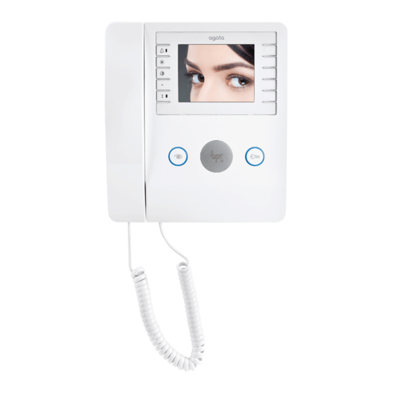
AGATA VC-V Installation and Features
Wall mounting
Instructions for wall mounting the AGATA VC-V unit, including box compatibility and attachment.
Terminal board M1
Details connections for Doorbell and BUS line input on terminal board M1.
AGATA VC-V Technical Specifications
Technical features
Specifications for the AGATA VC-V, including power, absorption, and display details.
AGATA VC-V Programming Procedures
Accessing programming
Procedure to enter programming mode by pressing the key Delta for 3 seconds.
Programming the melody associated to the call from the entry panel
How to select melodies for calls from the entry panel, with 1 acoustic signal.
Programming the melody associated with the doorbell
Steps to program doorbell melodies using 2 acoustic signals.
Programming the number of call rings
Procedure to set the number of call rings (1 to 6) for the entry panel.
VAS/101 Installation and Specifications
Installation
Guidelines for installing the VAS/101 power supply horizontally on a DIN rail.
Terminal board M1
Details of the Mains terminal board connections for the power supply.
Terminal board M2
Connections for 18 VDC power supply and protection against overloads.
Technical features
Specifications for the VAS-101 power supply, including voltage and dimensions.
LVC/01 Installation Procedures
Wall mounting
Instructions for mounting the LVC/01 entry panel on the wall, including fixing and hose routing.
Recessed installation
Steps for installing the LVC/01 entry panel in a recessed box, considering camera position and cable routing.
LVC/01 Components and Settings
Accessories
Overview of available accessories for the LVC/01 entry panel.
Personalized labels: Dimensions
Specifications for the dimensions of personalized user labels.
Terminal function
Explanation of the terminal connections and functions on the VLS/300 unit.
Terminal board M1
Details connections for BOUT (Riser) and power supply 16-18 VDC.
Terminal board M2
Connections for Earth, Door lock release button (NA), and Solenoid lock.
LED functions and adjustments
Explanation of LED indicators for loudspeaker, microphone, and solenoid lock status.
LED symbology
Symbols and meanings for LED states: Off, On, Slow flashing, Quick flashing.
LVC/01 Programming and Configuration
Initial programming
Procedure to enter programming mode using the PROG key and LED indicators.
Programming of the Key Type
How to program the type of entry panel keys.
Programming the call keys
Steps to associate call keys with internal extensions using receiver and buttons.
Exiting programming
How to exit the programming mode by pressing the PROG key.
Entering Programming Mode
Method to enter programming mode using the PROG key and LED feedback.
Programming the call keys
Associating call keys with internal extensions via receiver and specific buttons.
Exiting programming
Procedure to exit programming mode by briefly pressing the PROG key.
Programming key type
How to program the type of entry panel keys within a specific stage.
Product Disposal Guidelines
DISPOSAL
Guidelines for environmentally sound disposal of packing material and equipment.
Need help?
Do you have a question about the VAS-101 and is the answer not in the manual?
Questions and answers